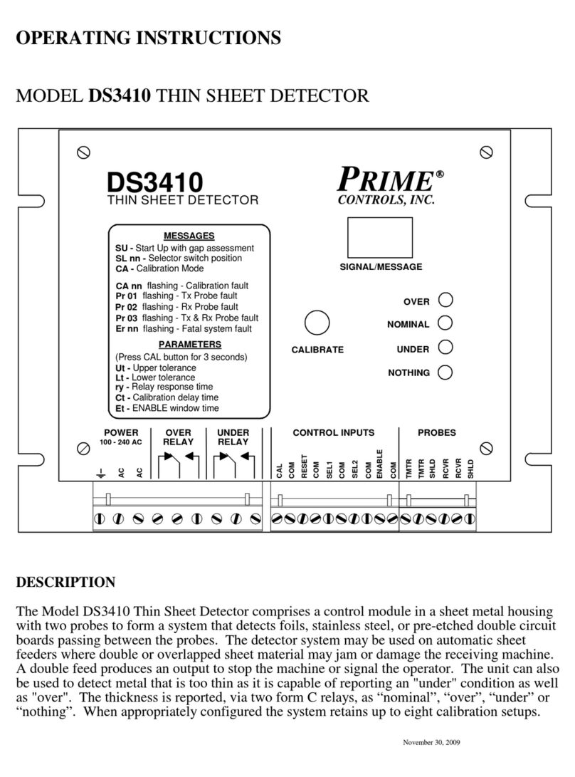
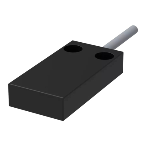
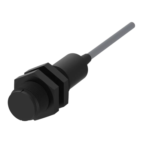
elobau eloProtect M 165MSK Series Quick guide

Art.-Nr./Art. No./Réf./N° art/N° art.: 9010002B01M Version: 1.1 Date: 11.04.2016 1/11
165MSK...
Safety sensor series 165MSK...
Translation of the original operating instructions
Table of contents
1 About these operating instructions .................................................... 1
2 Designated use.................................................................................. 1
3Approvals........................................................................................... 1
4 Safety instructions ............................................................................. 2
5 Warning against misuse .................................................................... 2
6 Exclusion of liability ........................................................................... 2
7Function............................................................................................. 2
8 Technical specifications..................................................................... 2
9Installation ......................................................................................... 2
10 Adjustment......................................................................................... 3
11 Electrical connection.......................................................................... 3
12 Commissioning .................................................................................. 3
13 Maintenance ...................................................................................... 3
14 Dismantling........................................................................................ 3
15 Disposal............................................................................................. 3
16 Information on the manufacturing date.............................................. 6
Declaration of conformity ........................................................................... 20
1 About these operating instructions
The following standard models are described:
165MSK00.1.
Data sheets can also be requested from elobau for customer-specific safety
sensors. The information specified in the data sheet applies for customer-
specific models if this information deviates from the operating instructions.
The person installing the safety sensor is to be provided with the operating
instructions.
The operating instructions must be kept in a legible condition and in an
accessible location.
Meaning of the symbols used:
Warning
Failure to observe this warning may result in faults or malfunc-
tions.
Failure to observe this warning may result in personal injury
and/or damage to the machine.
Information
Indicates available accessories and useful additional informa-
tion.
GB 165MSK...
Type key safety sensor
Type key actuator
165MSK00.1.
A = N.O. contact / N.O. contact
B = N.O. contact / N.O. contact / LED
C = N.O. contact / N.O. contact / control contact N.O. contact
D = N.O. contact / N.O. contact / control contact N.O. contact /
LED
E = N.O. contact / N.O. contact / lateral control
F = N.O. contact / N.O. contact / lateral control / LED
G = N.O. contact / N.C. contact
H = N.O. contact / N.C. contact / LED
I = N.O. contact / N.C. contact / control contact N.O. contact
J = N.O. contact / N.C. contact / control contact N.O. contact /
LED
K = N.O. contact / N.C. contact / lateral control
L = N.O. contact / N.C. contact / LED / lateral control
H = Plug M12x1 4-pole Pigtail
J = Plug M12x1 8-pole Pigtail
K = Cable
165MBK.01
0 = standard (non-reinforced); end face
1 = reinforced, end face
2 = standard (non-reinforced); 90°
3 = reinforced, 90°
4 = special design
2 Designated use
In combination with the elobau safety control units or similar safety controllers,
the safety sensors and actuator 165MBK... are exclusively used to monitor
moving, isolating safety devices.
The safety control units (or similar) detailed in chapter 7 “Function” on page 4
achieve PDF-M / PDF-S-classification according to EN 60947-5-3 in combin-
ation with the safety sensors and actuators.
The overall control concept in which the safety sensor is incorporated, must be
validated, for example, according to EN ISO 13849-2.
3 Approvals
[INDUSTRIAL CONTROL SWITCH]
E336137
(Tested according to ECOLAB
standard)
Test media:
- Distilled water
- P3-topax 66
- P3-topactive 200
- P3-topax 52
- P3-topax 990

Art.-Nr./Art. No./Réf./N° art/N° art.: 9010002B01M Version: 1.1 Date: 11.04.2016 2/11
4 Safety instructions
5 Warning against misuse
6 Exclusion of liability
No liability shall be accepted for any damage or operational faults caused by a
failure to observe these operating instructions. All further liability of the
manufacturer is excluded in the case of damage caused by the use of
replacement and accessory parts that have not been authorized by the
manufacturer.
No unauthorized repairs, conversions or modifications are permitted for reasons
of safety and the manufacturer shall not be liable for any damage resulting
therefrom.
7 Function
A coded magnetic safety sensor with a non-contact activation through a coded
actuator.
(Type 4; low coding level according to EN ISO 14119)
An elobau safety control unit or similar safety processing unit / safety controller
analyses the switching state of the safety sensor. PDF-M and PDF-S is
achieved only in combination with the elobau safety control units listed below or
comparable safety control units / safety controllers.
The safety sensors are suitable for the following elobau safety control units:
- Ensure that the safety sensors are only mounted and put into
operation by specially-trained and authorised personnel.
- Only install and put the device into operation once you have
read and understood the operating instructions and are familiar
with the applicable regulations on occupational safety and
accident prevention.
- The safety sensor may only be activated by a correctly mounted
actuator on the safety device. Actuation by a spare actuator that
is not mounted to the safety device is prohibited.
- The safety sensors may only be operated in a perfect function-
ing condition.
- Ensure that the safety sensors are exclusively used to protect
against risks.
- Ensure that all of the valid safety regulations for the respective
machine are complied with.
- Ensure that all of the valid laws and directives are complied with.
- Connecting safety sensors in series can, under certain
circumstances, reduce their performance level according to
EN ISO 13849-1 standards due to a lower detection of errors.
- There are no known residual risks, if all of the information
contained in these operating instructions is complied with.
- In case of incorrect or unintended use or manipulation, the use
of the safety sensors does not exclude risks to persons or
damage to machine or system components.
Please also observe the relevant information stipulated in
EN ISO 14119.
- Please ensure that when using safety control units that have not
been supplied by elobau, no current or voltage peaks which are
higher than the specified electrical data of the safety sensor are
generated by these devices. Current or voltage peaks are
produced, for example, by capacitive or inductive loads.
- The safety sensor is not short-circuit proof.
- An exceeding of the electrical data of the safety sensor (e.g. in
the event of incorrect wiring or short-circuits) may cause
irreparable damage to the sensor.
- The safety sensor may only be activated in the approved control
options (see Technical specifications).
Non-compliance with this information may result in reduced
service life of the safety sensor.
PDF-M according to EN 60947-5-3:1999 + A1:2005
(corresponds to PLe /Cat.4) for:
470... 470EFR3E11K_
470EFR3E12K_
471... 471M41H31
471EFR3E11K_
471EFR3E12K_
471EFR3E13K_
471EFR3E14K_
eloProg 485EPB
485EPE08A02
485EPE08
4854EPE12
485EPE16
PDF-S according to EN 60947-5-3:1999 + A1:2005
(corresponds to PLd /Cat.3) for:
463... 463111B1
463111B2
463114B1
463114B2
463111B101
463114B101
463121B1
463124B1
470... 470111B1
470115B1
470121B1
470125B1
470EFR2D12K_
471... 471EFR2D14K_
8 Technical specifications
See Technical specifications beginning on page page 14.
9 Installation
- Safety sensor and actuator
do not use as end stops
do not install in strong magnetic fields
do not expose to any strong shocks or vibrations
keep away from iron filings
- The safety sensor and the accompanying actuators may only be mounted in
a voltage-free state.
- Ensure that all safety sensor and actuator markings are congruently
opposed to one another.
- The installation position is arbitrary. The safety sensor and actuator must
however be mounted in parallel, facing each other.
- Please note the specified installation tolerances and the approved control
options.
- Since the safety sensor is a non-embeddable proximity switch (in
accordance with EN 60947-5-2), the safety sensor and the actuator should
be mounted on non-ferromagnetic material. A free zone of 25 mm is required
in the event that this cannot be avoided.
- Where possible, the safety sensor and actuator should not be mounted on
ferromagnetic material. Changes to the switching distances are to be
expected. A non-ferromagnetic spacer with a thickness of at least 10 mm
must be used in order to avoid influencing the switching distances. The
above-mentioned free zone still applies to the safety sensor and actuator.
- The mounting distance between two safety sensor and actuator systems
must be at least 50 mm.
- Tightly fasten the safety sensor and actuator to the safety device.
Suitable spacer plates for the
safety
sensor and actuator are
available from elobau under order number 350008.

Art.-Nr./Art. No./Réf./N° art/N° art.: 9010002B01M Version: 1.1 Date: 11.04.2016 3/11
165MSK...
- Only M4 flat head screws (e.g. M4 cylinder head screws ISO 4762) may be
used for mounting the safety sensor and actuator. Max. tightening torque
0.7 Nm. Screws made from non-ferromagnetic material (e.g. brass) must be
used.
- The safety sensor may only be mounted on an even surface as failure to do
so may lead to tension which could damage the safety sensor or alter the
switching distances.
- The connection cable of the safety sensor must be protected against
mechanical damage.
- During the assembly process, the requirements according to EN 14119
should be taken into consideration.
- Consider the requirements of EN 60204-1 when mounting, in particular with
regard to appropriate laying. It is recommended to conceal the safety sensor
lead.
10 Adjustment
- Always test the correct functionality with one of the approved safety control
units.
- The specified switching distances (see Technical specifications from
page 14) only apply for mounting on non-ferromagnetic material if the safety
sensor and actuator are mounted in parallel and facing each other. Other
layouts may lead to deviating switching distances.
11 Electrical connection
- Electrical connection is permitted in voltage-free state only.
- Connect the safety sensor according to the specified wire colours or pin
assignment (see Technical specifications from page 14).
- Please ensure that the voltage does not fall below the required minimum
input voltage of the downstream safety processing unit. For that reason
observe the voltage drop at the safety sensor (series resistor) and in the
connection cable.
- The voltage drop for the internal LED circuit is to be considered additionally
for LED safety sensors (see Technical specifications).
- For series connection of the safety sensors (verify approval in advance) their
respective NO paths must be connected in series and the respective NC
paths must be connected in parallel.
12 Commissioning
When commissioning, the following points must be ensured in advance:
- The safety sensor and actuator are positioned correctly and mounted in a
fixed position.
- The supply line is intact.
- There are no iron filings on the safety sensor and actuator.
The safety sensor and the connected control unit must then be tested for correct
functionality.
13 Maintenance
If the safety sensor is mounted and used correctly, no maintenance measures
are be necessary.
We recommend a visual and functional inspection carried out at regular
intervals:
- Check that the safety sensor and actuator are firmly seated.
To secure the mounting screws against easy disassembly, we
recommend using the screw covers included.
For safety sensors with connection plugs, suitable cable sets and
connectors for assembly are directly available from elobau (see
Technical specifications from page 14
).
The control contact is not a safety contact.
It may not be incorporated into a safety circuit.
Use the control contact for non safety-relevant signal and control
functions only.
If several safety sensors with LED are used, the brightness of the
LEDs can decrease with an increasing number of closed safety
doors.
14 Dismantling
The safety sensor may only be dismantled in a voltage-free state.
15 Disposal
Dispose of packaging and used parts in accordance with the regulations of the
country in which the device is installed.
16 Information on the manufacturing date
The manufacturing date can be seen on the safety sensor casing
in the form of "week/year":
e.g. 37/14 = week 37/ year 2014

165MSK...
Art.-Nr./Art. No./Réf./N° art.: 9010002B01M Version: 1.1 Date: 11.04.2016 4/11
Technical specifications
Electrical data 165MSK00.1.
Switching voltage U1) 24 V DC +/- 20 %
Max. switching current safety
contact
- without LED
- with LED (green colour)
For UL approval: resistive
200 mA (-25°C...+80°C)
10 mA (-25°C...+70°C)
5 mA (>70°C...+80°C)
Max. switching current control
contact 50 mA
Series resistor safety contact
- without LED
- with LED (green colour)
For UL approval: resistive
10 Ω(0,75 W)
10 Ω(0,10 W)
Series resistor control contact 10 Ω(0,25 W)
Max. voltage drop additionally
for LED Ud3,7 V
Max. frequency of operating
cycles 5 Hz
Max. rated insulation voltage Ui300 V DC / 250 V AC
Rated impulse withstand voltage
Uimp 0,8 kV
Degree of pollution 3
Usage category DC 12
Type key actuator 165MSK00.1.
Standard actuator 165MBK001 / 165MBK201
Amplified actuator for larger
operating distances 165MBK101 / 165MBK301
Secured operating distance Sao
Standard
Reinforced
5 mm
8 mm
Safe distance for switching off Sar
Standard
Reinforced
14 mm
18 mm
Repeat accuracy [R]
Differential travel [H] / standard /
reinforced
< 0,2 mm
3,5 mm
Minimum air gap Somin 0,5 mm

165MSK...
Art.-Nr./Art. No./Réf./N° art.: 9010002B01M Version: 1.1 Date: 11.04.2016 5/11
Environmental data 165MSK00.1.
Ambient temperature
(connection cable in a fixed
position)
For UL approval:
- 25 °C ... +80 °C
- 25 °C ... +55 °C
- 25 °C ... +65 °C
- 25 °C ... +40 °C
1
- 25 °C ... +80 °C
30 g / 11 ms
10 Hz ... 55 Hz
1 mm
IP67
IP6K9K
Mechanical specifications 165MSK00.1.
Mounting position arbitrary —
Non-flush mountable —
Housing material
PBT colour: grey
PC colour: black
✓
✓
Max. torque for fastening screw 0,7 Nm
Dimensions 88 mm x 25 mm x 13 mm
Weight approx.
- Safety sensor with 1m/3m /5m/
10m connection piping
- Safety sensor with plug
- Actuator
145 g / 345 g / 545 g / 1045 g
45 g
35 g
-
-
-
without LED
with LED (green colour)
plug version
(without/with LED)
Area type class
Storage and transport
temperature
Shock resistance EN 60947-5-2
Vibration resistance according
to EN 60947-5-2
Amplitude
Protection class in accordance
with EN 60529
Degree of protection according to
ISO 20653:2013
(excluding plugs)2)

165MSK...
Art.-Nr./Art. No./Réf./N° art.: 9010002B01M Version: 1.1 Date: 11.04.2016 6/11
Connection types 165MSK00.1.
Connection cable grey PVC LiYY 4x0,25mm² / 6x0,25mm²
(AWG 24)
Connector with Pigtail
(according to
EN 61076-2-101:2012)
- M12x1, 4-pole, black/grey
- M12x1, 8-pole, black/grey
PVC LiYY M12x1 4x0,25mm² (AWG 24)
PVC LiYY M12x1 8x0,25mm² (AWG 24)
Mating plug available for
- M12x1, 4-pole, black/grey
- M12x1, 8-pole, black/grey
(elobau article number)
K14G00.K
K18G00.K
Cable diameter (± tolerance)
4-core / 4-pole
6-core / 8-pole
Ø 4,7 mm ± 0,25 mm
Ø 6,0 mm ± 0,30 mm
Max. torque for plug 0,6 Nm
Max. cable length 30 m
1) The safety sensor must be
supplied directly or indirectly to a
SELV / PELV power supply unit.
2) Only for use in industrial
equipment in accordance with
NFPA 79
Safety parameters 165MSK00.1.
B10d according to
EN ISO 13849-1:2008
Appendix C
(at max. 20% contact load)
20.000.000
Service life in years 20
An individual safety sensor can
be used up to 1)
Kat.4 / PL e (EN ISO 13849-1)
SILCL 3 (IEC/EN 62061)
SIL 3 (IEC/EN 61508)
2
1
7
6
5
43
2
8
3
1
4

165MSK...
Art.-Nr./Art. No./Réf./N° art.: 9010002B01M Version: 1.1 Date: 11.04.2016 7/11
Specifications in accordance
with EN 61508
165MSK00.1.
Classification in accordance with
EN 60947-5-3:1999+A1:2005
2)
PDF-M PDF-S
Diagnostic Coverage (DC)
min. high (PDF-M)
min. medium (PDF-S) ✓
✓
Min. Safe Failure Fraction
(SFF) 99,5% 95%
Min. category/PL in accordance
with EN ISO 13849-1:2008 4/PL e 3/PL d
SIL in accordance with
(IEC/EN 62061)
SIL in accordance with
(IEC/EN 61508)
SILCL 3
SIL 3
MTTFd (years) 2707
PFHd(1/h) 8,43 x 10⁻⁹ 8,44 x 10⁻⁹
1)
- For this, at least the following
measures are required:
- Short circuit recognition
through differing voltages
or pulsed signals
- Two-channel structure
(see EN ISO 13849-1:2008)
2)
- The usable safety control units
can be found in chapter 7,
"Function" of this manual

165MSK...
Art.-Nr./Art. No./Réf./N° art.: 9010002B01M Version: 1.1 Date: 11.04.2016 8/11
1 6 5 M S K 0 0 . 1 . 1 6 5 M S K 0 0 . 1 .
165MBK001 / 165MBK101 165MBK001 / 165MBK101
AA
165MBK201 / 165MBK301 165MBK201 / 165MBK301
Somin
Sao
Sar
A
B
C
D
G
H
I
J
H
J
K
E
F
K
L
H
J
K
Somin
Sao
Sar
Somin
Sao
Sar
Somin
Sao
Sar
Active surface marked with ▲
Actuator operating directions
frontal lateral
Dimensions
165MSK... 165MBK...
9,5
18,5
25
4,5Ø
25
7,6Ø
8888
78
78
18,5
5,1
13
5,1
13
4,5Ø
7,6Ø
LIYY 4x0,25mm² / 6x0,25mm² / 8x0,25mm²
For further information on actuators, please contact elobau for appropriate datasheets
A

165MSK...
Art.-Nr./Art. No./Réf./N° art.: 9010002B01M Version: 1.1 Date: 11.04.2016 9/11
2
1
4
A
G
C
3
12
1(+)
3
21
3
5
2 1(+)
6
3
5
2
4
1
3
2 1(+)
3
BDE
4
1(+) 21
3
2
5
21
34
2 1(+)
3
BN(+)
BK
BN
BU
WH WH
BU
BN
BU
GY
WH BN(+)
PK
WH
GY
BK BU
BN WH BN(+)
BK
BN
BU
WH
BK
BN(+)
BU
WH
BK
BN
BU
GY PK
BK
BN(+)
BU
GY
WH
BK
BN
BU BK
BN(+)
BU
BU
BU
IJ
CD
IJ
control contact control contact
control contact control contact
control contact control contact
control contact control contact
A
G
B
H
EF
BK
WH
BK
PK
K
BK
WH
L
WH
WH
BK
PK
1(+)
3
5
4
6
K
2
4
L
4
3
H
4
F
4
2
6
44
4
3
6
10˖
10˖
10˖
10˖
10˖
10˖
10˖
10˖
10˖
10˖
10˖
10˖
10˖
10˖
10˖
10˖
10˖
10˖
10˖
10˖
10˖
10˖
10˖
10˖
10˖
10˖
10˖
10˖
10˖
10˖
10˖
10˖
10˖
10˖
10˖
10˖
10˖
10˖
10˖
10˖
10˖
10˖
10˖
10˖
10˖
10˖
10˖
10˖
10˖
10˖
10˖
10˖
10˖
10˖
10˖
10˖
A
B
C
D
E
F
G
H
I
J
K
L
1 6 5 M S K 0 0 . 1 .
165MSK00K1. 165MSK00H1.
165MSK00J1.
Contact types
All safety sensor contacts are presented in a deactivated state (open protective door). For safety sensors with connecting cable and plug the pin assignment is specified (see plug diagram page 16). Wire colours are stated
for safety sensors with connection cable. The first (1/2 or BN / WH) and the second (3/4 or BU / BK) contacts are safety contacts. The third contact (GY / PK or 5/6) is the control contact.

EU-Konformitätserklärung
EU- Declaration of Conformity
Hiermit erklären wir, dass das nachfolgend aufgeführte Produkt aufgrund der Konzipierung und
Bauart den Sicherheits- und Gesundheitsanforderungen der unten genannten EU-Richtlinien
entspricht.
Hereby we officially validate that the below listed component comply with the requirements of the following European Directive because of their
design and construction:
Einschlägige EG-Richtlinien:
relevant EC-Directives:
Maschinenrichtlinie 2006/42/EG
bis 19.04.2016: EMV-Richtlinie 2004/108/EG
von 20.04.2016: EMV-Richtlinie 2014/30/EU
Machine Safety Directive 2006/42/EC
to 04/19/2016: EMC Directive 2004/108/EC
from 04/20/2016: EMC Directive 2014/30/EU
Bezeichnung und Beschreibung der Produktkomponenten des Sicherheitsbauteils:
Designation and description of the product components of the safety-relevant component:
Sicherheitssensor:
Safety sensor:
elobau Artikel-Nr.: 165 MSK *
elobau item - no.:
codierter magnetisch wirkender Sicherheitssensor
coded, magnetically acting safety sensor
Betätiger:
Actuator:
elobau Artikel-Nr.: 165 MBK *
elobau item - no.:
Betätigungsmagnet für benannten Sicherheitssensor
switching magnet for named safety sensor
Sicherheitsauswerteeinheit:
Safety control unit:
Sicherheitsauswerteeinheit der Firma elobau oder eine
vergleichbare Sicherheitsauswerteeinheit /
Sicherheitssteuerung, die den Anforderungen der DIN EN
ISO 13849-1 oder der DIN EN 62061 genügt.
Safety control unit by elobau or any comparable Safety Control Unit / Safety Control that
complies with the requirements of DIN EN ISO 13849-1 or of DIN EN 62061
Die CE-Kennzeichnung von Sicherheitssensor und Betätiger hat nur in kombinierter
Anwendung Gültigkeit.
The CE marking of safety sensor and actuator is only valid if the units are used in combination.

998H0004K0006
Die Übereinstimmung eines Baumusters des bezeichneten Produkts mit der oben benannten
Richtlinie wurde bescheinigt durch:
The consistency of a production sample with the marked product in accordance with the above named Directive has been
certified by:
Name und Anschrift
benannte Stelle:
TÜV Product Service GmbH
Ridlerstraße 65
D-80339 München
Kennnummer: 0123
Nummerierung der
Bescheinigung:
Certification number:
Z10 14 09 20166 030
Änderungsindex:
Modification Index: B
Leutkirch, den 11.04.2016 Sandrina Fehrs
CE-Beauftragte /
EC authorized Representative
Dokumentation Bevollmächtigte /
Documentation Representative
Sa
a
a
a
a
a
a
a
a
a
a
a
a
a
a
a
a
a
a
Sa
Sa
Sa
Sa
a
a
a
a
a
a
Sa
Sa
Sa
a
a
a
a
Sa
a
a
S
a
a
a
a
a
a
nd
nd
nd
nd
nd
nd
nd
nd
nd
nd
nd
nd
nd
nd
nd
nd
nd
nd
nd
nd
nd
d
d
d
nd
d
nd
nd
nd
d
d
d
nd
d
d
ri
ri
ri
ri
ri
i
ri
r
ri
ri
ri
ri
r
r
ri
r
r
ri
ri
r
ri
ri
r
ri
ri
ri
r
r
na
a
a
a
na
na
na
na
na
na
na
n
na
F
F
F
F
F
F
F
F
F
F
F
F
F
F
F
F
F
F
F
F
F
F
F
F
eh
eh
eh
eh
h
eh
eh
eh
eh
eh
eh
eh
eh
eh
eh
h
eh
eh
e
e
e
e
e
e
e
e
e
rs
CE
C
C
C
C
C
C
C
C
C
C
C
C
C
C
C
C
C
Beauftragte /
EC th
This manual suits for next models
12
Table of contents
Other elobau Security Sensor manuals
elobau
elobau 114 Series Quick guide
elobau
elobau 120 2 Series User manual
elobau
elobau 153 Series Quick guide
elobau
elobau 1655 V Series Quick guide
elobau
elobau N3 Series User manual

elobau
elobau 122 Series Quick guide
elobau
elobau eloProtect E 165ESK Series Quick guide

elobau
elobau UD30 350S Series User manual
elobau
elobau 153MSK Series User manual
elobau
elobau 165 Series User manual


