ElproSys EVC10 Series User manual

Electric Vehicle AC Charger
EVC10 Series (EU) - User Manual

1. Important Safety Instructions
This charger complies with IEC61851 and CE-LVD.
When using electric products, basic precautions should always be followed.
This manual contains important instructions, including the following, that must be followed
during installation, operation and maintenance.
• Do not install or use the charger near flammable, explosive, corrosive, or combustible
materials, chemicals, or vapors.
• Turn off the input power of the charger before maintaining the charger.
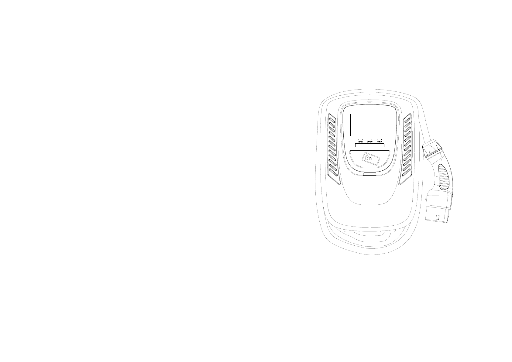
• The device is designed only for vehicles that are compatible with the Model 3 charging
standard.
• Do not use the charger if it is defective, appears cracked, frayed, broken or damaged.
• Do not attempt to open, disassemble, repair, tamper with, or modify the charger. Contact our
Customer Service for any requirement of repair.
• Do not use the charger when you are in the vehicle, or the charger is exposed to severe rain,
snow, or other severe weather.
• When transporting the charger, handle with care and do not drag or step on the device.
• Do not touch the charging connector terminal with sharp metallic objects for preventing
damage.
• Do not forcefully pull the charging cable, damage it with sharp objects, put fingers, or insert
foreign objects into any part of the charging connector.
• Risk of explosion. This device has arcing or sparking parts that should not be exposed to
flammable vapors.
• Risk of electric shock. Do not remove cover or attempt to open the enclosure of the device.
No user serviceable parts inside. Refer servicing to qualified service personnel.
• To reduce the risk of serious injury or death and damage to the charge, this device should be
installed, adjusted, and serviced by qualified electrical personnel familiar with the construction
and operation of this type of charger and the danger involved. Failure to observe this precau-
tion could result in death or severe injury.
• Incorrect installation and testing of the charger could potentially damage either the vehicle's
battery and/or the device itself. Any resulting damage is excluded from the warranty for the
device.
• Ensure that the charging cable is well positioned during charging so it will not be stepped on,
tripped over, or subjected to damage or stress.
• Do not use this charger with a frayed charging cable that has damaged insulation or any other
sign of damage.
• According to the local electrical requirements, confirm the wire diameter and wire type
corresponding to the current rating and the temperature rating must meet the requirements.
• Before starting the installation, turn off all power.
For safe use of electricity, please add circuit breaker protection in the input part of charging
pile, install certified type A RCD and circuit breaker (Schneider) upstream close to AC charger.
USER MANUAL
USER MANUAL
Circuit Breaker Options Table
AC Charger Output Amperage (A)
1-phase 3-phase
Circuit Breaker Options (A)
Circuit Breaker Model
16A32A
20A40A
32A
40A
A9F18420A9F18240 A9F18440

72mm
4-Φ9mm
122mm
LED Light
Indication
2. Basic Interface 3. Dimensions
Rear Notch
Charging Cable Inlet
LAN Cable Inlet
Charging Cable Inlet
250.0mm
130mm
350.0mm
USER MANUAL USER MANUAL

READY
CHARGE
CHARGE
Standby - Blue Light
The READY light stays steady in
standby mode.
Waiting for Charging - Green Light
After the vehicle connector is connected
to the vehicle inlet, the CHARGE light is
constantly lit
Charging - Green Light Flashing
The CHARGE light flashes while
charging.
4. Specification 5. Status Description of the Charger Indication Light
230VAC±10% / Single Phase 400VAC+10% / Three Phase
50/60 Hz
UVP, OVP, RCD, SPD, Ground Fault Protection
OCP, OTP, Control Pilot Fault Protection
IEC 62196-2 AC Charging Connector
-40°C to +70°C
-30°C to +50°C
95% RH Maximum
95% RH Maximum
LAN Version / Wi-Fi Version / 4G Version
10M/100M Base-T
GSM/3G/4G
5m
IP65
Wall-Mounted
≤ 2000 m
16/32A32A
Red, Green, Blue LED
Model Name EVC10 Version
Rated Input Voltage
Rated Output Current
AC Power Frequency
Input Protection
Output Protection
Output Interface
Storage Temperature
Operation Temperature
Relative Operation Humidity
Relative Storage Humidity
Version
RJ45 Cable lnlet*1
3G/4G Function*3
802.11 b/g/n
Wi-Fi Function*2
Cable Length
Protection Level
Installation Type
Altitude
Status Indication
*1 LAN Version or Wi-Fi Version or 4G Version
*2 Wi-Fi Version
*3 4G Version
USER MANUALUSER MANUAL

FAULT
AC Charger (With Charging Cable)
No. Product Name Quantity Note
1
1
1
2
4
Wall-Mounted Bracket
User Manual
M5 teeth screws
M6 Hexagonal Expansion Screws
RFID Card (RFID Version Only)
Fault - Red Light
The red light is lit while fault. Please
refer to "8.3 Error and Warning
Messages" for detailed information.
6. Packing List
7 Installation Instructions
7.1 Safety Requirements
• Be sure to preview the user manual and ensure local building and electrical codes are
reviewed before installing the AC charger.
• The AC charger should be installed by a qualified technician according to the user manual
and local safety regulations.
• Use appropriate protection when connecting to the main power distribution cable.
• Type B, C or D breaker with the rating current for table should be installed in the upstream
AC distribution box.
• Disconnect switch for each ungrounded conductor of AC input shall be provided by others.
USER MANUALUSER MANUAL
EVC10 Series (EU) - User Manual

7.2 Installation Steps
Step 1: Use screwdriver to loosen the 13 fixed screws on the rear of charger,
then remove the front cover (for 4G Version).
Step 2: Insert the SIM card according to the picture's instruction (for 4G Version).
Step 3: Tighten 13 screws on the front cover after the front cover is put back, the
recommended screw torque is 1.0 N.m (9.6 lbf.in) (for 4G Version).
USER MANUAL
USER MANUAL
2
3
4
5
6
7
8
9
10
11
12
13
1
2
3
4
5
6
7
8
9
10
11
12
13
1

7.3 Wiring
Output Amperage (A)
Output Amperage (A)
32A
32A
16A
20A 40A
40ACircuit Breaker Options (A)
11 12
Circuit Breaker Options (A)
Circuit Breaker Options table Circuit Breaker Options table
For safe use of electricity, please add circuit breaker protection in the input part
of charging pile. Connect the L lead to the grid L, connect the N lead to the grid N,
connect the PE lead to the grid PE (for Single Phase).
For safe use of electricity, please add circuit breaker protection in the input part
of charging pile. Connect the L1 lead to the grid L1, connect the L2 lead to the grid L2,
connect the L3 lead to the grid L3, connect the N lead to the grid N, connect the PE lead
to the grid PE (for Three Phase)
USER MANUAL
USER MANUAL

7.5 Wall-Mounted Bracket Installation
13 14
7.4 Tools and Materials Required
Tools required before installing the Wall-Mounted charger, gather the following tools:
• Wire stripper
• Crimpers for European terminals
• Phillips screwdriver for M5
• Slotted screwdriver for 4~5.5MM
• Adjustable Wrench M6
• Head gasket screw 10-10.5mm
• Voltmeter or digital multi-meter (for measuring AC voltage at the installation site)
• The inserting cable should meet the best waterproof performance. It is recommended to use
3 core/6mm cable for Single Phase / 5 core/6mm cable for three phase (XLPE or equivalent
cable) to pull the cable from the distribution box.
• Level ruler
• Pencil or marker
• Machine drill
Installation Instructions
“This device shall be mounted at a sufficient height from grade such that the height of the
storage means for the coupling device is located between 600mm (24 inches) and 1.2m (4
feet) from grade.”
Step 1:
• Set the positions of the 4 screw holes and drill them, with a diameter of 8mm and
a depth of 52mm.
• Use 4 sets expansion screw and M6 screw to fix the wall-mounted bracket on the wall.
Step 2: Align the rear notch of charger into the wall-mounted bracket and fit the screw
holes of the right and left side.
USER MANUAL USER MANUAL

15 16
Step 3:
Fix two M5 screws to complete the installation.
Overall outlook picture after installation:
Wall-mounted cable winding Optional cable hanging (optional accessory)
READY
● User authorization
● Connect to Vehicle Charging Inlet
● Charging Message
● Charging completed
8. Operating Instructions
8.1 Operating Procedures
8.2 Operating Steps
Step 1 / Standby Mode
After power-on, blue light (READY), green light (CHARGE) and red light (FAULT) all lit.
Enter standby mode and the blue light (READY) is steady on.
Step 2 / Tap the RFID Card
Please plug the charging connector into the vehicle charging inlet. When you tap the
RFID card first, it needs to complete the insertion of the charging connector within 120
seconds, otherwise you need to tap the RFID card again.
USER MANUAL USER MANUAL

CHARGE
17 18
Step 3 / Tap the RFID Card
Tap the RFID card to start the charging.
Step 4 / Charging
The green light (CHARGE) turns to flash automatically, charging is in process.
• If the red light (FAULT) is lit, plug the vehicle connector again.
• If red light is still lit, please refer to "Error and Warning Messages".
Step 5 / Charging Finished
When the charging is finished, the green light (CHARGE) is constantly lit, please
remove the plug.
8.3 Error and Warning Message
Remark
Auto Recover
Auto Recover
Auto Recover
Auto Recover
Auto Recover
Auto Recover
Auto Recover
Red
1 flashes followed by 3 sec pause
2 flashes followed by 3 sec pause
3 flashes followed by 3 sec pause
4 flashes followed by 3 sec pause
5 flashes followed by 3 sec pause
6 flashes followed by 3 sec pause
Flicker
Constantly Bright
Constantly Bright
Contact Customer Service
Status
Input OVP
Input UVP
Output OCP
OTP
RCD Abnormal
Ground Fault
Control Pilot Fault
MCU Self-Test Fail
Constantly Bright Contact Customer ServiceRCD Self-Test Fail
Constantly Bright Contact Customer ServiceRelay Self-Test Fail
Constantly Bright Contact Customer Service
RCD Abnormal Stop Charging
Constantly Bright Contact Customer ServiceOutput OCP Stop Charging
OTP Stop Charging
USER MANUAL
USER MANUAL

19 20
USER MANUAL
USER MANUAL
9. Maintenance and Repair
9.1 Daily Maintenance
Please keep the charger clean and keep the charge in a clean area with low humidity. Do not
install it in an environment near the sea, with high oil, high humidity or high dust.
• Avoid moisture or water in the charger. If there is water or moisture ingress into the charger, it
is necessary to immediately power off to avoid immediate danger, and notify the professional
personnel to carry out maintenance before next use.
• If there is any damage or dirt on the vehicle connector, charging cable, or vehicle connector
holder, please contact the maintenance personnel immediately.
• Please use the charger properly. Do not hit or press hard on the case. If the case is damaged,
please contact a professional technician.
• Avoid placing the charger near hot objects and at high temperature locations and away from
dangerous substances such as flammable gases and corrosive materials.
• Do not place external objects or heavy objects on the charger to avoid danger.
9.2 Maintenance Spares
• This charger is equipped with maintenance spares for maintenance use during and over the
warranty period. All warranty services and repairs shall be and performed by certified service
technicians authorized by Joint Technology. For details, please contact your local Joint Tech-
nology service partner or direct to our Customer Service.
9.3 Warranty and Maintenance
• The warranty period for this charger is three years.
• After the event of any repair or maintenance under the warranty period, if there is no purchase
to extend the warranty service, Joint Technology shall provide a three-month warranty period
for any subsequent paid repair work.
• During the warranty period for any malfunction caused by normal use according to the User
Manual and Service Instruction (to be determined by certified maintenance technicians of Joint
Technology), the product shall be repaired free of charge. Except for the following situations,
the charger shall be subject to the above warranty terms:
1. The warranty certificate cannot be provided or the contents of the warranty certificate are
modified or inconsistent with the label indication of the repaired product.
2. Those who are unable to provide valid proof of purchase.
3. Those who exceed the manufacturer's specified warranty period.
4. Those who damage the product due to not following the product service instruction for use,
maintenance and storage.
5. Damage or malfunction caused by foreign object entering.
6. Unauthorized repair, disassembly or modification.
7. Damage caused by force majeure (such as lightning, excessive voltage, earthquake, fire,
flood, etc.).
8. Malfunction and damage caused by other unavoidable external factors. Malfunction and
damage caused by improper use of equipment, such as water or other solutions entering into
the equipment.
9. Malfunction and damage caused by the grid power supply and voltage which is not specified
for use with the charger equipment.
• The above guarantees shall be made solely, and no other express or implied warranties shall
be made (including the implied warranties of merchant ability, particular and applicable reason-
ableness and adaptability, etc.) whether in the contract, civil negligence, or other aspects, the
Company shall not be responsible for any special, incidental or consequential damages.
Table of contents