3 Description
Cala KNX M-T CH push button • Version: 25.04.2022 • Technical changes and errors excepted.
1. Description
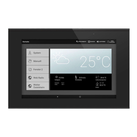
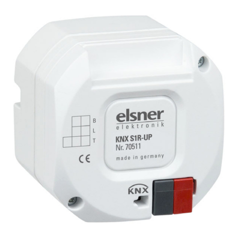
The Cala KNX M-T CH push button has touch-sensitive buttons, with which func-
tions in the KNX building bus system can be called, such as switch lights and devices,
dim, activate drives, send values, scenarios. A white LED is integrated into each touch
button, the behaviour of which can be adjusted.
A temperature sensor is integrated into Cala KNX M-T CH. An external temperature
reading can be received via the bus and processed with its own data to create a total
temperature (mixed value).
Communication objects can be connected by AND and OR logic gates.
The device is supplemented with a frame of the switch series used in the building, and
thus fits seamlessly into the interior fittings.
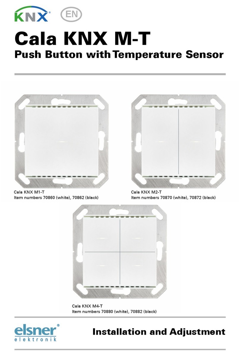
Cala KNX M1-T CH functions:
•1Touch bus button, can be configured as switch, selector switch, dimmer,
blind (position and slats up/stop OR down/stop), shutters (up/down/stop),
awning (in/out/stop), window (closed/open/stop), as 8 or 16-bit encoder or for
scenario recall/storage
Cala KNX M2-T CH functions:
•2 Touch bus button, can be configured as switch, selector switch, dimmer,
for operating drives, as 8 or 16-bit encoder or for scenario recall/storage
•Area function when touching both push buttons. Can be configured as
switch, selector switch, as 8 or 16 bit encoder or for scenario recall
Cala KNX M4-T CH functions:
•4 Touch bus button, can be configured as switch, selector switch, dimmer,
for operating drives, as 8 or 16-bit encoder or for scenario recall/storage
•Area function when touching two or more push buttons. Can be configured
as switch, selector switch, as 8 or 16 bit encoder or for scenario recall
Function of all models:
•OneLED per touch area. On for object value = 1 / Off for object value = 0, On
after pressing button for settable time or always off. Settable, as to whether
LED flashes at block object value = 1
•Temperature measurements. Mixed value from own measured value and
external values (proportion can be set by percentage)
•2 AND and 2 OR logic gates each with 4 inputs. All switching events as well
as 8 logic inputs (in the form of communications objects) can be used as inputs
for the logic gates. The output from each gate can be configured optionally as
1-bit or 2 x 8-bit
Configuration is made using the KNX software as of ETS 5. The product file can be
downloaded from the ETS online catalogue and the Elsner Elektronik website on
www.elsner-elektronik.de in the “Service” menu. There you will also find the pro-
duct manual.


