Elsteam KT Series User manual

924KTE4.01 - 05/2021
KT Series
Immersed electrode humidiers

CONTENTS
924KTE4.01 - KT series humidiers 05/2021
| 2 |
IMPORTANT INFORMATION.............................................................................................................. 4
IMPORTANT SAFETY INFORMATION................................................................................................ 5
SAFETY INFORMATION RELATING TO THE PRODUCT..................................................................... 6
1. INTRODUCTION............................................................................................................................... 7
1.1 Description.............................................................................................................................................. 7
1.2 Applications ............................................................................................................................................ 7
1.3 Main features ......................................................................................................................................... 7
1.3.1 Features of electronic control...................................................................................................................7
1.4 Accessories ............................................................................................................................................ 8
2. TECHNICAL DATA............................................................................................................................ 9
2.1 Technical specications........................................................................................................................ 9
3. DELIVERY OF PRODUCT................................................................................................................ 10
3.1 Checking the packaging.......................................................................................................................10
3.1.1 Opening the packaging..............................................................................................................................10
3.1.2 Checking the contents ..............................................................................................................................10
4. DIMENSIONS AND MECHANICAL ASSEMBLY........................................................................... 11
4.1 Dimensions............................................................................................................................................11
4.2 Minimum installation distances..........................................................................................................11
4.3 Installation............................................................................................................................................12
4.3.1 Installation instructions...........................................................................................................................12
5. INSTALLATION .............................................................................................................................. 13
5.1 Humidier parts ...................................................................................................................................13
5.1.1 Top ..............................................................................................................................................................13
5.1.2 Bottom ........................................................................................................................................................13
5.2 Water connections...............................................................................................................................13
5.2.1 Characteristics of water ..........................................................................................................................13
5.3 Water discharge system......................................................................................................................13
5.3.1 Characteristics of tting ..........................................................................................................................14
5.4 Steam distribution in an AHU or duct .................................................................................................14
5.4.1 Permitted positioning of the distributor in the duct ..............................................................................15
5.4.2 Examples of distributor installation in the duct .....................................................................................16
5.4.3 Distributing steam in the room ................................................................................................................17
6. ELECTRICAL CONNECTIONS........................................................................................................ 18
6.1 Before starting .....................................................................................................................................18
6.2 Connection best practices ..................................................................................................................18
6.2.1 Wiring best practices................................................................................................................................18
6.2.2 Replacing fuses - Fuse holder ..................................................................................................................20
6.2.3 Replacing fuses - Control board...............................................................................................................21

CONTENTS
924KTE4.01 - KT series humidiers 05/2021
| 3 |
6.3 Wiring diagrams ...................................................................................................................................22
6.3.1 Connection with ON/OFF humidistat .......................................................................................................22
6.3.2 Connection with humidistat with voltage output, ON/OFF and proportional......................................22
6.3.3 Connection with humidistat with resistive output .................................................................................23
6.3.4 Connection with humidistat which suspends humidication when ventilation is suspended...........23
7. USER INTERFACE AND INITIALISATION ................................................................................... 24
7.1 How the LEDs work...............................................................................................................................24
7.2 Switching on and starting up...............................................................................................................25
8. OPERATION.................................................................................................................................... 26
8.1 Regulating and calibrating the potentiometers ................................................................................26
8.2 Manual water discharge .....................................................................................................................26
9. MAINTENANCE.............................................................................................................................. 27
9.1 Introduction..........................................................................................................................................27
9.2 Periodical cleaning of the product and parts....................................................................................28
9.3 Cleaning the boiler ...............................................................................................................................29
9.4 Cleaning the optional stainless steel drain tank (accessory) 29
9.5 Replacing the boiler .............................................................................................................................29
9.6 Installing the boiler..............................................................................................................................29
10. SPARE PARTS .............................................................................................................................. 30
10.1 Hydraulics...........................................................................................................................................30
10.2 Electrics ..............................................................................................................................................31
11. WHAT TO DO IF............................................................................................................................ 32
12. WIRING DIAGRAMS................................................................................................................... 33
12.1 Models KT3 .........................................................................................................................................33
12.2 Models KT5-400..................................................................................................................................34
12.3 Models KT10-230 ...............................................................................................................................35
12.4 Models KT10-400 / KT20-400 ...........................................................................................................36
12.5 Models KT20-230 ...............................................................................................................................37
12.6 Models KT30-400 ...............................................................................................................................38
12.7 Models KT40-400 / KT60-400 ...........................................................................................................39

924KTE4.01 - KT series humidiers 05/2021
| 4 |
IMPORTANT INFORMATION
Liability and residual risks
ELSTEAM assumes no liability for any damage caused by the following (by way of example; this is not an exhaustive list):
• Installation/useforpurposesotherthanthosespeciedand,inparticular,notadheringtothesafetyprovisionssetout
by current regulations in the country in which the product is installed and/or contained in this manual;
• Useinappliancesthatdonotguaranteesufcientprotectionagainstelectricshocks,wateranddustwithinthe
installation conditions created;
• Useinappliancesthatallowaccesstohazardouspartswithouttheuseofakeyedortooledlockingmechanismwhen
accessing the instrument;
• Tampering and/or modifying the product;
• Installation/use in appliances which do not comply with current regulations in the country in which the product is
installed.
The customer/manufacturer is responsible for ensuring their machine complies with these regulations.
ELSTEAM’s responsibility is limited to the correct and professional use of the product in accordance with regulations and the
instructions contained in this manual and other product support documents.
TocomplywithEMCstandards,observealltheelectricalconnectioninstructions.Asitdependsonthewiringconfigurationas
wellastheloadandtheinstallationtype,compliancemustbeverifiedforthefinalmachineasspecifiedbytherelevantproduct
standard.
Disclaimer
This document is the exclusive property of ELSTEAM. It contains a general description and/or a description of the technical
specifications for the features offered by the products listed herein. This document should not be used to determine the
suitability or reliability of these products in relation to specific user applications. Each user or integration specialist should
conducttheirowncompleteandappropriateriskanalysis,inadditiontocarryingoutaproductevaluationandtestinrelation
to its specific application or use. Users can send us comments and suggestions on how to improve or correct this publication.
Neither ELSTEAM nor any of its associates or subsidiaries shall be held responsible or liable for improper use of the
information contained herein.
ELSTEAMhasapolicyofcontinuousdevelopment,thereforereservestherighttomakechangesandimprovementstoany
product described in this document without prior notice.
The images in this document and other documentation supplied with the product are provided for illustrative purposes only and
may differ from the product itself.
The technical data in this manual is subject to change without prior notice.
Terms and Conditions of use
Permitted use
The device must be used for humidification only.
Thedevicemustbeinstalledandusedinaccordancewiththeinstructionsprovidedand,inparticular,hazardouslivepartsor
high pressure water must not be accessible under normal conditions.
The device must be suitably protected from water and dust with regard to its application and must also only be accessible with
the aid of a tool.
Only qualified personnel may install the product or perform technical support procedures on it.
The customer must only use the product as described in the documentation relating to that product.
Prohibited use
Any use other than those described in the "Permitted use" section and in the product support documentation is prohibited.
Disposal
The device must be disposed of according to local regulations governing the collection of electrical and
electronic equipment.
Consider the environment
Thecompanystrivestorespecttheenvironment,takingaccountofcustomerrequirements,technological
innovations in terms of materials and the expectations of the community to which we belong. ELSTEAM places great
importanceonrespectingtheenvironment,encouragingallassociatestobecomeinvolvedwithcompanyvaluesand
guaranteeingsafe,healthyandfunctionalworkingconditionsandworkplaces.
Please consider the environment before printing this document.

924KTE4.01 - KT series humidiers 05/2021
| 5 |
IMPORTANT SAFETY INFORMATION
Readthisdocumentcarefullybeforeinstallationandtakeallprecautionsbeforeusingthedevice.Onlyusethedevicein
accordance with the methods described in this document. The following safety messages may be repeated several times in
thedocument,toprovideinformationregardingpotentialhazardsortoattractattentiontoinformationwhichmaybeusefulin
explaining or clarifying a procedure.
SYMBOLS
Thissymbolisusedtoindicateariskofelectricshock.
Itisasafetyindicationandassuch,shouldbeobservedtoavoidpotentialaccidentsorfatalities.
Thissymbolisusedtoindicateariskofseriouspersonalinjury.
Itisasafetyindicationandassuch,shouldbeobservedtoavoidpotentialaccidentsorfatalities.
Thissymbolisusedtoindicateariskofseriouspersonalinjury/burns.
Itisasafetyindicationandassuch,shouldbeobservedtoavoidpotentialaccidentsorfatalities.
SAFETY MESSAGES
DANGER
DANGER indicatesasituationofimminentdangerwhich,ifnotavoided,will result in death or serious injury.
WARNING
WARNING indicatesasituationofimminentdangerwhich,ifnotavoided,may result in death or serious injury.
CAUTION
CAUTION indicatesapotentiallyhazardoussituationwhich,ifnotavoided,could cause minor or moderate injury.
NOTICE
NOTICE indicates a situation not related to physical injuries but which
,ifnotavoided,
could damage the equipment.
N.B.:Themaintenance,repair,installationanduseoftheequipmentmustonlybeentrustedtoqualifiedpersonnel.
QUALIFIED PERSONNEL
Only suitably trained and experienced personnel capable of understanding the content of this manual and all documentation
regardingtheproductareauthorisedtoworkonandwiththisequipment.Furthermore,thepersonnelmusthavecompleted
coursesinsafetyandmustbeabletorecogniseandpreventtheimplieddangers.Thepersonnelmusthavesuitabletraining,
knowledgeandexperienceatatechnicallevel,andbecapableofanticipatinganddetectingpotentialriskscausedbyusing
theproduct,aswellaschangingthesettingsandmodifyingthemechanical,electricandelectronicequipmentfortheentire
systeminwhichtheproductisused.Allpersonnelworkingonandwiththeproductmustbeentirelyfamiliarwiththerelevant
standardsanddirectives,aswellassafetyregulations.

924KTE4.01 - KT series humidiers 05/2021
| 6 |
SAFETY INFORMATION RELATING TO THE PRODUCT
Beforecarryingoutanyworkontheequipment,readtheseinstructionscarefully,makingsureyouunderstandeverything.
DANGER
RISK OF ELECTRIC SHOCK, EXPLOSION OR ELECTRIC ARC
• Only use electrically insulated measuring devices and equipment.
• Do not install the equipment while the power supply is connected.
• Switchoffallequipment,includingconnecteddevices,beforeremovinganycoversorhatchesandbeforeinstallingor
uninstallinganyaccessories,hardware,cablesorwires.
• Usetherequiredsafetyinterlocks(disconnectors)ofasuitablesizebetweenthepowersupplyandthehumidifier.
• Alwaysuseacorrectlycalibratedvoltmetertocheckthesystemisswitchedoff.
• Themaintenance,repair,installationanduseoftheequipmentmustonlybeentrustedtoqualifiedpersonnel.
• Do not touch the unshielded components or the terminals while they are live.
• Donotopen,disassemble,repairormodifytheproduct.
• Do not expose the equipment to liquids or chemicals.
• Makesuretheequipmentisproperlyearthed.
• Before applying voltage to the equipment:
• Makesureallprotectiveelements,suchascovers,hatchesandgrilles,arefittedand/orclosed.
• Checkallwiringconnections.
DANGER
RISK OF ELECTRIC SHOCK AND FIRE
• Do not use the device with loads greater than those indicated in the technical specifications.
• Do not exceed the temperature and humidity ranges indicated in the technical specifications.
• Usetherequiredsafetyinterlocks(disconnectors)ofasuitablesizebetweenthepowersupplyandthehumidifier.
• Only use cables with a suitable cross-section as indicated in the section “Wiring best practices”.
WARNING
MALFUNCTIONING OF THE EQUIPMENT
• Performthewiringcarefully,incompliancewithelectromagneticcompatibilityandsafetyrequirements.
• Carry out a full start-up test.
• Makesurethewiringiscorrectforthefinalapplication.
• Minimise the length of the connections as much as possible and avoid winding the cables around electrically connected
parts.
• Beforeapplyingthepowersupply,checkallthewiringconnections.
• Do not connect wires to unused terminals and/or to terminals labelled “No connection “(N.C.)”.
Thehumidifierproducessteamat100°C(212°F)anddischargeswaterwithatemperatureofapproximately98°C(208.4°F).
WARNING
HOT STEAM
Do not touch the equipment when it is in operation.
WARNING
RISK OF BURNS
Beforecarryingoutanyworkonthesystem,disconnectthehumidifierandwaituntilithascooleddown(<50°C(122°F)).
WARNING
REGULATORY NON-COMPLIANCE
Makesurealltheequipmentusedandthedesignedsystemscomplywithcurrentlocal,regionalandnationalregulationsand
standards.

924KTE4.01 - KT series humidiers 05/2021
| 7 |
1. INTRODUCTION
1.1 Description
The KT series is a range of immersed electrode humidifiers by ELSTEAM.
The humidifiers in the KT series generate humidity (steam) when a current is applied to two or more electrodes immersed in tap
water,causingthewatertoboil.
Thesteamiscontrolledbymodulatingtheintensityofthecurrenttransferredtothewaterbytheimmersedelectrodes,soby
indirectly controlling the boiling water.
Steam is introduced into the room through a special flexible hose and a steam distributor in stainless steel and engineering
plastic (steam introduced into an AHU - air handling unit or an air conditioning duct) or a steam blower (steam introduced into
room).
1.2 Applications
The KT seriesismainlyusedwhensterilesteamisneeded,suchasin:
• Hospitals;
• Healthcare facilities;
• Commercialbuildings(ofces,factories,etc...)or;
• Wellness centres.
1.3 Main features
• Isothermalhumidier;
• Sterilesteam(atatemperatureofapprox.100°C(212°F));
• Automatic boiler cleaning;
• Automatic descaling of electrodes and boiler (reusable);
• Variablesteamoutput(3...60kg/h);
• Built-inelectroniccontrolusingON/OFFsignalor0...10V(proportional);
• Protectionagainstwaterescapingonthesteamside(oatingballwhichstopswaterleakingintothesteamsupplypipe);
• Stainlesssteeldrainagetankavailableonrequest.
1.3.1 Features of electronic control
• Proportional (logarithmic) control of steam production:
• Highlyefcient;
• Quickresponsetochangesinrequest;
• Accurate control of steam production.
• Automatic electrode and boiling cleaning system (international patent):
• Less maintenance required;
• High performance;
• Prolongs the life of the electrodes and boiler.
• Automatic boiler drainage:
• Removes any limescale which collects in the manifold sleeve;
• Prolongs the life of the boiler.
• LED signalling of operating status:
• Operating status always under control;
• Automatic fault analysis.

924KTE4.01 - KT series humidiers 05/2021
|8|
1.4 Accessories
The following accessories are available for the immersed electrode humidifiers in the KT series:
P/n Description
EHSD040 Linearsteamdistributor,400mm(15.75in.)
EHSD060 Linearsteamdistributor,600mm(23.62in.)
EHSD080 Linearsteamdistributor,800mm(31.49in.)
EHSD100 Linearsteamdistributor,1000mm(3.28ft)
EHSD130 Linearsteamdistributor,1300mm(4.26ft)
EHSD160 Linearsteamdistributor,1600mm(5.25ft)
EHSD200 Linearsteamdistributor,2000mm(6.56ft)
EHSDSP0 Linearsteamdistributor,lengthonrequest
EHSDY00
Yfitting,diameter38mm
EHSR0107
Steam blower for room
TV Special pipe fitting that connects the humidifier and distributor
VI Waterdrainagetank
EVHP523 Humidity probe 4-20 mA
EV3411M7 Universalcontrollerwith1outlet,powersupply230Vac
EVTPNW30F200 NTCtemperatureprobe,IP68
0031000048 Female3/4"Gflexiblehosetofeedwater
1240000004 Alarm electronic board

924KTE4.01 - KT series humidiers 05/2021
|9|
2. TECHNICAL DATA
2.1 Technical specifications
Description M.U. KT3 KT10-230 KT20-230 KT5 KT10 KT20 KT30 KT40 KT60
Steam production
Production capacity kg/h 3 10 20 5 10 20 30 40 60
Maximum pressure
MPa
(mmH2O)
0.002 (200)
Pipe connection external
diameter mm (in.) 40 (1.57)
Steam distribution
Number of linear distributors
that can be connected --- 1 1 2 1 1 1 1 2 2
Number of steam blowers that
can be connected --- 1 1 / 1 1 / / / /
Electrical properties
Power consumption kW 2.25 7.5 15 3.75 7.5 15 22.5 30 45
Power supply Vac,Hz 230V,50Hz 400V,50Hz
Phases Ph 1 3 3 2 3 3 3 3 3
Current per phase A 10 19 38 9 11 22 32 43 65
Water properties
Inlet water quality --- See "5.2.1 CHARACTERISTICS OF WATER" ON PAGE 13
Inlet water conductivity μS*cm 70…1250
Inlet water hardness °f 5...50
Inlet water pressure
MPa/bar
0.2...1/2...10
Inlet water connection --- 3/4"GAS
Water drain external dimensions
mm (in.) 42 (1.65)
General characteristics
Dimensions mm (in.) See "4.1 DIMENSIONS" ON PAGE 11
Weight kg 15 25 15 25
Hydraulic unit IP protection --- 20
Regulation
Type of controller --- Built-in
Command signal --- Proportional(0-10V)orON-OFF
Compliance
CE certification --- √

924KTE4.01 - KT series humidiers 05/2021
| 10 |
3. DELIVERY OF PRODUCT
3.1 Checking the packaging
• Checkthepackagingisintact;
• Checkthehumidierisintactupondeliveryandimmediatelynotifythecarrier,inwriting,ofanydamagethatmaybedue
to careless or improper transport (accept the goods subject to inspection).
3.1.1 Opening the packaging
• Movethepackagingtowherethehumidieristobeinstalled;
• Openthecardboardpackagingandremovetheprotectivepolystyrenecorners;
• Pullthehumidierout.
3.1.2 Checking the contents
Thepackagingcontains:
• KT serieshumidier;
• Operation and maintenance manual;
• Pipettingthatfeedswaterfromthemainstothehumidier’swaterloadsolenoidvalve;
• Hexkeytoopenthecabinet.

924KTE4.01 - KT series humidiers 05/2021
| 11 |
4. DIMENSIONS AND MECHANICAL ASSEMBLY
4.1 Dimensions
680 (26.77)
210 (8.26)
610 (21.01)
370 (14.57)
210 (8.26)
680 (26.77)
mm (in.)
KT40 400
KT60 400
KT10 ...KT5
KT10...KT3
KT5
Fig. 1. Dimensions
4.2 Minimum installation distances
WARNING
MALFUNCTIONING OF THE EQUIPMENT
• The humidifier must be installed where the minimum distances from all nearby structures and equipment can be
guaranteed,asshowninthismanual.
• Install all the equipment in accordance with the technical specifications given in the respective documentation.
mm (in.)
KT40 400
KT60 400
KT10 ...KT5
KT10...KT3
KT5
300 (11.81)
>1000 (39.36)
>1000 (39.36)
300 (11.81)300 (11.81) 300 (11.81) 300 (11.81)
300 (11.81)
Fig. 2. Minimum installation distances

924KTE4.01 - KT series humidiers 05/2021
| 12 |
4.3 Installation
2
1
3
4
2.2
2.1
56
Fig. 3. Installation instructions
N.B.: Installation of models KT40 / KT60 is the same as above.
4.3.1 Installation instructions
DANGER
RISK OF ELECTRIC SHOCK, EXPLOSION OR ELECTRIC ARC
Makesuretheequipmentisproperlyearthed.
NOTICE
IRREGULAR INSTALLATION
Usebracketswithaminimumload-bearingcapacityof80kgwheninstallingthehumidifier.
• OpenthepanelsofthehumidierbyremovingtheheadlessscrewswiththeSW2.5hexkey;
• Removethepanelsoneatatime,pullingthemtowardsyoufromthebottomandliftingthemup;
• Removethehumidierfromthepolystyrene;
• Hookthehumidierontothebracketsonthewallusingtheslotsattherearofthehumidier.

924KTE4.01 - KT series humidiers 05/2021
| 13 |
5. INSTALLATION
5.1 Humidifier parts
5.1.1 Top
• Steam outlet;
• Male3/4"GASconnectorforwatersupply.
5.1.2 Bottom
• Water outlet to connect to sewer system;
• Strain relief cable gland for power supply wiring;
• Strain relief cable gland for wiring of regulation board.
5.2 Water connections
You will need the following components to plumb in the humidifier:
• An intercept tap;
• Asupplementaryltertotheonealreadyinthesolenoidvalve;
• A pressure reducer (if the pressure of the mains water exceeds 1 MPa (10 bar)).
N.B.:Ifapressurereducerisused,makesureitiseffectiveanddoesnotcauseadrasticreductioninpressurewhenthemains
pressure is very low.
NOTICE
MALFUNCTIONING OF THE EQUIPMENT
• The feed water must have a minimum pressure of 0.2 MPa (2 bar).
• Connect the solenoid valve to the mains using the flexible hose supplied to reduce water hammers in the hose to the
humidifier.
• Duringinstallation,becarefulnottodamagetheplasticthreadofthesolenoidvalve.
• Whenmakingthewaterconnections,itmustalwaysbepossibletoaccessthemechanicalfilterinthewaterloadsolenoid
valve for cleaning.
5.2.1 Characteristics of water
• Water pressure between 0.2...1 MPa (2...10 bar);
• Temperaturebetween1...50°C(33.8...122°F);
• Conductivitybetween75...1250μS/cm;
• Maximum water hardness between 5...50 °f.
N.B.:Ifwaterisharderorifthereismoreorganicresidueinit,thehumidierwillstilloperatecorrectlybutitmustbeserviced
more regularly.
Dos
• Flushwaterintothedrainforacoupleofhoursbeforemakingthenalconnection.
• Checktheconditionoftherubbercouplingregularlytopreventproblemsandwaterleakingintotheroom.
Don’ts
• Softenthewater.Ifthewaterhardnessisabove50°forifitissuchthattheboilerrequiresregularmaintenance,use
demineralisedwatermixedwithtapwaterinapercentagethatensuresaminimumconductivityof200μS/cmanda
hardness of at least 10 °f.
NOTICE
MALFUNCTIONING OF THE EQUIPMENT
• Do not use softened water.
• Oncethehumidifierhasbeeninstalled,flushthepipeswiththeremainingwatertopreventblockingthefilter.
• Checkallthepartsofthehumidifierareintact.
• Ifevenonepartofthehumidifierisdamaged,suspendinstallation.
5.3 Water discharge system
Asthishumidifierhasanautomaticboilercleaningfunction,thewateroutletmusthaveacapacityofatleast10litresinafew
seconds (maximum 1 l/s).
NOTICE
MALFUNCTIONING OF THE EQUIPMENT
Sizetheoutletpipetopreventobstructionsorblockagesduringtheautomaticcleaningcycle.

924KTE4.01 - KT series humidiers 05/2021
| 14 |
5.3.1 Characteristics of fitting
• Minimum diameter 40 mm (1.57 in.);
• Maximumradiusofcurvature300mm(0.98ft.);
• Minimum average slope of 45° with no siphons.
Ifthesecharacteristicscannotberespected,abasinmust
be placed at the bottom of the humidifier to collect water and
limescale (p/n VI) (contact ELSTEAM’s sales office for more
information).
Features of basin
• Drainage pipe with siphon to collect limescale.
NOTICE
MALFUNCTIONING OF THE EQUIPMENT
Ifthewaterisharderthan40°f,thebasinmustbechecked
and cleaned at least twice a year.
Minima 45°
Fig. 4. Drainage pipe
If the water hardness is the same as indicated in the section "5.2.1 CHARACTERISTICS OF WATER" ON PAGE 13,
,thebasincanbe
cleaned once a year.
Ifthedrainagesystem-orthebasin-ismadeofanelectricallyconductivematerial,asasafetymeasureitmustbeconnected
to the earthing of the electrical system.
DANGER
RISK OF ELECTRIC SHOCK
Ifthebasinismadeofanelectricallyconductivematerial,eartheitherthebasinorthedrainagesystem.
Theoutletwatercanreachatemperatureof98°C(208.4°F)orhigher.
WARNING
RISK OF BURNS
• Beforedrainingwater,makesureyouarewearingallthenecessarypersonalprotectiveequipment(PPE).
• Do not touch the equipment during draining.
5.4 Steam distribution in an AHU or duct
The humidifier must be connected to a stainless steel steam distributor with a fixing flange in engineering plastic in order to
distribute steam in the ventilation system.
The steam distributor must be installed:
• Vertically;
• At least one metre from the top of the duct;
• At the bottom of the duct (so the steam can mix properly with the air);
• Higherthanthehumidieroutlet;
• Ascloseaspossibletothehumidier(topreventreducedefciency).
Thesectionoftheductwherethesteamdistributorisinstalledmustbeinsulated,waterproofandhaveadrainatthebottom.
The insulated pipe fitting between the humidifier and the distributor must not be fitted with siphons and must always slope
down towards the humidifier to ensure the condensate runs freely in the machine.
WARNING
MATERIAL DETERIORATION
• The special steam piping must be fixed to the boiler and stainless steel ramp with stainless steel ties.
• Only use material suitable for the intended use.

924KTE4.01 - KT series humidiers 05/2021
| 15 |
5.4.1 Permitted positioning of the distributor in the duct
Horizontal installation
Fig. 5. Horizontal installation - 1 distributor
Fig. 6. Horizontal installation - 2 distributors
Vertical installation
Fig. 7. Vertical installation - 1-2 distributors

924KTE4.01 - KT series humidiers 05/2021
| 16 |
Horizontal installation - Wide duct
Fig. 8. Horizontal installation with wide duct - 2 distributors
5.4.2 Examples of distributor installation in the duct
Description Example
Installation example no. 1
Distributorisinstalledinahorizontalduct,positioned
higher than the humidifier.
Direction of air flow is not relevant.
Installation example no. 2
Distributor is installed in a vertical duct.
Direction of air flow is not relevant.
Installation example no. 3
Distributorisinstalledverticallyinahorizontalduct,
positioned higher than the humidifier.
Direction of air flow corresponds to the slope of the
ramp.

924KTE4.01 - KT series humidiers 05/2021
| 17 |
Description Example
Installation example no. 4
Distributorisinstalledinahorizontalduct,positioned
lower than the humidifier.
Example of incorrect installation
Itisimportanttoavoidcondensationpocketsinthe
supply pipe.
5.4.3 Distributing steam in the room
A steam blower p/n ESR010700 mustbeinstalledifsteamistobedistributedintheroomwithoutusingventilationducts.For
moreinformation,visitwww.elsteam.it.
Thesteamblowermustbepositionedhorizontally,withthedistributionholesaimedupwards,atleastonemetrefromthe
ceiling and walls.
WARNING
RISK OF BURNS
The steam blower must be installed so it is accessible to qualified personnel only.
WARNING
HOT STEAM
Do not touch the equipment when it is in operation.
Itmustbepositionedatleastonemetrefromtheceiling(3.28ft.).
Steam blower power supply
Steam blowers:
• Single-phase 230 Vac models: Powered directly by the fuse holder.
• Three-phase models: Powered directly by the 230 Vac mains voltage.

924KTE4.01 - KT series humidiers 05/2021
|18|
6.1 Before starting
Read this manual carefully before installing the equipment.
Inparticular,thesafetyinstructions,electricalrequirementsandcurrentregulationsforthemachineortheprocessinwhich
this device is involved must be observed.
The use and application of the information contained herein require experience in the design and installation of humidification
systems.Onlytheuser,systemintegratorormachinebuildercanbeawareofalltheconditionsandfactorspresentduringthe
installation,configuration,operationandmaintenanceofthemachineorprocess,andcanthereforedeterminetheassociated
automationequipmentandtherelatedsafetiesandinterlockswhichcanbeeffectivelyandproperlyused.Whenselecting
automationandcontrolequipmentandanyotherrelatedequipmentorsoftwareforaparticularapplication,alwaysconsider
alltheapplicablelocal,regionalornationalstandardsand/orregulations.
DANGER
RISK OF ELECTRIC SHOCK, EXPLOSION OR ELECTRIC ARC
• Only use electrically insulated measuring devices and equipment.
• Do not install the equipment while the power supply is connected.
• Switchoffallequipmentandremovethepowerfuses,includinganyconnecteddevices,beforeremovinganycoversor
hatches,orbeforeinstallingoruninstallingaccessories,hardware,cablesorwires.
• Usetherequiredsafetyinterlocks(disconnectors)ofasuitablesizebetweenthepowersupplyandthehumidifier.
• Alwaysuseacorrectlycalibratedvoltmetertocheckthesystemisswitchedoff.
• Themaintenance,repair,installationanduseoftheequipmentmustonlybeentrustedtoqualifiedpersonnel.
• Do not touch the unshielded components or the terminals while they are live.
• Donotdisassemble,repairormodifytheproduct.
• Do not expose the equipment to liquids or chemicals.
• Makesuretheequipmentisproperlyearthedandifitisnot,earthit.
• Before applying voltage to the equipment:
• Makesureallprotectiveelements,suchascovers,hatchesandgrilles,arefittedand/orclosed.
• Checkallwiringconnections.
WARNING
REGULATORY NON-COMPLIANCE
Makesurealltheequipmentusedandthedesignedsystemscomplywithcurrentlocal,regionalandnationalregulationsand
standards.
6.2 Connection best practices
6.2.1 Wiring best practices
DANGER
RISK OF ELECTRIC SHOCK AND FIRE
• Do not use the device with loads greater than those indicated in the technical specifications.
• Do not exceed the temperature and humidity ranges indicated in the technical specifications.
• Usetherequiredsafetyinterlocks(disconnectors)ofasuitablesizebetweenthepowersupplyandthehumidifier.
• Only use cables with a suitable cross-section as indicated in the section “Wiring best practices”.
Whenwiringthehumidifiers,observethefollowinginstructions:
• Makesuretheoperatingenvironmentandconditionsfallwithinthespeciedvalues.
• Usecablesofthecorrectdiameter,suitedtothevoltageandcurrentrequirements.
DANGER
LOOSE WIRING CAN RESULT IN ELECTRIC SHOCK AND OVERHEATING
Tighten connections in compliance with the technical specifications for torque values.
WARNING
MALFUNCTIONING OF THE EQUIPMENT
• Performthewiringcarefully,incompliancewithelectromagneticcompatibilityandsafetyrequirements.
• Carry out a full start-up test.
• Makesurethewiringiscorrectforthefinalapplication.
• Minimise the length of the connections as much as possible and avoid winding the cables around electrically connected parts.
• Beforeapplyingthepowersupply,checkallthewiringconnections.
• Do not connect cables to unused terminals and/or to terminals labelled “No connection “(N.C.)”.
6. ELECTRICAL CONNECTIONS

924KTE4.01 - KT series humidiers 05/2021
|19|
WARNING
REGULATORY NON-COMPLIANCE
Makesurealltheequipmentusedandthedesignedsystemscomplywithcurrentlocal,regionalandnationalregulationsand
standards.
Suitable wiring for power supply
Pitch 17,8 mm (0.70 in.)
Ø 3.5 mm (0.14 in.)
mm2
AWG
No. of conductors
2.5 2.5 2.5
13 13 13
3
mm
in.
7
0.28 C2,5
22.12
N•m
lb-in
Fig. 9. Suitable wiring for power supply - KT3
Pitch 17,8 mm (0.70 in.)
Ø 3.5 mm (0.14 in.)
mm2
AWG
No. of conductors
1.51.5 1.5
15 15 15
4
mm
in.
7
0.28 C2,5
22.12
N•m
lb-in
Fig. 10. Suitable wiring for power supply - KT5
Pitch 17,8 mm (0.70 in.)
Ø 3.5 mm (0.14 in.)
mm2
AWG
No. of conductors
4
mm
in.
7
0.28 C2,5
22.12
N•m
lb-in
2.5 2.5 2.5
13 13 13
Fig. 11. Suitable wiring for power supply - KT10 400 V
Pitch 17,8 mm (0.70 in.)
Ø 3.5 mm (0.14 in.)
mm2
AWG
No. of conductors
6
9
6
9
6
9
4
mm
in.
7
0.28 C2,5
22.12
N•m
lb-in
Fig. 12. Suitable wiring for power supply - KT10 230 V
Pitch 17,8 mm (0.70 in.)
mm2
AWG
No. of conductors
16
5
4
16
5
16
5
mm
in.
7
0.28
KT20 400
KT20 230 V / KT30
Ø 3.5 mm (0.14 in.)CN•m
lb-in
Ø 3.5 mm (0.14 in.)C3
26.55
N•m
lb-in
2,5
22.12
Fig. 13. Suitable wiring for power supply - KT20 400 V / KT20 230 V / KT30
Pitch 17,8 mm (0.70 in.)
mm2
AWG
No. of conductors
25
7
4
25
7
25
7
mm
in.
7
0.28
KT40
Ø 3.5 mm (0.14 in.)C4
35.40
N•m
lb-in
Fig. 14. Suitable wiring for power supply - KT40
Pitch 17,8 mm (0.70 in.)
Ø 3.5 mm (0.14 in.)
mm2
AWG
No. of conductors
35 + 25 35 + 25 35 + 25
2 + 32+ 32 + 3
3 (35) + 1 (25)
mm
in.
7
0.28 C4
35.40
N•m
lb-in
Fig. 15. Suitable wiring for power supply - KT60
N.B.: For models KT3 / KT5 / KT10 / KT10 230 / KT20wiringisdirectlyatthefuseholder,whilefortheothermodelsitis
directly at the disconnector.

924KTE4.01 - KT series humidiers 05/2021
| 20 |
Suitable protective devices for power supply
DANGER
RISK OF ELECTRIC SHOCK
• Switchoffallequipment,includinganyconnecteddevices,beforeremovinganycoversorhatches,orbeforeinstallingor
uninstallingaccessories,hardware,cablesorwires.
• Alwaysuseacorrectlycalibratedvoltmetertocheckthesystemisswitchedoff.
Current
KT3KT5 KT10
Type
Dimension
16 16 16
Fast FastFast
10x38 10x38 10x38 10x38 10x38
KT20
32
Fast
KT10 230 V
32
Fast
Fig. 16. Overload protection devices according to model
6.2.2 Replacing fuses - Fuse holder
12
34
5
Fig. 17. Overload protection devices
N.B.: Only for models KT3/KT5/KT10/KT10 230/KT20 400.
This manual suits for next models
9
Table of contents
Other Elsteam Humidifier manuals
Elsteam
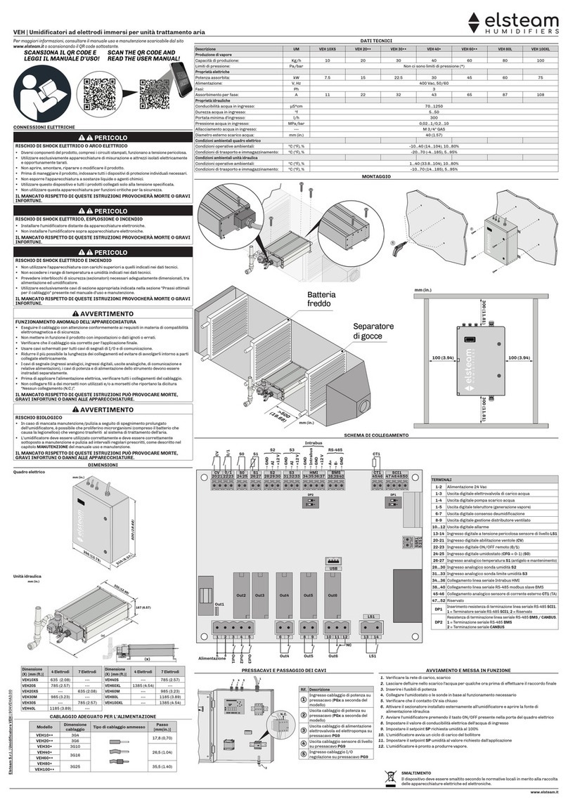
Elsteam VEH Series Installation and operating instructions

Elsteam
Elsteam VEH Series User manual
Elsteam
Elsteam MISTRAL User manual
Elsteam
Elsteam HPN Series Operating instructions
Elsteam
Elsteam ZEPHYR EHKT003M2 User manual

Elsteam
Elsteam AHU-VEH User manual

Elsteam
Elsteam REH4 Installation and operating instructions
Elsteam
Elsteam UH06-OEM Operating instructions
Elsteam
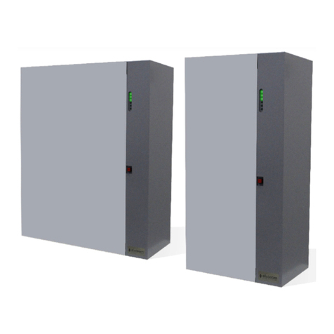
Elsteam KT User manual
Elsteam
Elsteam VEH20 Series User manual

