Elsteam HPN Series Operating instructions

HPN SERIES
HIGH PRESSURE PROPORTIONAL HUMIDIFIER
CENTRAL UNITS, SOLENOIDS CARDS AND
DISTRIBUTION RACK
USER, INSTALLATION AND MAINTENANCE GUIDE
Ver. 21.1.EN
MAIN UNIT
HPNCTRL
DISTRIBUTION RACK

HighPressure Humidifier - Constant Pressure
21.1.EN
2
Elsteam S.r.l - via E.fermi, 496 - 21042 Caronno Pertusella (va) - Tel.+39 02 9659890 - Fax +39 02 96457007
E-mail: info@elsteam.it - Web: http://www.elsteam.com
TOC
1PACKAGE CONTENT..................................................................................................................................................... 3
2SAFETY MEASURES..................................................................................................................................................... 3
2.1 GROUND CONNECTION ......................................................................................................................................................3
2.2 THERMO-HYGROMETRIC CONDITIONS OF THE INSTALLATION ..........................................................................................3
2.3 ELECTRICAL CONNECTIONS ..............................................................................................................................................3
2.4 HYDRAULIC CONNECTIONS ...............................................................................................................................................3
2.5 WASTE DISPOSAL .............................................................................................................................................................4
2.6 WARRANTY........................................................................................................................................................................4
3MANUFACTURER ......................................................................................................................................................... 4
4WORKING PRINCIPLE.................................................................................................................................................. 5
5CHARACTERISTICS ..................................................................................................................................................... 6
6INSTALLATION PRINCIPLES...................................................................................................................................... 7
7INSTALLATION.............................................................................................................................................................. 8
7.1 MAIN UNIT ........................................................................................................................................................................8
7.2 HPNCTRL ........................................................................................................................................................................8
7.3 DISTRIBUTION RACK .........................................................................................................................................................8
7.4 DROPLET SEPARATOR........................................................................................................................................................9
7.5 HYDRAULICS CONNECTIONS..............................................................................................................................................9
7.6 ELECTRICAL CONNECTIONS ........................................................................................................................................... 10
7.7 SETTING OF THE BYPASS CONTROL VALVE ..................................................................................................................... 11
8MAINTENANCE ...........................................................................................................................................................11
9ELECTRONIC CONTROLLER .....................................................................................................................................12
9.1 NORMAL OPERATION DISPLAY .................................................................................................................................... 12
9.2 ELECTRONIC CONTROLLER BASIC PROGRAMMING ........................................................................................................ 12
9.3 ELECTRONIC CONTROLLER ADVANCED PROGRAMMING (ONLY FOR MAINTENANCE/FITTER) ....................................... 14
10 ALARM MESSAGES................................................................................................................................................16
11 CONNECTIONS DIAGRAM ....................................................................................................................................17

HighPressure Humidifier - Constant Pressure
21.1.EN
3
Elsteam S.r.l - via E.fermi, 496 - 21042 Caronno Pertusella (va) - Tel.+39 02 9659890 - Fax +39 02 96457007
E-mail: info@elsteam.it - Web: http://www.elsteam.com
Please before using your equipment read this guide carefully, by noting all the precautions and safety
instructions reported in it. Keep your equipment in good operative conditions.
Familiarize with the working and security instructions related to the operation of your apparatus before
trying to make it function. Keep this guide and any other booklet provided with your apparatus to be able
to refer to them later.
1Package content
The High Pressure Humidifier package is composed of:
◊The high pressure humidifier central unit
◊This user guide
◊The high pressure pump user manual
◊The inverter user manual
◊A yellow cap for the pump oil to replace the red one (to be used only for transport)
2Safety measures
People who are not familiar with this type of apparatus or which did not read attentively this guide do not
have to be authorized to use the humidifier.
The humidifier is designed to be used on alternative 220Vac 50/60 Hz only. Do not try to connect it to a
different type of supply. Check that the sector supply voltage corresponds to that of the apparatus.
The humidifier must always be switched-off before any maintenance operations.
All operations of maintenance and repairs must be carried out by the manufacturer, his technical service
or any other qualified personnel to avoid any problem.
Do not cover any opening of the humidifier and do not insert objects in the openings
2.1 Ground Connection
The first operation of each installation is the correct ground connection for the equipment, following the
safety regulations of the state and at the time when the equipment is installed.
2.2 Thermo-hygrometric conditions of the installation
Check that the environmental conditions of the place where the installation is carried out are always
compatible with the requirements of the product as indicated in this manual. ELSTEAM products cannot
be installed exposed to weather conditions or frost, unless different conditions explicitly expressed in
countersigned documents.
2.3 Electrical Connections
ELSTEAM equipment must be connected to the power supply by carefully following the local regulations
and the specifications on the plates of the equipment.
In particular, it is mandatory that the power supply lines have a correct section and are equipped with a
standard disconnecting switch with differential safety (life-saving device) capable of protecting the user
not only against the device, but also against the power lines installed.
2.4 Hydraulic Connections
ELSTEAM equipment needs to be connected to the water supply. Supply water shall comply with
microbiological requirements of the German Drinking Water Ordinance (TrinkwV). Only ELSTEAM HPN
DEMI humidifier complies with VDI6022 certification when using reverse osmosis water (not in contact
with drinking-water mains). Should the unit be installed using normal water the installer must use a VDI
6022 non return valve to be still compliant.
It is necessary to strictly comply with the local actives regulations (for installation) and make sure that
any breakages or water leaks deriving from the installation or from the units itself cannot cause damage
to the environment or to third parties. Do not install the equipment on passageways or over dangerous or
susceptible objects and always provide special drainage systems that can evacuate any spilled water

HighPressure Humidifier - Constant Pressure
21.1.EN
4
Elsteam S.r.l - via E.fermi, 496 - 21042 Caronno Pertusella (va) - Tel.+39 02 9659890 - Fax +39 02 96457007
E-mail: info@elsteam.it - Web: http://www.elsteam.com
correctly.
2.5 Waste Disposal
Directive 2002/96 / EC of the European Parliament and the related national regulations impose the
obligation not to dispose of WEEE as urban civil waste, but to prepare a special collection for outdated
parts of the humidifier.
The purchaser has the right to return the disused humidifier to ELSTEAM srl in case of purchase of an
equivalent humidifier. ELSTEAM will arrange for its own disposal or through its appointees.
The disposal of electrical or electronic components in an abusive manner and not in compliance with
current regulations involves penalties.
2.6 Warranty
ELSTEAM Srl recognizes on its products the legal guarantees in force at the time of sale of the product.
Incorrect use and lack of maintenance entail the automatic forfeiture of any form of guarantee.
3Manufacturer
Manufacturer
ELSTEAM S.r.l.
Via ENRICO FERMI 496, 21042 CARONNO PERTUSELLA (VA) - ITALY
Contact
Tel.: (0039) 029659890
Fax: (0039) 0296457007
Email: info@elsteam.it
Web: www.elsteam.com

HighPressure Humidifier - Constant Pressure
21.1.EN
5
Elsteam S.r.l - via E.fermi, 496 - 21042 Caronno Pertusella (va) - Tel.+39 02 9659890 - Fax +39 02 96457007
E-mail: info@elsteam.it - Web: http://www.elsteam.com
4Working principle
The high-pressure humidifier performs an adiabatic humidification by atomization of softened water or
standard water at high pressure.
The system is composed by a central unit, a network control unit (HPNCTRL), a distribution rack and the
droplet separator (at the end of the humidification section, only for AHU installation).
The central unit maintains the pressure in the distribution network at a constant value (established based
on the model of nozzles used) as the number of active network sections varies.
The HPNCTRL, for proportional control of the distribution network, is installed in the environment to be
humidified or inside the AHU, managing section solenoids to make proportional production and
feed/drain solenoids to activate/empty the distribution network. One HPNCTRL must be installed for each
zone to control. The HPNCTRL card receive proportional or ON/OFF signal from the controlling system
and provide signals to the distribution networks solenoids and to the central unit. The HPNCRTL unit
opens the drain solenoid to empty the distribution rack when the control signal is 0.
The droplet eliminator is used to stop the droplets of water that are not completely evaporated before
they enter in the duct.

5Characteristics
TECHNICAL DATA
Code
HPN2L
DEMI
HPN3L
DEMI
HPN4L
DEMI
HPN5L
DEMI
HPN6L
DEMI
HPN7L
DEMI
HPN8L
DEMI
HPN9L
DEMI
HPN11L
DEMI
HPN14L
DEMI
SPRAY PRODUCTION
Max. Capacity
[l/h]
120
180
240
300
360
420
480
540
660
840
Max Pressure
[Mpa/bar
]
8/80 8/80 8/80 8/80 8/80 8/80 8/80 8/80 8/80 8/80
DISTRIBUTON RACK
Code
HPN2RA
CKxxx
HPN3RA
CKxxx
HPN4RA
CKxxx
HPN5RA
CKxxx
HPN6RA
CKxxx
HPN7RA
CKxxx
HPN8RA
CKxxx
HPN9RA
CKxxx
HPN11R
ACKxxx
HPN14R
ACKxxx
Max. Nozzles
(8l/h)
[n]
15
22
30
37
45
52
60
67
82
105
ELECTRICAL CONNECTIONS
Power [kW]
[kW]
1.5
1.5
1.5
1.5
1.5
1.5
2.2
2.2
4
4
Phases
[Vac, Hz]
1
3
Voltage
[n]
230V, 50/60Hz
400V, 50/60Hz
HYDRAULIC CONNECTIONS
Inlet water quality
---
Supply water shall comply with microbiological requirements of the German Drinking Water
Ordinance (TrinkwV). Supply water must be totally or partially demineralized by drinking water.
Should the unit be installed using normal water, the installer must use a VDI 6022 non-return
valve to be still compliant.
Inlet water
conductivity
μS*cm
0...100
Inlet water
hardness
°F
0...5
Input Pressure
[MPa/ba
r]
0,02...0,7 / 0,2...7
Water inlet
connection
---
M 3/4"GAS
Water drain
connection
---
M 1/4"GAS
HUMIDIFIER CONTROL
Control
---
Integrated on hydraulic module, remote on distribution rack
Control Signals
---
4…20mA (internal controller), 0-10V or ON-OFF (external signal)
MECHANICAL DATA
Dimensions
(WxHxD
[mm])
515x480x335 615x480x335
Weight (kg)
[kg]
50
IP protection
(Main Unit)
---
20
IP protection
(Distribution Rack)
---
40
Droplet Separator
HPNDROPxxx (optional)
CONFORMITY
CE
---
√
√
√
√
√
√
√
√
√
√
VDI6022
---
√
√
√
√
√
√
√
√
√
√

6Installation Principles
The figure below shows the basic working principle of the proportional humidifier. The output signal of
the humidistat (0-10V) controls the solenoids controlled card (for proportional working mode) as well as
the activation (threshold set at 1V) of the high pressure system.
The following figure shows instead an implementation of an installation with the network of nozzles split in
three sections with 33% and 66% thresholds.

HighPressure Humidifier - Constant Pressure
21.1.EN
8
Elsteam S.r.l - via E.fermi, 496 - 21042 Caronno Pertusella (va) - Tel.+39 02 9659890 - Fax +39 02 96457007
E-mail: info@elsteam.it - Web: http://www.elsteam.com
7Installation
7.1 Main unit
The cabinet of the humidification system must be installed in a ventilated and protected place. It must be
placed on a flat and stable surface. For a correct use and operation, as well as for an easy maintenance,
leave enough free space around the machine. To enable the correct ventilation of the unit is necessary to
ensure a free space of at least 20 cm close to the perforated panel for ventilation, which is located on the
right wall of the machine.
Do not place the machine in dangerous and/or explosive/inflammable places.
After installation the red cap of the oil tank, used for the transport, must be replaced by the yellow one,
used for normal working operation, provided with the system.
The access internal parts of the cabinet remove screws that secure the top and side panels.
7.2 HPNCTRL
The HPNCTRL card must be installed close to the distribution rack.
Electrical connections scheme is reported at the end of the document. Electrical connections to the high-
pressure solenoids (section, feed and drain) and main unit must be realised respecting local regulation.
The HPNCRTL card receives the regulation signal (ON/OFF or Proportional).
The HPNCRTL unit opens the drain solenoid to empty the solenoids lines when the control signal is 0.
7.3 Distribution rack
The case of the rack must be installed external to the AHU and fixed using dedicates holes. Hydraulic
connections to the rack (high pressure water input and drain) are respectively on the top and bottom of
the case. Three holes must be realised into the sandwich panel to let nozzles lines enter the AHU. When
mounting the nozzle lines a slope towards the case must be realised. This slope allows the lines to empty
totally when the system is off.
The rack must be installed in direct contact (thermally connected) to the HEATING COIL, to let the rack dry
when it is not used.
When shutting down the system for long periods, the humidifier must be switched-off before the
ventilation system, so to assure that the humidifier chamber is dry before complete shutdown.
During the first installation and all the operations of maintenance
please take care
of the
temperature sensor installed at the exit of high pressure pump.
Its damage may cause the breakage of the high pressure system.
Before first switch
-On replace the RED transport cap with the YELLOW cap having
a
built
-in dipstick provided.
The control signal mu
st be 0 in case of ventilation system failure or system shut off

HighPressure Humidifier - Constant Pressure
21.1.EN
9
Elsteam S.r.l - via E.fermi, 496 - 21042 Caronno Pertusella (va) - Tel.+39 02 9659890 - Fax +39 02 96457007
E-mail: info@elsteam.it - Web: http://www.elsteam.com
The nozzle lines must be connected in thermal contact with heating batteries in AHU, to be sure the
stainless steel pipes are always at drying temperature when the humidifiers is not working. This will dry
the empty network avoiding all possibilities of microbes growth and proliferation.
When installing the distribution rack (inside the AHU) the holes opened in the panel of the
must be closed using permanent elastic sealant that fulfils the requirement of the standard
VDI 6022-1.
7.4 Droplet separator
The “droplet separator” is made of stainless steel frame and glass fiber panel. It must be installed (only in
AHU) at minimum 150cm from the distribution network. It is care of the AHU manufacturer to make
stainless steel frame avoiding sharp edges and all corner than can allow dust deposits. Permanent elastic
sealant must be used in such a way to avoid dirt accumulation (make surfaces as smooth as possible).
The droplet separator must be easily removable to perform maintenance operation or unit replacing. As
the droplet eliminator is not intended to be cleaned, it must be replaced at end of its lifetime.
When installing the droplet separator (inside the AHU) the holes opened in the panel of the
must be closed using permanent elastic sealant that fulfils the requirement of the standard
VDI 6022-1.
7.5 Hydraulics connections
The connection between the pump and distribution network must be realized using pipes which supports
nominal pressure of 100bar (minimum), due to the high pressure (80 bar) in the network. It is preferable
to use stainless steel material.
Hydraulic connections are positioned on side panels of the cabinet. Input water connection is 3/4" and is
on the right side of the case; output is 3/8" and is on the left side.
A shut-off valve must be installed upstream (and nearby) humidifier for maintenance and
safety reasons operations.
Before installing the nozzles, it is mandatory to carry out a cleaning phase of the pipes
installed to
remove
all deposits in the pipes.

HighPressure Humidifier - Constant Pressure
21.1.EN
10
Elsteam S.r.l - via E.fermi, 496 - 21042 Caronno Pertusella (va) - Tel.+39 02 9659890 - Fax +39 02 96457007
E-mail: info@elsteam.it - Web: http://www.elsteam.com
Only HPNxxDEMI models complies with VDI6022 standards.
The High Pressure Humidifier can work with standard or demineralised water. Different pumps materials
(STAINLESS STEEL for reverse osmosis water, BRASS for normal tap water) are used in the two versions.
The water pressure at the input must not be lower than 1bar.
For proper operation in according to VDI standards, stagnation of water in supply lines shall be avoided.
When shutting down the system for long periods particular care must be taken to empty supply lines or
keep active water treatment systems.
7.6 Electrical Connections
Before starting installation:
◊Check that the supply voltage and the frequency correspond to those indicated on the rating plate.
◊The dimensions of the supply cable must suit the machine absorption and comply with the current
regulations.
◊Put the cable in the relevant cable passage hole and then tighten.
Connectors for electrical connections are located inside the upper part of the cabinet (to access it you
need to remove the upper panel of the cabinet). It is recommended to isolate the machine from the mains
before each intervention and in any case in absence of protective covers (dangerously live electrical
parts are present inside).
The power supply line must be connected to the input of the circuit breaker, for the ground connection
there is a special yellow-green terminal, the hole for the cables is located on the rear of the cabinet.
Controls and alarm signals are found in the card connectors (to access it, remove the upper panel of the
cabinet) and the opening for these cables is also in the rear of the cabinet.
Controller Terminal Block
All operations of electrical installation MUST be performed by qualified personnel (
eg
electrician or staff with appropriate training) only.
The customer is responsible for the use of qualified personnel.
Prior to carrying out any inspection or service on the machine, it is necessary to
disconnect it from the main electrical supply. Make sure, that nobody can reconnect it
during the technical service.
Every installed electrical and electronic equipment or basic structure must be
earthed.

HighPressure Humidifier - Constant Pressure
21.1.EN
11
Elsteam S.r.l - via E.fermi, 496 - 21042 Caronno Pertusella (va) - Tel.+39 02 9659890 - Fax +39 02 96457007
E-mail: info@elsteam.it - Web: http://www.elsteam.com
N°
Name
Description
3
ALARM
Alarm
Normally opened contact. (Max. 2A, 230V).
4
ALARM
5
REQ
NOT USED
6
REQ
7
0 V
Ground reference voltage (0V)
8
REG
Input Control Signal (0-10V)
9
V+
Positive Reference Voltage (12V)
10
RTH
NOT USED
11
ACOUT
NOT USED
All connections between the controller and the solenoid card are made at the factory. The user must
connect the output signal of the humidistat to the terminals 7 (-) and 8 (+) taking care of polarities.
For ON/OFF driving connect the wires to terminals 8 and 9.
The HPNCTRL card proportional or ON/OFF control signal must be shut off in case of ventilation failure or
AHU shutdown to stop mist entering into the AHU without airflow.
7.7 Setting of the bypass control valve
The high-pressure system has a bypass valve for regulating the output pressure. At first power on is
necessary to control the adjustment of this valve.
In the case of a successful installation, you can adjust the maximum pressure (turning clockwise the
valve). It is advisable to adjust the output pressure up to a pressure of about 80 bar.
It's also possible to reduce the output pressure in case “Etb” message is displayed on the inverter display
(lower limit for output pressure is 30bar).
8Maintenance
A high pressure humidification system requires some periodic maintenance operations for its proper
operation:
•Change the oil pump every 500 hours, as indicated on the attached manual pump, closing
the inlet water and removing the top caps and bottom as shown in figure
•Periodically check the wear of the nozzles. The nozzles worn may cause the blocking of the
machine due to an excessive reduction of output pressure
•Check periodically pump oil level:

HighPressure Humidifier - Constant Pressure
21.1.EN
12
Elsteam S.r.l - via E.fermi, 496 - 21042 Caronno Pertusella (va) - Tel.+39 02 9659890 - Fax +39 02 96457007
E-mail: info@elsteam.it - Web: http://www.elsteam.com
If oil level is not within zone, add or remove oil in the tank. Check for oil leaks.
NOTE
The high pressure humidifier presents a thermal protection for the pump system. Be extremely careful
not to damage the temperature sensor mounted on the pump.
9Electronic Controller
All operation of the high pressure humidifier are managed by a micro controller based board. All
information is provided through a 16 characters by 2 lines display. Its main functions are:
•Switch On/Off of the system
•Check the real working time of the system
•Provide information about replacement of spare parts and pump oil.
•Display information about parameters
•Provide different alarms
9.1 Normal operation DISPLAY
During normal operation the electronic controller display show on the first line main parameters of the
system:
: System State:
•“u” : indicates proper operation of the system
•“!” : indicates temperature protection intervention
•“x” : indicates that no request is present
: Pump temperature indication bar
: Minimum operating time of the pump. At startup/shutdown of the pump “t” character is displayed.
During the inhibit time (factory setting: 60 s). During this period system shutdown or startup is
inhibited.
“W” character indicates that input water solenoid is opened
“i” character indicates that input water flow is sufficient for system operation. If “i” is not shown, there is
a problem in input water flow or pressure.
The second line indicates the pressure value in the nozzles network.
9.2 Electronic controller basic programming
To enter the basic programming mode press the SET button for 2 seconds, until the following message is
displayed:
During the first programming of the controller is advisable to disconnect the control
signals (Pin 8 of the terminal) to avoid that the humidifier is put into operation.
H P NT Wi
Pou t = x x . x b a r

HighPressure Humidifier - Constant Pressure
21.1.EN
13
Elsteam S.r.l - via E.fermi, 496 - 21042 Caronno Pertusella (va) - Tel.+39 02 9659890 - Fax +39 02 96457007
E-mail: info@elsteam.it - Web: http://www.elsteam.com
Humidify System
-- Enabled --
To modify the value of a field or to move between fields use + and - buttons. During value changing, the
value of the field blinks.
To end the programming of a field press the OK button to set the new value, CANC button to cancel
modification or OK , SET or CANC for more than 3 seconds to exit programming phase.
Programming phase automatically ends without current parameter update if no button is pressed for 3
seconds.
Note: To save updated values do not abandon programming pressing CANC button.

HighPressure Humidifier - Constant Pressure
21.1.EN
14
Elsteam S.r.l - via E.fermi, 496 - 21042 Caronno Pertusella (va) - Tel.+39 02 9659890 - Fax +39 02 96457007
E-mail: info@elsteam.it - Web: http://www.elsteam.com
Basic menu programming fields are:
Display
Description
Humidify System
Enable or disable the humidifier
"
Enabled
", System on
"Disabled", System off
Life Time
Display the effective working time of the system
This field is read only. Cannot be modified by the user
Change Oil Timer
Display the remaining time before pump oil change
c. Cannot be modified by the user
9.2.1 Counter of the remaining time before pump oil change
The high pressure pump requires changing the oil every 500 hours of operation (the first oil change
should be made after 50 hours of operation). Use SAE 15W40 mineral oil. The quantity of oil needed
depends on the pump flow. Please refer to the pump system manual for details.
The controller counts the time remaining for the next oil change. At the end of that period the message
"ChangeOil xxxxxh" is displayed to inform user that oil must be changed. After this message there is still a
period of 50 hours before the controller BLOCKS the system.
If oil is changed before scheduled time (before the controller blocks the system), the oil counter must be
reset by pressing SET and OK buttons. When the message “Pump Oil has been changed” is displayed,
press OK button to confirm and reset the counter. By pressing CANC button the counter is not reset and
the system will stop at counter expiration.
At expiration of extended period the system will stop working and following message will be displayed
“System Failure - Change the Oil of the Pump”.
Once the oil is changed do not forget to reset the oil counter by pressing OK button. When the message
“Pump Oil has been changed” is displayed, press OK button to confirm and reset the counter. By pressing
CANC button the counter is not reset and the system will remain blocked.
9.2.2 Display of the remaining time
During normal working operation the user can display remaining time before oil change pressing -
button.
9.2.3 LCD Contrast change
If necessary the user can modify the value of the display contrast pressing CANC button and one of +
or
- button.
9.2.4 Display of Firmware version
User can display the installed firmware version pressing + and - buttons.
9.3 Electronic controller advanced programming
(only for maintenance/fitter)
Advanced programming mode allows maintenance people and fitters to modify additional parameters
depending on the working conditions of the HPN system.
To enter the advanced programming mode press SET and + buttons for 2 seconds, until the following
message is displayed:
Humidify System
-- Enabled --

HighPressure Humidifier - Constant Pressure
21.1.EN
15
Elsteam S.r.l - via E.fermi, 496 - 21042 Caronno Pertusella (va) - Tel.+39 02 9659890 - Fax +39 02 96457007
E-mail: info@elsteam.it - Web: http://www.elsteam.com
Advanced menu programming fields are:
Display
Description
Humidify System
Enable or disable the humidifier
"
Enabled
", System on
"Disabled", System off
Life Time
Display the effective working time of the system
This field is read only. Cannot be modified by the user
Change Oil Timer
Display the remaining time before pump oil change
This field is read only. Cannot be modified by the user
Pump Rate
Set the system flow rate
Indicates the nozzle system flow rate, not the pump one. In the
current version must be set to minimum value. Will be used to
provide information about real water consumption.
Minimum External
Signal xxx/100%
Minimum value of external controller signal (only proportional
controller)
This value is expressed in percentage of 10V. In case of noise on the
external signal line, parameter value can be increased. (Default
value 10%)
Output Pressure
Timeout= xxx sec
Max time to reach standard pressure in the nozzles network
If within this period from system start, pressure in the nozzles pipe
has not reached the default value, the embedded controller stops
the system providing the following error message “
Low Output
Pressure
”.
To restart the system after failure solution, press
OK
. (Default value
60 sec)
Minimum On/Off
Time = 000 sec
Minimum System On/Off time
To avoid frequent stop and start of the pump (that can damage it) a
minimum period is set by electronic controller. During this period
switch on and off of the system is inhibited unless the circuit
breaker is used (NOT RECOMMENDED).
In cases of frequent starting and stopping of the pump, increase the
value. (Default Value : 60 sec)
Std Pressure
xxx bar
Standard value of pressure
This parameter allows the fitter to modify the default value of the
pressure in the nozzles network. (Default Value: 80bar)
4..20mA Coeff. P
P= xx.xbar)yyyyy
Pressure transducer Coefficient
On the second line of the LCD display the pressure value and probe
coefficient are showed.
(Default Value: 8850)
To
confirm the changes made to a field, use SET or OK. To exit the
advanced
programming mode,
press SET or OK. To store the changes
in the FLASH memory
of the microcontroller
press SET or OK for more than 3 seconds. Using the
CANC
key
changes to a field will not be stored in FLASH and new values will be valid
until
the next
switch off the humidifier (using circuit breaker).

HighPressure Humidifier - Constant Pressure
21.1.EN
16
Elsteam S.r.l - via E.fermi, 496 - 21042 Caronno Pertusella (va) - Tel.+39 02 9659890 - Fax +39 02 96457007
E-mail: info@elsteam.it - Web: http://www.elsteam.com
10Alarm Messages
To remove alarm conditio0n and restart the system press OK key.
Message
Insufficient Water
Cause
Lack of input water
Inverter security error
Possible Solution
Check input water flow.
Check inverter display for error messages. If “Etb
” message is displayed the output
pressure security pressure switch stopped the system. Check the output bypass valve.
Turn it counterclockwise to reduce output pressure.
Remove one nozzle from the network and try the system. Press OK key to remove
alarm condition and restart the system.
If the alarm condition stops:
•Replace nozzle and restart the system
If the system is still in alarm, please contact ELSTEAM or your distributor for input flow
meter replacement part.
Message
Check Load Valve Driver
Cause
Driving of input water solenoid failure
Possible Solution
If “W” character is displayed in the first line, check solenoid connections and voltage
(12V). Press OK key to remove alarm condition and restart the system.
If the system is still in alarm, please contact ELSTEAM or your distributor for part
replacement.
Message
NTC failure
Cause
The pump temperature probe is damaged.
Possible Solution
Contact ELSTEAM or your distributor for part replacement.
Message
Low Output Pressure
Cause
The pressure in the nozzle pipe cannot reach the default value within the set period.
Possible Solution
Check distribution network and output connection pipe for draining.
Check the output bypass valve. To increase the output
pressure turn clockwise the
valve.
Message
Pump Overheating, check atomizers
Cause
Pump temperature high.
Possible Solution
Check the output bypass valve. Turn it counterclockwise to reduce output pressure.
CAUTION
The controller stores the status of the humidifier in a FLASH memory.
Turning the system off and on to remove alarm conditions has no effect

HighPressure Humidifier - Constant Pressure
21.1.EN
17
Elsteam S.r.l - via E.fermi, 496 - 21042 Caronno Pertusella (va) - Tel.+39 02 9659890 - Fax +39 02 96457007
E-mail: info@elsteam.it - Web: http://www.elsteam.com
Connections Diagram
Other manuals for HPN Series
1
This manual suits for next models
11
Table of contents
Other Elsteam Humidifier manuals
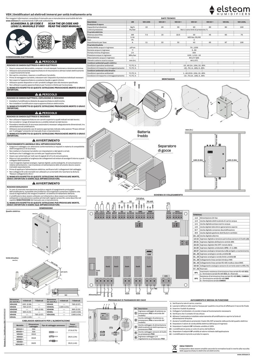
Elsteam
Elsteam VEH20 Series User manual
Elsteam
Elsteam VEH Series User manual

Elsteam
Elsteam VEH Series Installation and operating instructions
Elsteam
Elsteam UH06-OEM Operating instructions

Elsteam
Elsteam REH4 Installation and operating instructions
Elsteam
Elsteam KT Series User manual
Elsteam
Elsteam MISTRAL User manual
Elsteam
Elsteam ZEPHYR EHKT003M2 User manual
Elsteam
Elsteam KT User manual

Elsteam
Elsteam AHU-VEH User manual


