Elsteam VEH20 Series User manual
Elsteam S.r.l. | Umidificatore VEH | 904VEHA3.00
www.elsteam.it
VEH | Umidificatori ad elettrodi immersi per unità trattamento aria
Per maggiori informazioni, consultare il manuale uso e manutenzione scaricabile dal sito
www.elsteam.it o scansionando il QR code sottostante.
SCANSIONA IL QR CODE E
LEGGI IL MANUALE D’USO!
SCAN THE QR CODE AND
READ THE USER MANUAL!
CONNESSIONI ELETTRICHE
PERICOLO
RISCHIO DI SHOCK ELETTRICO O ARCO ELETTRICO
• Diversi componenti del prodotto, compresi i circuiti stampati, funzionano a tensione pericolosa.
• Utilizzare esclusivamente apparecchiature di misurazione e attrezzi isolati elettricamente
e opportunamente tarati.
• Non aprire, smontare, riparare o modificare il prodotto.
• Prima di maneggiare il prodotto, indossare tutti i dispositivi di protezione individuali necessari.
• Non esporre l'apparecchiatura a sostanze liquide o agenti chimici.
• Utilizzare questo dispositivo e tutti i prodotti collegati solo alla tensione specificata.
• Non utilizzare questa apparecchiatura per funzioni critiche per la sicurezza.
IL MANCATO RISPETTO DI QUESTE ISTRUZIONI PROVOCHERÀ MORTE O GRAVI
INFORTUNI.
PERICOLO
RISCHIO DI SHOCK ELETTRICO, ESPLOSIONE O INCENDIO
• Installare l'umidificatore distante da apparecchiature elettroniche.
• Non installare l'umidificatore sopra apparecchiature elettroniche.
IL MANCATO RISPETTO DI QUESTE ISTRUZIONI PROVOCHERÀ MORTE O GRAVI
INFORTUNI.
PERICOLO
RISCHIO DI SHOCK ELETTRICO E INCENDIO
• Non utilizzare l'apparecchiatura con carichi superiori a quelli indicati nei dati tecnici.
• Non eccedere i range di temperatura e umidità indicati nei dati tecnici.
• Prevedere interblocchi di sicurezza (sezionatori) necessari adeguatamente dimensionati, tra
alimentazione ed umidificatore.
• Utilizzare esclusivamente cavi di sezione appropriata indicata nella sezione "Prassi ottimali
per il cablaggio" presente nel manuale d'uso e manutenzione.
IL MANCATO RISPETTO DI QUESTE ISTRUZIONI PROVOCHERÀ MORTE O GRAVI
INFORTUNI.
AVVERTIMENTO
FUNZIONAMENTO ANOMALO DELL'APPARECCHIATURA
• Eseguire il cablaggio con attenzione conformemente ai requisiti in materia di compatibilità
elettromagnetica e di sicurezza.
• Non mettere in funzione il prodotto con impostazioni o dati ignoti o errati.
• Verificare che il cablaggio sia corretto per l'applicazione finale.
• Usare cavi schermati per tutti cavi di segnali di I/O e di comunicazione.
• Ridurre il più possibile la lunghezza dei collegamenti ed evitare di avvolgerli intorno a parti
collegate elettricamente.
• I cavi di segnale (ingressi analogici, ingressi digitali, uscite analogiche, di comunicazione e
relative alimentazioni), i cavi di potenza e di alimentazione dello strumento devono essere
instradati separatamente.
• Prima di applicare l’alimentazione elettrica, verificare tutti i collegamenti del cablaggio.
• Non collegare fili a dei morsetti non utilizzati e/o a morsetti che riportano la dicitura
“Nessun collegamento (N.C.)”.
IL MANCATO RISPETTO DI QUESTE ISTRUZIONI PUÒ PROVOCARE MORTE,
GRAVI INFORTUNI O DANNI ALLE APPARECCHIATURE.
AVVERTIMENTO
RISCHIO BIOLOGICO
• In caso di mancata manutenzione/pulizia a seguito di spegnimento prolungato
dell'umidificatore, è possibile che proliferino microrganismi (compreso il batterio che
causa la legionellosi) che vengono trasferiti al sistema di trattamento dell'aria.
• L'umidificatore deve essere utilizzato correttamente e deve essere correttamente
sottoposto a manutenzione e pulizia ad intervalli regolari prescritti, come descritto nel
capitolo MANUTENZIONE del manuale uso e manutenzione.
IL MANCATO RISPETTO DI QUESTE ISTRUZIONI PUÒ PROVOCARE MORTE,
GRAVI INFORTUNI O DANNI ALLE APPARECCHIATURE.
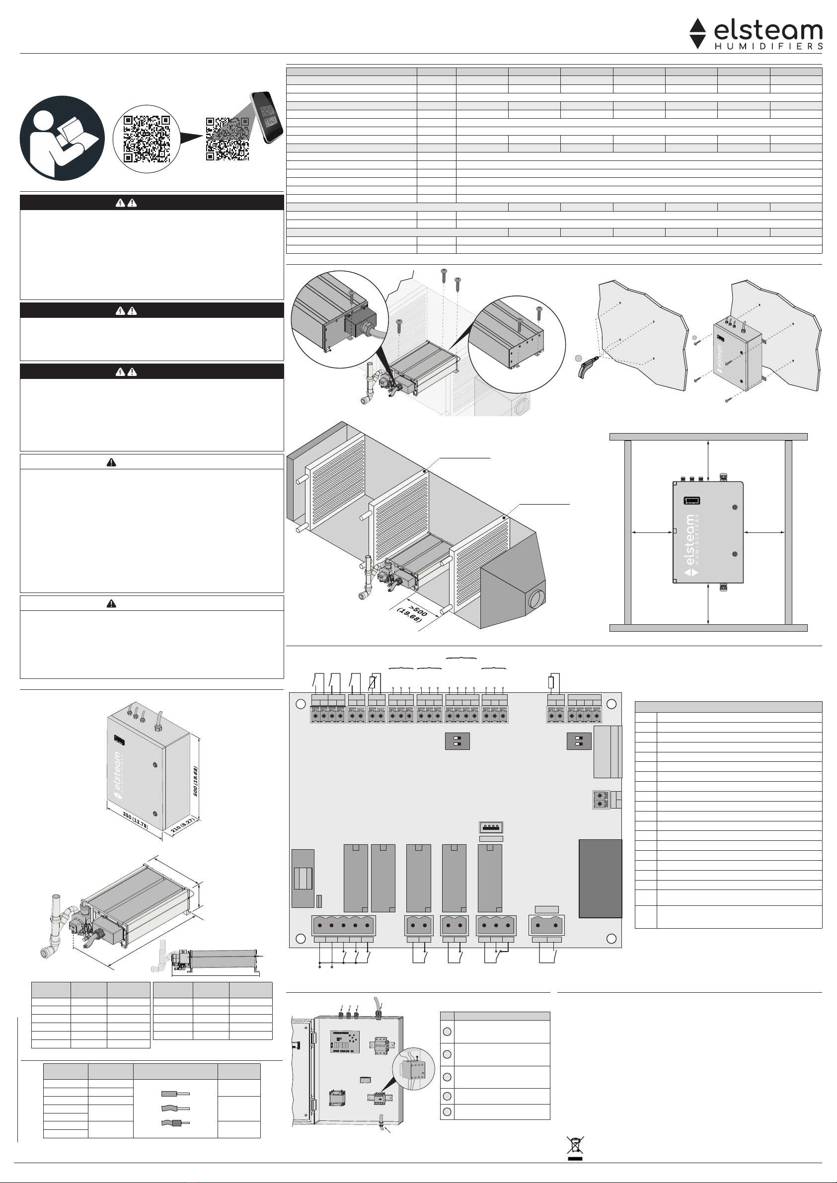
DIMENSIONI
Quadro elettrico
mm (in.)
Unità idraulica
(x)
167 (6.57)
330 (12.99)
mm (in.)
(x)
Dimensione
(X) [mm (ft.)] 4 Elettrodi 7 Elettrodi Dimensione
(X) [mm (ft.)] 4 Elettrodi 7 Elettrodi
VEH10XS
635 (2.08) ---
VEH40S
--- 785 (2.57)
VEH20S
785 (2.57) ---
VEH60XL
1385 (4.54) ---
VEH20XS
--- 635 (2.08)
VEH60M
--- 985 (3.23)
VEH30M
985 (3.23) ---
VEH80L
--- 1185 (3.89)
VEH30S
--- 785 (2.57)
VEH100XL
--- 1385 (4.54)
VEH40L
1185 (3.89) ---
CABLAGGIO ADEGUATO PER L'ALIMENTAZIONE
Modello Dimensione
cablaggio Tipo di cablaggio ammesso Passo
[mm(in.)]
VEH10•• 3G4 17,8 (0,70)
VEH20•• 3G6
VEH30• 3G10
26,5 (1.04)VEH40• 3G16
VEH60••
VEH80• 3G25 35,5 (1.40)
VEH100••
DATI TECNICI
Descrizione UM VEH 10XS VEH 20••
VEH 30
••
VEH 40
•
VEH 60
••
VEH 80L VEH 100XL
Produzione di vapore
Capacità di produzione: Kg/h 10 20 30 40 60 80 100
Limiti di pressione: Pa/bar Non ci sono limiti di pressione (*)
Proprietà elettriche
Potenza assorbita: kW 7.5 15 22.5 30 45 60 75
Alimentazione: V, Hz 400 Vac, 50/60
Fasi: Ph 3
Assorbimento per fase: A11 22 32 43 65 87 108
Proprietà idrauliche
Conducibilità acqua in ingresso: μS*cm 70…1250
Durezza acqua in ingresso: °f 5...50
Portata minima d'ingresso: l/h 300
Pressione acqua in ingresso:
MPa/bar
0,02...1/0,2...10
Allacciamento acqua in ingresso: --- M 3/4" GAS
Diametro esterno scarico acqua
:mm (in.) 40 (1.57)
Condizioni ambientali quadro elettrico
Condizioni operative ambientali: °C (°F), % -10...40 (14...104), 10...80%
Condizioni di trasporto e immagazzinamento: °C (°F), % -20...70 (-4...185), 5...95%
Condizioni ambientali unità idraulica
Condizioni operative ambientali: °C (°F), % 1...40 (33.8...104), 10...80%
Condizioni di trasporto e immagazzinamento: °C (°F), % -10...70 (14...185), 5...95%
MONTAGGIO
SCHEMA DI COLLEGAMENTO
USB
LS1
Out1
Out1
Out2
Out3
Out4 Out5 Out6
NC
LS1
Out2 Out3 Out4 Out5 Out6
1 2 3 4 5 6 7 8 9 10 11 12 13 14
20
CV S0 S1 S2 S3 HMI BMS CT1 SCI1
0/1
21 22 23 24 25 26 27 28 29 30 31 32 33 34 35 36 37 38 39 40 45 46 47 48
DP1
ON
1 2
49 50
5152
SSR1
DP2
ON
1 2
Alimentazione
GND
AI
+12 V
GND
GND
B-
A+
AI
+12 V
GND
GND
Intrabus
+12 V
CV
0/1
S0 S1 CT1
S2 S3 RS-485
Intrabus
TERMINALI
1-2 Alimentazione 24 Vac
1-3 Uscita digitale elettrovalvola di carico acqua
1-4 Uscita digitale pompa scarico acqua
1-5
Uscita digitale teleruttore (generazione vapore)
6-7 Uscita digitale consenso deumidificazione
8-9 Uscita digitale gestione distributore ventilato
10...12 Uscita digitale allarme
13-14
Ingresso digitale a tensione pericolosa sensore di livello LS1
20-21 Ingresso digitale abilitazione ventole (CV)
22-23 Ingresso digitale ON/OFF remoto (0/1)
24-25 Ingresso digitale umidostato (CFG = 0-1) (S0)
26-27
Ingresso analogico temperatura S1 (antigelo e mantenimento)
28...30 Ingresso analogico sonda umidità S2
31...33 Ingresso analogico sonda limite umidità S3
34...36
Collegamento linea seriale Intrabus HMI
38...40
Collegamento linea seriale RS-485 modbus slave BMS
45-46
Collegamento analogico sensore di corrente esterno CT1 (TA)
47...52
Riservato
DP1
Inserimento resistenza di terminazione linea seriale RS-485 SCI1.
1 = Terminatore seriale RS-485 SCI1; 2= Riservato
DP2
Resistenza di terminazione linea seriale RS-485 BMS / CANBUS.
1 = Terminazione seriale RS-485 BMS
2= Terminazione seriale CANBUS
PRESSACAVI E PASSAGGIO DEI CAVI
2
34 5 1
N.C.
Rif. Descrizione
1Ingresso cablaggio di potenza su
pressacavo (PGx a seconda del
modello)
2Uscita cablaggio di potenza su
pressacavo (PGx a seconda del
modello)
3Uscita cablaggio di alimentazione
elettrovalvola ed elettropompa su
pressacavo PG9
4Uscita cablaggio sensore di livello
su pressacavo PG9
5Ingresso cablaggio I/O
regolazione su pressacavo PG9
AVVIAMENTO E MESSA IN FUNZIONE
1. Verificare la rete di carico, scarico
2. Lasciare defluire nello scarico l'acqua per qualche ora prima di eettuare il raccordo finale
3. Inserire i fusibili di potenza
4. Collegare l'umidostato o le sonde in base al funzionamento necessario
5. Verificare che il contatto CV sia chiuso
6. Attivare il sezionatore installato esternamente all'umidificatore e aprire la fonte di
alimentazione idraulica
7. Avviare l'umidificatore premendo il tasto ON/OFF presente nella porta del quadro elettrico
8. Impostare il valore di conducibilità elettrica dell'acqua di ingresso
9. Impostare il setpoint SP richiesta umidità al 100%
10. L'umidificatore avvia un ciclo di carico del bollitore
11. Impostare il setpoint SP umidità al valore richiesto dall'applicazione
12. L'umidificatore è pronto a produrre vapore.
SMALTIMENTO
Il dispositivo deve essere smaltito secondo le normative locali in merito alla raccolta
delle apparecchiature elettriche ed elettroniche.
1
2
Batteria
freddo
mm (in.)
Separatore
di gocce
100 (3.94) 100 (3.94)
mm (in.)
300 (11.81) 300 (11.81)

www.elsteam.it
Elsteam S.r.l. | VEH Humidifier | 904VEHA3.00
VEH | Immersed electrode humidifiers for air handling units (AHU)
Disposal
The device must be disposed of in accordance with local regulations regarding the
collection of electrical and electronic appliances.
For further information, consult the operating and maintenance manual downloadable from
the website www.eslteam.it or scan the QR CODE.
SCANSIONA IL QR CODE E
LEGGI IL MANUALE D’USO!
SCAN THE QR CODE AND
READ THE USER MANUAL!
ELECTRICAL WIRING
DANGER
RISK OF ELECTRIC SHOCK, EXPLOSION OR ELECTRIC ARC
• Various product components, including the printed circuits, run at hazardous voltage levels.
• Only use electrically insulated and suitably calibrated measuring devices and equipment.
• Do not open, disassemble, repair or modify the product.
• Before handling the product, make sure you are wearing all the necessary personal protective
equipment (PPE).
• Do not expose the equipment to liquids or chemicals.
• Use this device and all parts connected to it at the specified voltage only.
• Do not use this equipment for critical safety functions.
FAILURE TO FOLLOW THESE INSTRUCTIONS WILL RESULT IN DEATH OR
SERIOUS INJURY.
DANGER
RISK OF ELECTRIC SHOCK, EXPLOSION OR FIRE
• Install the humidifier away from electronic equipment.
• Do not install the humidifier above electronic equipment.
FAILURE TO FOLLOW THESE INSTRUCTIONS WILL RESULT IN DEATH OR
SERIOUS INJURY.
DANGER
RISK OF ELECTRIC SHOCK AND FIRE
• Do not use the device with loads greater than those indicated in the technical data section.
• Do not exceed the temperature and humidity ranges indicated in the technical data section.
• Provide safety interlocks (isolators) of a suitable size between the power supply and the humidifier.
• Only use cables with a suitable cross-section as indicated in the “Wiring best practices” section of the
operating and maintenance manual.
FAILURE TO FOLLOW THESE INSTRUCTIONS WILL RESULT IN DEATH OR
SERIOUS INJURY.
WARNING
MALFUNCTIONING OF THE EQUIPMENT
• Perform the wiring carefully, in compliance with electromagnetic compatibility and safety
requirements.
• Do not operate the product with unknown or incorrect settings or data.
• Make sure the wiring is correct for the final application.
• Use shielded cables for all I/O signal and communication cables.
• Minimise the length of the connections as much as possible and avoid winding the cables
around electrically connected parts.
• The signal cables (analogue and digital inputs, communication and corresponding power
supplies), power cables and power supply cables for the device must be routed separately.
• Before applying the power supply, check all the wiring connections.
• Do not connect wires to unused terminals and/or to terminals labelled “No connection “(N.C.)”.
FAILURE TO FOLLOW THESE INSTRUCTIONS CAN RESULT IN DEATH, SERIOUS
INJURY, OR EQUIPMENT DAMAGE.
WARNING
BIOLOGICAL RISK
• In the event of inadequate use and/or poor maintenance it is possible that microorganisms
(including the bacterium that causes Legionellosis) may proliferate and be transferred into
the air treatment system.
• The humidifier must be used properly and be maintained and cleaned properly at
prescribed intervals, as described in chapter MAINTENANCE in the manual of operating
and maintenance.
FAILURE TO FOLLOW THESE INSTRUCTIONS CAN RESULT IN DEATH, SERIOUS
INJURY, OR EQUIPMENT DAMAGE.
DIMENSIONS
Electrical panel
mm (in.)
Hydraulic unit
(x)
167 (6.57)
330 (12.99)
mm (in.)
(x)
Dimensions
(X) [mm (ft.)] 4 Electrodes 7 Electrodes Dimensions
(X) [mm (ft.)] 4 Electrodes 7 Electrodes
VEH10XS
635 (2.08) ---
VEH40S
--- 785 (2.57)
VEH20S
785 (2.57) ---
VEH60XL
1385 (4.54) ---
VEH20XS
--- 635 (2.08)
VEH60M
--- 985 (3.23)
VEH30M
985 (3.23) ---
VEH80L
--- 1185 (3.89)
VEH30S
--- 785 (2.57)
VEH100XL
--- 1385 (4.54)
VEH40L
1185 (3.89) ---
SUITABLE WIRING FOR THE POWER SUPPLY
Models Wiring size Permissible wiring type Pitch
[mm(in.)]
VEH10•• 3G4 17,8 (0,70)
VEH20•• 3G6
VEH30• 3G10
26,5 (1.04)VEH40• 3G16
VEH60••
VEH80• 3G25 35,5 (1.40)
VEH100••
TECHNICAL SPECIFICATIONS
Description MU VEH 10XS VEH 20••
VEH 30
••
VEH 40
•
VEH 60
••
VEH 80L VEH 100XL
Steam production
Production capacity: kg/h 10 20 30 40 60 80 100
Pressure limits: Pa/bar There are no pressure limits (*)
Electrical properties
Power absorbed: kW 7.5 15 22.5 30 45 60 75
Power supply: V, Hz 400 Vac, 50/60
Phases: Ph 3
Absorption per phase: A11 22 32 43 65 87 108
Water properties
Supply water conductivity: μS*cm 70…1250
Supply water hardness: °f 5...50
Minimum inlet flow rate: l/h 300
Supply water pressure:
MPa/bar
0.02...1/0.2...10
Supply water connection: --- M 3/4" GAS
Water drain outside diameter
:mm (in.) 40 (1.57)
Electrical panel ambient conditions
Ambient operating conditions: °C (°F), % -10...40 (14...104), 10...80%
Transportation and storage conditions: °C (°F), % -20...70 (-4...185), 5...95%
Hydraulic unit ambient conditions
Ambient operating conditions: °C (°F), % 1...40 (33.8...104), 10...80%
Transportation and storage conditions: °C (°F), % -10...70 (14...185), 5...95%
MOUNTING
WIRING DIAGRAM
USB
LS1
Out1
Out1
Out2
Out3
Out4 Out5 Out6
NC
LS1
Out2 Out3 Out4 Out5 Out6
1 2 3 4 5 6 7 8 9 10 11 12 13 14
20
CV S0 S1 S2 S3 HMI BMS CT1 SCI1
0/1
21 22 23 24 25 26 27 28 29 30 31 32 33 34 35 36 37 38 39 40 45 46 47 48
DP1
ON
1 2
49 50
5152
SSR1
DP2
ON
1 2
Power supply
GND
AI
+12 V
GND
GND
B-
A+
AI
+12 V
GND
GND
Intrabus
+12 V
CV
0/1
S0 S1 CT1
S2 S3 RS-485
Intrabus
TERMINALS
1-2 24 Vac power supply
1-3 Digital output: water outlet solenoid valve
1-4 Digital output: water outlet pump
1-5
Digital output: contactor (steam generation)
6-7 Digital output: dehumidification enable
8-9 Digital output: ventilated distributor control
10...12 Digital output: alarm
13-14
Hazardous voltage digital input: level sensor LS1
20-21 Digital input: fan enable (CV)
22-23 Digital input: remote ON/OFF (0/1)
24-25 Digital input: humidistat (CFG = 0-1) (S0)
26-27
S1 analogue input: temperature (anti-freezing and hold)
28...30 S2 analogue input: humidity sensor
31...33 S3 analogue input: humidity limit sensor
34...36
Serial line connection: HMI Intrabus
38...40
Serial line connection: RS-485 modbus for BMS slave
45-46
Analogue connection: external current sensor CT1 (TA)
47...52
Reserved
DP1
Activate termination resistor on SCI1 RS-485 serial line.
1 = SCI1 RS-485 serial termination; 2= Reserved
DP2
Termination resistor on BMS / CANBUS RS-485.
1 = BMS RS-485 serial termination
2 = CANBUS serial termination
CABLE GLANDS AND CABLE ROUTING
2
34 5 1
N.C.
Rif. Descrizione
1Power cable entry on cable gland
(PGx depending on model)
2Power cable exit on cable gland
(PGx depending on model)
3Solenoid valve and electric pump
power cable exit on cable gland
PG9
4Level sensor wiring exit on cable
gland PG9
5I/O regulation wiring entry on
cable gland PG9
POWERUP AND STARTUP
1. Check the filling and drain network
2. Let the water drain for a few hours before making the final connection
3. Fit the power fuses
4. Connect the humidistat or the probe in accordance with the required operation
5. Check that the CV contact is closed
6. Activate the isolator installed outside the humidifier and open the water supply source
7. Press the ON/OFF key on the electric panel door to start the humidifier
8. Set the electrical conductivity of the incoming water
9. Set the humidity setpoint SP to 100%
10. The humidifier will start a boiler filling cycle
11. Set the humidity setpoint SP to the value required for the application
12. The humidifier is ready to produce steam.
1
2
100 (3.94) 100 (3.94)
mm (in.)
300 (11.81) 300 (11.81)
mm (in.)
Cooling
coil
Droplet
separator
This manual suits for next models
6
Table of contents
Languages:
Other Elsteam Humidifier manuals

Elsteam
Elsteam UH06-OEM Operating instructions

Elsteam
Elsteam HPN Series Installation manual

Elsteam
Elsteam VEH Series Installation and operating instructions

Elsteam
Elsteam KT User manual

Elsteam
Elsteam HPN Series Operating instructions

Elsteam
Elsteam REH4 Installation and operating instructions

Elsteam
Elsteam VEH Series User manual

Elsteam
Elsteam MISTRAL User manual

Elsteam
Elsteam AHU-VEH User manual

Elsteam
Elsteam ZEPHYR EHKT003M2 User manual


