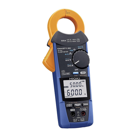
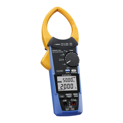
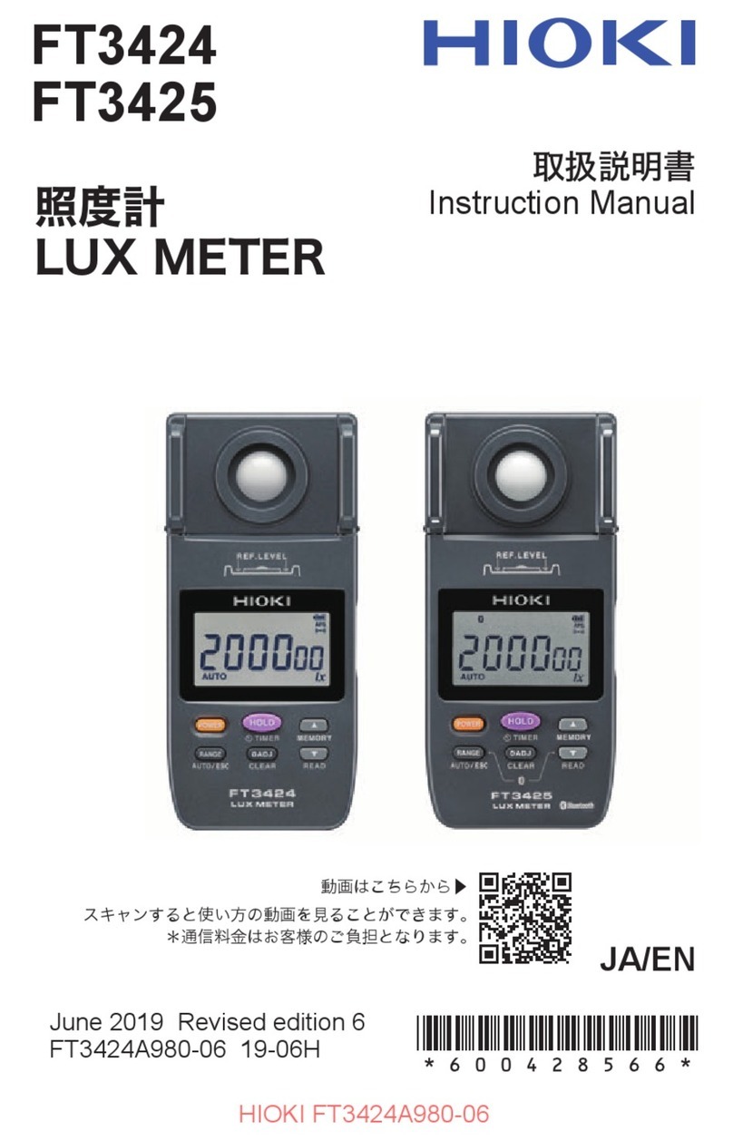
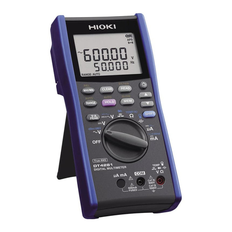
Hioki CM4141-50 User manual

CM4141-50
Instruction Manual
AC CLAMP METER
EN
Dec. 2021 Edition 1
CM4141C961-00 21-12H
Read carefully before use.
Keep for future reference.
CM4141-50
Instruction Manual
AC CLAMP METER
EN
Dec. 2021 Edition 1
CM4141C961-00 21-12H
Read carefully before use.
Keep for future reference.
www.hioki.com/
www.hioki.com/
HIOKI CM4141C961-00

HIOKI CM4141C961-00

i
CM4141C961-00
Contents
Introduction.................................................................................................................1
Notations.....................................................................................................................2
Checking Package Contents .....................................................................................7
Options........................................................................................................................8
Safety Information....................................................................................................11
Operating Precautions.............................................................................................12
1 Overview 19
1.1 Product Overview and Features ..........................................................19
1.2 Part Names ............................................................................................20
2 Making Measurements 21
2.1 Inspection Before Measurement..........................................................21
2.2 Installing Batteries and the Z3210 Wireless Adapter.........................22
Installation procedure ............................................................................................25
2.3 Use of Test Leads..................................................................................28
L9300 Test Lead (accessory).................................................................................30
HIOKI CM4141C961-00

ii
Contents
2.4 Current Measurement ...........................................................................32
Manual hold, automatic hold..................................................................................33
Switching the ranges .............................................................................................36
Maximum, minimum, average, and peak Values ...................................................37
Filter function .........................................................................................................38
Inrush current (AC inrush) .....................................................................................39
2.5 Various Other Measurement Functions ..............................................40
2.6 LCD Backlight, Automatic Power Save (APS) ....................................44
2.7 DC High V Probe Mode .........................................................................45
2.8 Wireless Communications Function (Z3210 required) ......................49
Using GENNECT Cross.........................................................................................49
Z3210-to-Excel®direct data entry function
(Excel®direct input function, HID function) ...........................................................54
2.9 Rotary Switch Combinations ...............................................................58
3 Specications 61
3.1 GeneralSpecications .........................................................................61
3.2 InputSpecications,MeasurementSpecications ...........................64
3.3 Accuracy table.......................................................................................72
HIOKI CM4141C961-00

iii
Contents
4 Maintenance and Service 89
4.1 Troubleshooting ....................................................................................89
4.2 Error and Operation Display ................................................................92
4.3 Cleaning .................................................................................................93
Index 95
HIOKI CM4141C961-00

iv
Contents
HIOKI CM4141C961-00

1
Introduction
Introduction
Thank you for choosing the Hioki CM4141-50 AC Clamp Meter. To ensure your ability to get the
most out of this instrument over the long term, please read this manual carefully and keep it
available for future reference.
Read the separate document “Operating Precautions” carefully before using the instrument.
Latest edition of instruction manual
The contents of this manual are subject to change, for example as a result of product
improvements or changes to specications.
The latest edition can be downloaded from Hioki’s website.
https://www.hioki.com/global/support/download
Target audience
This manual has been written for use by individuals who use the product in question or who
teach others to do so. It is assumed that the reader possesses basic electrical knowledge
(equivalent to that of someone who graduated from the electrical program at a technical high
school).
HIOKI CM4141C961-00

2
Notations
Trademarks
• Microsoft Excel is a registered trademark or a trademark of Microsoft Corporation in the United States and
other countries.
• The Bluetooth®word mark and logos are registered trademarks owned by Bluetooth SIG, Inc. and any use
of such marks by Hioki E.E. Corporation is under license. Other trademarks and trade names are those of
their respective owners.
Notations
Safety notations
In this document, the severity levels of risk and hazard are classied as follows.
DANGER
Indicates an imminently
hazardous situation that,
if not avoided, will result in
death or serious injury.
IMPORTANT
Indicates information or
content that is particularly
important from the stand
point of operating or
maintaining the instrument.
WARNING
Indicates a potentially
hazardous situation that, if
not avoided, could result in
death or serious injury.
Indicates a high-voltage
hazard. Failure to verify
safety or improper handling
of the instrument could lead
to electric shock, burn injury,
or death.
HIOKI CM4141C961-00

3
Notations
CAUTION
Indicates a potentially
hazardous situation that, if
not avoided, could result in
minor or moderate injury.
Indicates the presence of a
hazard caused by a strong
magnet. The product could
interfere with the proper
operation of electronic
medical devices such as
pacemakers.
NOTICE
Indicates potential risks of
damage to the supported
product (or to other
property).
Indicates an action that
must not be performed.
Indicates an action that
must be performed.
HIOKI CM4141C961-00

4
Notations
Symbols shown on the instrument
Indicates the presence of a potential hazard. For more information about locations where
this symbol appears on instrument components, see the “Operating Precautions” (p.12),
warning messages listed at the beginning of operating instructions, and the accompanying
document entitled “Operating Precautions.”
Indicates that a dangerous voltage is generated from this terminal.
Indicates that the product can be attached or detached while the circuit is live.
Indicates alternating current (AC).
Indicates direct current (DC).
Indicates the grounding terminal.
Indicates the instrument is protected throughout by double insulation or reinforced insulation.
HIOKI CM4141C961-00

5
Notations
Symbols for various standards
Indicates that the product is subject to the Waste Electrical and Electronic Equipment (WEEE)
Directive in EU member nations. Dispose of the product in accordance with local regulations.
Indicates that the product complies with standards imposed by EU directives.
Screen display
The instrument screen displays the alphanumeric characters as follows.
1 2 3 4 5 6 7 8 9 0
A B C D E F G H I J K L M N O P Q R S T U V W X Y Z Some displays may be different from
those indicated on the left.
: Wire break detected
HIOKI CM4141C961-00

6
Notations
Accuracy labeling
Instrument accuracy is expressed by dening a percentage of the reading, a percentage of full scale, a
percentage of the setting, or a limit value for errors in terms of digits.
Reading
(display value)
Indicates the value displayed by the instrument.
Limit values for reading errors are expressed as a percentage of the reading (“% rdg”).
Full scale
(maximum
display value)
Indicates the maximum display value for each measurement range. Measurement range
values for the instrument indicates that maximum display value. Limit values for full-scale
errors are expressed as a percentage of full scale (“% f.s.”).
Other notations
Indicates a buzzer sound (either intermittent or continuous).
(p. ) Indicates the page number to reference.
*Indicates additional information is described below.
HIOKI CM4141C961-00

7
Checking Package Contents
When you receive the instrument, inspect it to ensure that no damage occurred during shipment. Pay
particular attention to included accessories, panel keys, and terminals. If you nd any damage or discover
that the instrument does not perform as indicated in its specications, please contact your authorized Hioki
distributor or reseller.
CM4141-50
AC Clamp Meter
L9300 Test Lead (p.30)
C0203 Carrying Case
LR03 Alkaline batteries ×2
Instruction Manual (this manual)
Operating Precautions (0990A907)
HIOKI CM4141C961-00

8
Options
Options
The options listed below are available for the instrument. To order an option, please contact your
authorized Hioki distributor or reseller.
Options are subject to change. Check Hioki’s website for the latest information.
Connection cables
L9300 Test Lead*1
L4933 Contact Pin Set*6
L4934 Small Alligator Clip Set*5
L9207-10 Test Lead*1
When attaching the L4933 or L4934 to test leads, set the test
leads to the measurement category II conguration (for the
L9207-10, remove the sleeves).
HIOKI CM4141C961-00

9
Options
DT4910 Thermocouples (K)
L4935 Alligator Clip Set*2
L9243 Grabber Clip*9
L4936 Bus Bar Clip Set*4
L4937 Magnetic Adapter Set*3
L4932 Test Pin Set*1
L4930 Connection Cable Set*2
(length: 1.2 m)
L4931 Extension Cable Set*2
(length: 1.5 m, with the coupling
connector)
L4938 Test Pin Set*7
L4939 Breaker Pin Set*10
9804 Magnetic Adapter*8
P2000 DC High Voltage Probe*11
*1: CAT IV 600 V/CAT III 1000 V/CAT II 1000 V, 10 A *6: 30 V AC/60 V DC, 3 A
*2: CAT IV 600 V/CAT III 1000 V, 10 A *7: CAT III 600 V/CAT II 600 V, 10 A
*3: CAT III 1000 V, 2 A *8: CAT IV 1000 V, 2 A
*4: CAT III 600 V, 5 A *9: CAT II 1000 V, 1 A
*5: CAT III 300 V/CAT II 600 V, 3 A *10: CAT III 600 V, 10 A
*11: CAT IV 1000 V/CAT III 2000 V
HIOKI CM4141C961-00

10
Options
Carrying cases
The instrument, test leads, and the instruction manuals can be accommodated.
C0203 Carrying Case C0207 Carrying Case (bag type)
Z3210 Wireless Adapter
Connecting the Z3210 to the instrument enables the wireless
communication function.
See “2.8 Wireless Communications Function (Z3210 required)” (p.49).
HIOKI CM4141C961-00

11
Safety Information
Safety Information
Measurement categories
The instrument conforms to the safety requirements for CAT III 1000 V and CAT IV 600 V
measuring instruments.
T
Service entrance
Service drop
CAT IV
(≤600 V)
Power meter
Fixed installation
Outlet
CAT II
(≤1000 V)
CAT III
(≤1000 V)
Internal wiring
Distribution panel
HIOKI CM4141C961-00

12
Operating Precautions
Observe the following precautionary information to ensure that the instrument can be used
safely and in a manner that allows it to perform as described in its specications. Carefully
read the separate document entitled “Operating Precautions” before use. Use of the instrument
should conform not only to its specications, but also to the specications of all accessories,
options, and other equipment in use.
DANGER
Do not touch the section beyond the barrier during operation.
Failure to do so could cause the operator to experience an electric shock.
See “1.2 Part Names” (p.20).
Do not measure any current in excess of the derating.
Doing so can cause overheating of the sensor, resulting in bodily injury, re, or
damage to the instrument.
See “Frequency derating” (p.65).
The maximum measurement current varies with the frequency, and the current
that can be measured continuously is limited. Operating the instrument at less
than this limitation is referred to as derating.
HIOKI CM4141C961-00

13
Operating Precautions
DANGER
Do not apply a voltage across the measurement terminals
when the resistance measurement, continuity check,
diode check, capacitance measurement, or temperature
measurement function is selected
Doing so could cause an electric shock or damage the instrument. To avoid
electrical accidents, turn off the circuit before measuring it.
Conrm that the white portion (insulation layer) inside the
cable is not exposed.
Using the instrument with a color inside its cable exposed could cause the
operator to experience an electric shock.
HIOKI CM4141C961-00

14
Operating Precautions
WARNING
Do not allow the instrument to get wet.
Do not take measurements with wet hands.
Failure to do so could cause the operator to experience an electric shock.
When using the instrument while connected to test leads,
do not make measurements that exceed either of the ratings
indicated on the instrument or on the test leads, whichever is
lower.
Using the instrument to make measurements that exceed either rating could
cause the operator to experience an electric shock.
HIOKI CM4141C961-00
Table of contents
Other Hioki Measuring Instrument manuals

Hioki
Hioki LR5041 User manual

Hioki
Hioki 9272-05 User manual

Hioki
Hioki CT6700 User manual

Hioki
Hioki 9290-10 User manual

Hioki
Hioki PW3365-20 User manual

Hioki
Hioki PQ3100-91 User manual

Hioki
Hioki 9274 User manual

Hioki
Hioki 3246-60 User manual

Hioki
Hioki FT6381 User manual

Hioki
Hioki MR8880-20 User manual