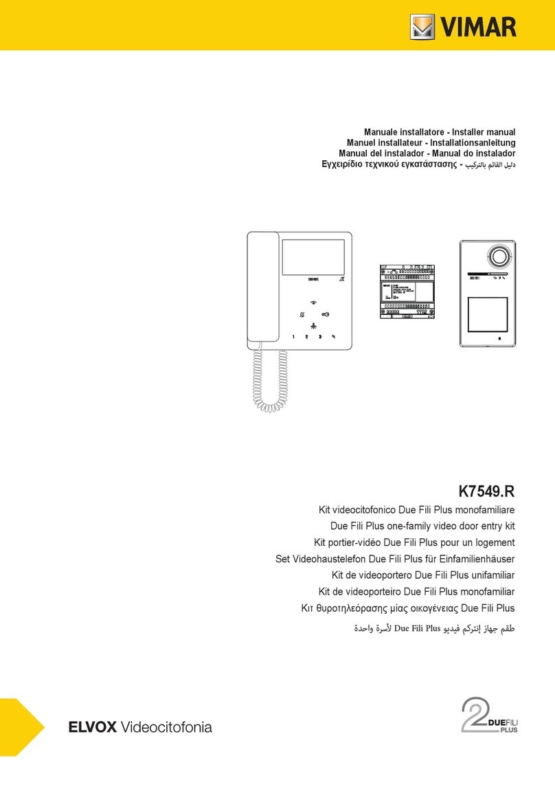
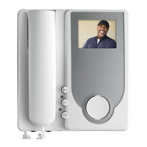
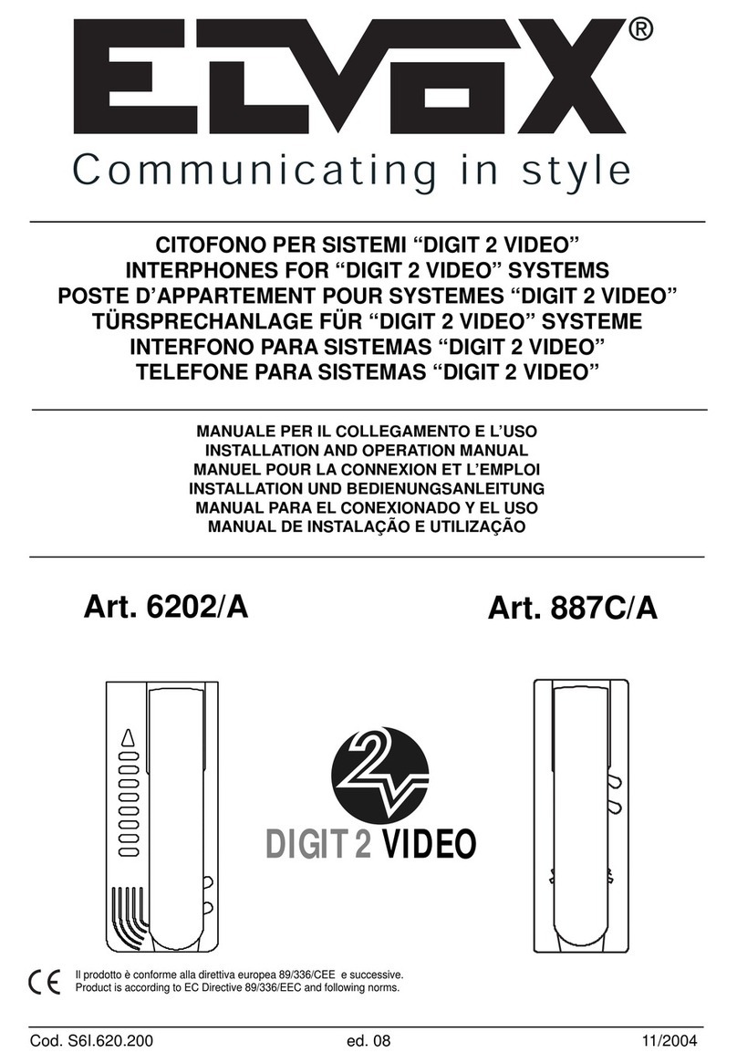
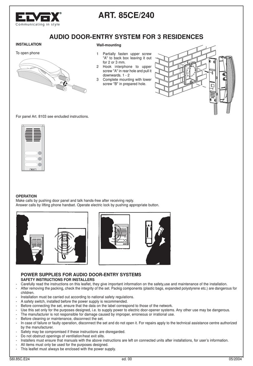
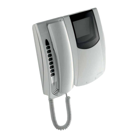
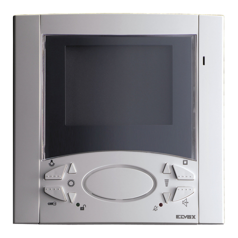
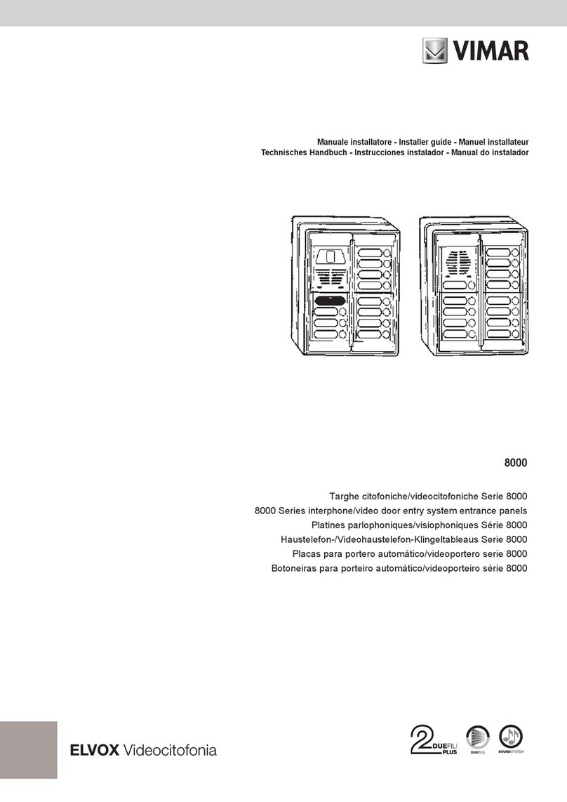
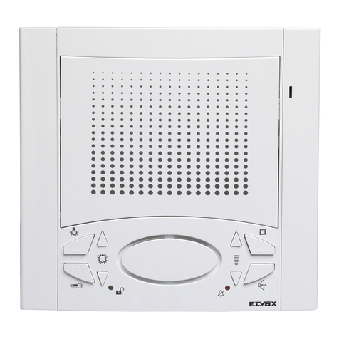
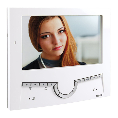
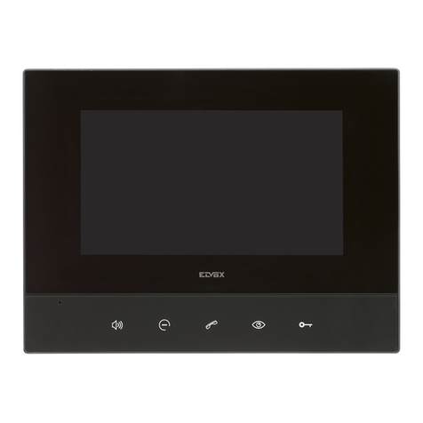
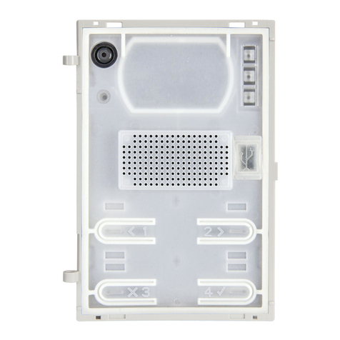
Elvox PETRARCA 6002 User manual

Art. 6002
MANUALE PER IL COLLEGAMENTO
WIRING INSTRUCTIONS
INSTRUCTIONS POUR LA CONNEXION
ANWEISUNGEN FÜR DEN ANSCHLUSS
INSTRUCCIONES PARA EL CONEXIONADO
INSTRUÇÕES PARA A LIGAÇÃO
MONITOR SERIE PETRARCA
PETRARCA SERIES MONITOR
MONITEUR SERIE PETRARCA
MONITOR BAUREIHE PETRARCA
MONITOR SERIE PETRARCA
MONITOR DA SÉRIE PETRARCA
Cod. S6I.600.200 RL. 00 9/2008
Il prodotto è conforme alla direttiva europea 2004/108/CE e successive.
Product is according to EC Directive 2004/108/CE and following norms.

MOUNTING OF MONITOR WITH INTERPHONE
- Flush-mount bracket type 6145 at 1,40 m from the floor.
(see Fig. 1).
- Open the interphone splitting the cabinet from the lower
part by pressing with a screwdriver (see fig. 2 and 3).
- Insert the connection card provided with monitor type 6002
inside the interphone (see fig. 4) and connect the card to
the interphone by using connectors CN1 (card) and CN2
(interphone).
- Insert the interphone lower part in the bracket left hand
side inserting it in proper seats and pulling it downward
until its complete locking (see Fig. 5)
- Carry our connections on interphone and monitor card ter-
minals.
- Connect the monitor cabling to the connecting card by
means of card connector CN2 (see Fig. 6).
- Insert monitor laying it on proper seats and pulling it
downward until its complete locking (see Fig. 6).
- Close the interphone by hooking the cabinet to the bottom
upper part and by pressing on the cabinet lower side until
the closing snap .
- To remove the interphone or monitor from the bracket,
operate on the security lock with a screw driver and extract
them following the arrow direction (see Fig. 7).
MONTAGGIO MONITOR CON CITOFONO
- Fissare a parete la staffa art. 6145 ad un'altezza di circa
1,40 m dal pavimento (vedi fig. 1)
- Aprire il citofono separando il cofano superiore dalla parte
inferiore facendo pressione con un cacciavite (vedi fig. 2 e
3)
- Inserire all'interno del citofono la scheda di connessione
fornita con il monitor art. 6002 (vedi fig. 4) e collegare la
scheda al citofono tramite i connettori CN1 (scheda) e
CN2 (citofono).
- Inserire il fondo del citofono sulla parte sinistra della staffa
infilandolo nelle apposite sedi e tirandolo verso il basso
fino al suo completo blocaggio (vedi fig. 5).
- Eseguire i collegamenti sui morsetti del citofono e della
scheda del monitor.
- Collegare il cablaggio del monitor alla scheda di connes-
sione tramite il connettore CN2 della scheda (vedi fig. 6).
- Inserire il monitor appoggiandolo nelle apposite sedi e
tirandolo verso il basso fino al suo completo bloccaggio
(vedi fig. 6).
- Chiudere il citofono agganciando il cofano alla parte supe-
riore del fondo e premere sulla parte inferiore del cofano
fino al raggiungimento dello scatto.
Per estrarre il citofono o il monitor dalla staffa, agire con
un cacciavite sulla linguetta di sicurezza ed estrarli
seguendo il senso delle frecce (vedi fig. 7).
Der Monitor der Baureihe PETRARCA Art. 6002 kann mit
den Haustelefonen Art. 6202 für Video-Türsprechanlagen der
Baureihen ““DIGIT 2 VIDEO”.
D
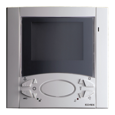
The PETRARCA monitor Art. 6002 may be combined with
interphones 6202 in video door entry installations from the
“DIGIT 2 VIDEO”.
GB
2
Il monitor della serie PETRARCA Art. 6002 è abbinabile ai
citofoni 6202 per impianti videocitofonici delle serie “DIGIT 2
VIDEO”.
I
Le moniteur de la série PETRARCA Art. 6002 peut être asso-
cié aux postes d’appartement 6202 pour les installations de
portiers vidéo de la gamme “DIGIT 2 VIDEO”.
F
TECHNICAL CHARACTERISTICS OF ART. 6002
- Slim-line surface wall-mounted monitor with 4” flat screen
complete with circuit board for interphones
- Minimum supply voltage: 15 Vdc (maximum 20 Vdc)
- Video signal standard: CCIR with 625 lines and 50 frames
(EIA standard available on request)
- Passband: 4 MHz.
CARATTERISTICHE TECNICHE ART. 6002
- Monitor da esterno parete a basso profilo con schermo 4”
piatto completo di circuito per citofoni.
- Tensione di alimentazione minima 15V c.c. (massima
20Vc.c.)
- Segnale video standard CCIR 625 linee, 50 quadri (su
richiesta standard/EIA)
- Banda passante 4 MHz
CARACTERISTIQUES TECHNIQUES ART. 6002
- Moniteur mural à bas profil avec écran 4” plat, complet de
circuit pour postes d'appartament
- Tension d’alimentation minimum 15 Vcc (20 Vcc maxi-
mum).
- Signal vidéo standard CCIR 625 lignes, 50 cadres (sur
demande standard EIA).
- Bande passante 4 MHz.
TECHNISCHE EIGENSCHAFTEN ART. 6002
- Aufputz-Monitor mit niedrigem Profil und 4” Flachschirm
komplett mit Schaltkreis für Haustelefonen
- Versorgungsspannung mindestens 15Vdc (maximal
20Vdc)
- Videosignal CCIR Norm 625 Zeilen, 50 Bilder (auf
Wunsch EIA Norm)
- Auflösung 4MHz
INSTALLATION DES MONITORS MIT HASUTELEFON
- Der Halter Art. 6145 1,40 m Höhe vom Boden einmauern
(siehe Abb. 1)
- Das Haustelefon durch Trennen und Drücken den
Oberenteil des Gehäuse mittels eines Schraubenziehers
öffnen (siehe Abb. 2 und 3).
MONTAGE DU MONITEUR AVEC POSTE D'APPARTEMENT
- Murer l'étrier Art. 6145 à une hauteur d'environ 1,40 m du
sol.
- Ouvrir le poste d'appartement en séparant le meuble supé-
rieur de la partie inférieure en effectuant une pression
avec un turnevis (voir Fig. 2 et 3).

3
- Insérer à l'intérieur du poste d'appartement la carte de
connection fournie avec le moniteur Art. 6002 (voir Fig. 4)
et raccorder la carte au poste d'appartement au moyen
des connecteurs CN1 (carte) et CN2 (poste d'apparte-
ment).
- Insérer le fond du poste d'appartement sur la partie gau-
che de l'étrier en l'insérant sur les emplacements appro-
priés et en le tirant vers le bas jusqu'à son complet bloca-
ge (voir fig. 5).
- Efectuer les raccordements sur les bornes du poste d'ap-
partement et de la carte du moniteur.
- Brancher le câble du moniteur à la carte de raccordement
au moyen du connecteur CN2 de la carte (voir Fig. 6).
- Insérer le moniteur en l'appuyant sur les emplacements
appropriés et en le tirant vers le bas jusqu'à son complet
blocage (voir fig. 6).
- Fermer le poste d'appartement en accrochant le meuble à
la partie supérieure du fond et en appuyant sur la partie
inférieure du meuble jusqu'à ouir le clic de fermeture.
- Pour extraire le poste d'appartement ou le moniteur de l'é-
trier, agir avec un tournevis sur la clavette de sécurité et
les extraire en suivant la direction des fléches (voir Fig. 7).
- Beim Haustelefon die mit dem Monitor Art. 6002 mitgelie-
ferte Anschlußkarte einsetzen (siehe Abb. 4) und durch die
Verbinder CN1 (Karte) und CN2 (Haustelefon) die Karte
anschließen.
- Den Haustelefonboden in die linke Seite des Halters ein-
setzen und ihn in die entsprechende Sitze einfügen und
ihn nach unten bis ihrer volkommenen Sperre ziehen
(siehe Abb. 5).
- Die Anschlusse an die Haustelefonklemmen und an die
Monitorkarte ausführen.
- Das Monitorkabel durch den Karteverbinder CN2 an die
Anschlusskarte anschließen. (siehe Abb. 6).
- Lehen den Monitor an die passenden Sitze und ihn (durch
dessen Ziehen nach unten bis zu seiner volkommener
Sperre) einsetzen (siehe Abb. 6).
- Das Haustelefon durch Einhaken der oberer Seite des
Gehäuses an die oberer Seite des Bodens schließen und
die Unterenseite des Gehäuses drücken bis sie hörbar ein-
rastet.
- Um das Haustelefon und den Monitor aus dem Halter
herauszuziehen, mit einem Schraubenzieher an die
Sichereheitfeder wirken und durch Folgen der Pfeilrichtung
das Haustelefon und den Monitor herausziehen.
O monitor da série PETRARCA Art. 6002 pode ser acoplado
aos telefones 6202 para instalações de video-porteiro das
gamas “DIGIT 2 VIDEO”.
P
El monitor della serie PETRARCA Art. 6002 se puede aco-
plar a los interfonos Art. 6202 para instalaciones de video-
portero de la gama “DIGIT 2 VIDEO”.
E
CARACTERÍSTICAS TÉCNICAS ART. 6002
- Monitor de externo pared a bajo perfil con pantalla 4”
plana completo de circuitos para teléfonos
- Tensión de alimentación mínima 15V c.c. (máxima 20V
c.c.)
- Señal vídeo Standard CCIR 625 líneas, 50 cuadros
(según pedido standard/EIA)
- Banda pasante 4 MHz
CARACTERÍSTICAS TÉCNICAS ART. 6002
- Monitor de montagem saliente de baixo perfil com écran
plano de 4” completo de circuitos para interfones.
- Tensão de alimentação mínima 15V c.c. (máxima 20V
c.c.)
- Sinal de vídeo standard CCIR 625 linhas, 50 imganes (sob
pedido standard EIA)
- Banda passante: 4 MHz.
MONTAJE DEL MONITOR CON INTERFONO
- Empotrar el soporte art. 6145 a una altura de cerca 1,40
m. del piso (ver Fig. 1).
- Abrir el interfono separando el mueble superior de la parte
inferior haciendo presión con un destornillador (ver Fig. 2 y
3).
- Insertar en el interior del interfono la ficha de conexión pro-
vista con el monitor Art. 6002 (ver Fig. 4) y conectar la
ficha al interfono por medio de los conectores CN1 (ficha)
y CN2 (interfono).
- Insertar el fondo del interfono en la parte izquerda del
soporte insertándolo en los asientos apropiados y jalándo-
lo hacia abajo hasta su completo bloqueo (ver Fig. 5).
- Efectuar las conexiones a los bornes del interfono y de la
ficha del monitor.
- Conectar el cable del monitor a la ficha de conexión por
medio del conector CN2 de la ficha (ver Fig. 6).
- Insertar el monitor apoyándolo en los asientos apropiados
y jalándolo hacia abajo hasta su completo bloqueo (ver
Fig. 6).
- Cerrar el interfono enganchando el mueble a la parte
superior del fondo y presionando la parte inferior del mue-
ble hasta oir el disparo di cierre.
- Para extraer el interfono o el monitor desde el soporte,
actuar con un destornillador en la lengüeta de seguridad y
extraerlos siguiendo el sentido de las flechas (ver Fig. 7)
MONTAGEM DO MONITOR COM INTERFONE
- Embeber o suporte Art. 6145 a uma altura de 1,40 m do
chao (ver Fig. 1).
- Abrir o interfone separando o móvel superior da parte infe-
rior efetuando uma pressão com uma chave de parafusos
(ver Fig. 2 e 3).
- Inserir no interior do interfone a placa de ligação fornecida
com o monitor Art. 6002 (ver Fig. 4) e ligar a placa ao
interfone através dos conetores CN1 (placa) e CN2
(interfone).
- Inserir o fundo do interfone na parte ezquerda do suporte
inserindo-o nas sedes apropriadas e tirando-o para baixo
até o suo completo bloqueio.
- Efetuar as ligações nos terminais do interfone e da placa
do monitor.
- Ligar o cabo do monitor à placa de ligação através do
conetor CN2 da placa (ver Fig. 6).
- Inserir o monitor apoiando-o nas sedes apropriadas e
tirando-o para baixo até o suo completo bloqueio (ver
fig.6).
- Fechar o interfone enganchando o móvel à parte superior
do fundo e premir na parte inferior do móvel até ouvir o
disparo de fecho.
- Para extrair o interfone o ou monitor do soporte, obrar com
uma chave de parafusos na lingueta de segurança e
extrai-los seguindo a direção das setas (ver Fig. 7).
ELVOX
MC68HC908
JK3CDW
2J88YXAA0252
ART.6202
4
ELVOX
MC68HC908
JK3CDW
2J88YXAA0252
ART.6202
Fig. 4
Fig. 5
1,40
Fig. 1
Fig. 3
Fig. 2
Art. 6145

5
Fig. 7
Fig. 6
DIMENSIONI MONITOR E REGOLAZIONI:
MONITOR DIMENSIONS AND ADJUSTMENTS:
DIMENSIONS DU MONITEUR ET RÉGLAGES:
ABMESSUNGEN UND EINSTELLUNG DES MONITORS:
DIMENSIONES MONITOR Y REGULACIONES:
DIMENSÕES DO MONITOR E REGULAÇÕES:
135 mm
226 mm
48 mm
Contrasto
Contrast
Contraste
Kontrast
Contraste
Contraste
Luminosità
Brightness
Luminosité
Helligkeit
Luminosidad
Luminosidade

6
Montaggio del kit di trasformazione da tavolo per soli monitor:
Desk-top conversion kit for monitors only:
Montage du kit de transformation en version de table pour seuls moniteurs:
Montage des Umrüst-Bausatzes für Tischaufstellung nur des Monitors:
Montaje del kit de transformación en sobremesa para solos monitores:
Montagem do kit de transformação para a versão de mesa só para monitores:
Art. 6A41
Montaggio del kit di trasformazione da tavolo per monitor e citofoni:
Desk-top conversion kit for monitor and interphones:
Montage du kit de transformation de table pour moniteur et postes d’appartement:
Montage des Umrüst-Bausatzes für Tischaufstellung von Monitor und Haustelefon:
Montaje del kit de transformación en sobremesa para monitor e interfono:
Montagem do kit de transformação para a versão de mesa para monitores e telefones de porteiro:
ELVOX
Art. 6142

7
SCHEMA DI COLLEGAMENTO IMPIANTO DUE FILI DI UN PORTIERE ELETTRICO A DUE TARGHE CON MONTANTE
MONITOR SERIE PETRARCA ART. 6002 E DISTRIBUTORE AL PIANO ART. 732D CON ALIMENTAZIONE LOCALE.
WIRING DIAGRAM FOR TWO WIRE DOOR ENTRY SYSTEM WITH TWO DOOR ENTRY PANELS AND PETRARCA
SERIES MONITOR RISER ART. 6002 AND 4 OUTPUT SPLITTER ART. 732D WITH LOCAL SUPPLY VOLTAGE.
SCHEMA DE CONNEXION INSTALLATION A DEUX FILS D'UN PORTIER ELECTRIQUE A DEUX PLAQUES AVEC COLONNES
MONITEURS SERIE
PETRARCA ART. 6002
ET DISTRIBUTEUR A L'ETAGE ART. 732D AVEC ALIMENTATION LOCALE.
ANSCHLUSSSCHEMA FÜR EINE 2-DRAHT VIDEOTÜRSPRECHANLAGE MIT ZWEI KLINGELTABLEAUS, MIT MONITORSPRECHSTEL-
LEN DER SERIE
PETRARCA ART. 6002
UND 4-FACH VERTEILER ART. 732D, SOWIE ZENTRALER SPANNUNGSVERSORGUNG.
ESQUEMA PARA EL CONEXIONADO DE UNA INSTALACIÓNA DOS HILOS PARA UN PORTERO ELÉCTRICO CON DOS PLACAS,
MONTANTE MONITORES SERIE PETRARCA ART. 6002 Y DISTRIBUIDOR A LA PLANTA ART. 732D CON ALIMENTACIÓN LOCAL.
ESQUEMA DE LIGAÇÃO PARA PORTEIROS ELÉCTRICOS AUDIO COM DOIS FIOS E COLUNA MONTANTE MONITO-
RES DA SÉRIE PETRARCA ART. 6002, DISTRIBUIDOR ART. 732D COM ALIMENTAÇÃO LOCAL
INV1 V1 V2V2
V4V4 V3V3
AB
CD
OUT
MONTANTE IN - CABLE RISER IN
STEIGLEITUNG EINGANG - MONTANT IN
MONTANTE IN
MONTANTE OUT - CABLE RISER OUT
STEIGLEITUNG AUSGANG - MONTANT OUT
MONTANTE OUT
TABELLA CAVI
CAVI SEZIONE DISTANZA DISTANZA
Doppino 0,25mm² max 100mt max 30mt
Doppino (Art. 732F) 0,25mm² max 100mt max 60mt
Alimentazione
1mm² max 100mt max 60mt
Doppino + alimentazione 0,50mm² +
max 100mt max 60mt
monitor (Art. 732G) 1mm²
DISTRIBUTORE
DISTRIBUTOR
DISTRIBUTEUR
VERTEILER
DISTRIBUIDOR
Art. 732D
Ponticelli presenti nel distributore Art. 732D. Da
togliere solo se viene usata la sua uscita vicina.
Jumpers on splitter Art. 732D. To remove only if its
close output is used.
Barrettes presentes sur le distributeur Art. 732D. À
enlever seulement si l'on utilise sa sortie prochaine
Jumper im Verteiler Art. 732D. Nur entfernen, wenn
der entsprechende Ausgang verwendet wird.
Puentes presentes en el distribuidor Art. 732D, Para
quitar sólo si se utiliza su salida cercana.
Pontes presentes no distribuidor Art. 732D, para reti-
rar só se usa-se a sua saída vezinha.
A - TARGA DIGITALE VIDEO SERIE GALILEO
ART. 8C46-8C42-8C43-8C45-3C42-3C43-3C46-3C45
B - PULSANTE SUPPLEMENTARE SERRATURA
C - SERRATURA ELETTRICA 12V ~ 1A
D - TRASFORMATORE ART. 832/030
E - RELÈ ART. 170/050
A- VIDEO DIGITAL GALILEO SERIES ENTRANCE PANELS
ART. 8C46-8C42-8C43-8C45-3C42-3C43-3C46-3C45
B- OUTDOOR PUSH-BUTTON
C- 12V A.C. 1A ELECTRIC LOCK
D - TRANSFORMER ART. 832/030
E - RELAY ART. 170/050
A-
DIGITAL-VIDEOKLINGELTABLEAU DER SERIE GALILEO
ART. 8C46-8C42-8C43-8C45-3C42-3C43-3C46-3C45
B - ZUSATZTASTE FÜR TÜRÖFFNER
C - ELEKTRISCHES TÜRSCHLOSS 12V ~ 1A
D - TRANSFORMATOR ART. 832/030
E - RELAIS ART. 170/050
A - PLAQUE DIGITALE VIDEO SERIE GALILEO
ART. 8C46-8C42-8C43-8C45-3C42-3C43-3C46-3C45
B - TOUCHE SUPPLEMENTAIRE GACHE
C - GACHE ELECTRIQUE 12 V ~ 1A
D - TRANSFORMATEUR ART. 832/030
E - RELAIS ART. 170/050
A - PLACA VÍDEO SERIE GALILEO
ART. 8C46-8C42-8C43-8C45-3C42-3C43-3C46-3C45
B - PULSADOR SUPLEMENTARIO CERRADURA
C - CERRADURA ELÉCTRICA 12V ~ 1A
D - TRANSFORMADORART. 832/030
E - RELÈ ART. 170/050
A - BOTONEIRA VIDEO SERIE GALILEO
ART. 8C46-8C42-8C43-8C45-3C42-3C43-3C46-3C45
B - BOTÃO SUPLEMENTAR DO TRINCO
C - TRINCO ELÉCTRICO 12V ~ 1A
D - TRANSFORMADOR ART. 832/030
E - RELÈ ART. 170/050
TABLEAU DES CABLES
CABLES SECTION DISTANCE DISTANCE
Boucle 0,25mm² max 100mt max 30mt
Boucle (Art. 732F) 0,25mm² max 100mt max 60mt
Alimentation 1mm² max 100mt max 60mt
Boucle
+
alimentation
0,50mm² +
max 100mt max 60mt
moniteur (Art. 732G) 1mm²
PROSPECTO CABLES
CABLES SECCIÓN
DISTANCIA DISTANCIA
Cable dobleado 0,25mm² max 100mt max 30mt
Cable dobleado (Art. 732F)
0,25mm² max 100mt max 60mt
Alimentación
1mm² max 100mt max 60mt
Cable dobleado + alimentación
0,50mm² +
max 100mt max 60mt
monitor (Art. 732G) 1mm²
CABLE TABLE
CABLES SECTION DISTANCE DISTANCE
Two wire cable 0,25mm² max 100mt max 30mt
Two wire cable (Art. 732F)
0,25mm² max 100mt max 60mt
Supply voltage
1mm² max 100mt max 60mt
Two wire cable + supply voltage
0,50mm² +
max 100mt max 60mt
monitor (Art. 732G) 1mm²
KABELTABELLE
KABEL
QUERSCHNITT
ENTFERNUNG
ENTFERNUNG
2-Draht Leitung 0,25mm² max 100mt max 30mt
2-Draht Leitung (Art. 732F)
0,25mm² max 100mt max 60mt
Netz 1mm² max 100mt max 60mt
2-Draht Leitung
+
Netz
0,50mm² +
max 100mt max 60mt
Monitor (Art. 732G) 1mm²
TABELA CABOS
CABOS SECÇÃO
DINSTÂNCIA DINSTÂNCIA
Cabo dobleado 0,25mm² max 100mt max 30mt
Cabo dobleado (Art. 732F)
0,25mm² max 100mt max 60mt
Alimentação
1mm² max 100mt max 60mt
Cabo dobleado + alimentação
0,50mm² +
max 100mt max 60mt
monitor (Art. 732G) 1mm²

R
ITALY
ART.732D
DISTRIBUTOREVIDEOSERIEVI-DIGIT2W
VIDEODISTRIBUTORVI-DIGIT2WSERIES
V3 V3
OUTMONTANTE
V4
V4
V1 V1 V2 V2
INMONTANTE
2
13
456
789
R0C
X
ELVOX
2
13
456
789
R0C
X
ELVOX
V1 V1 V2V2
V4V4 V3V3
AB
CD
-+U+I B CA PRID
IN
OUT
V1 V1 V2V2
V4V4 V3V3
DC
B
-+U+I B CAPRID
OUT
IN
L1L2
A
B
PS
M2
+E
S2
S1
F2
F1
L2
L1
+
A
A
B
PRI +E -E
6
8
V2
-E
V1
M1
O15
(15)
(O)
PRI +E -E
O15
+U-+IBAC PRID-
+
L1
L2
2
3
1
+I-+U CA B D PRI
To phone
To monitor
Mors.
To phone
L1
L2
To monitor
-
+
Mors.
3
2
11
2
3
L1
L2
-
+
Mors.
To phone
To monitor
To phone
L1
-
+
L2
To monitor
1
3
2
Mors.
+12
A
PS
V1
6
8
M2
V2
M1
S2
L1
L2
+
-E (O)
S1
(15)
+12
+E
F1
F2
C
PRI O 15
4123 5
PRI O 15
52134
C
A
8
N° vc4049
MONTANTE IN
MONTANTE OUT
N.B. SCATOLA DI COLLEGAMENTO CAVI
DELLE DUE TARGHE BISOGNA RISPETTA-
RE LA POLARITA’ DEI CAVI, PER CUI BISO-
GNERA’ COLLEGARE I CAVI RISPETTANDO
LE SERIGRAFIE SCRITTE (+L1 CON +L1
ECC.)
NOTE: CABLE CONNECTION BOX FOR
TWO DOOR ENTRY PANELS.PAY ATTEN-
TION TO THE CABLE POLARITY, THEREFO-
RE CONNECT THE CABLES ACCORDING
TO THE SERIGRAPHS MARKED: (+L1 with
L1 etc….).
N.B. BOITE DE CONNEXION DES CABLES
DES TROIS PLAQUES IL FAUT RESPEC-
TER LA POLARITE DES CABLES, DONC IL
FAUDRA CONNECTER LES CABLES EN
RESPECTANT LES SERIGRAPHIES
ÉCRITES (+L1 AVEC +L1 ETC)
HINWEIS: KABELANSCHLUSS FÜR ZWEI
KLINGELTABLEAUS: DIE RICHTIGE
POLUNG DER KABEL BEACHTEN,
DESHALB MÜSSEN DIE ADERN UNTER
BEFOLGUNG DER AUFSCHRIFTEN ANGE-
SCHLOSSEN WERDEN (+L1 MIT +L1 USW.)
N.B. REGLETA DE CONEXIONES CABLES
DE LAS DOS PLACAS. HAY QUE RESPEC-
TAR LA POLARIDAD DE LOS CABLES, POR
LO TANTO HAY QUE CONECTAR LOS
CABLES RESPECTANDO LAS SERIGRA-
FIAS ESCRITAS (+L1 CON + L1 ETC.)
N.B. CAIXA DE LIGAÇÃO CABOS DAS
DUAS BOTONEIRAS. EFETUAR A LIGAÇÃO
RESPEITANDO A POLARIDADE DOS
CABOS, PORTANTO SEGUIR AS SERIGRA-
FIAS ESCRITAS (+L1 COM +L1 ETC.).
X
Nell’ultimo distributore
inserire il ponticello A
anche se è usata la sua
uscita vicina,
In last distributor insert
jumper A even if its close
output is used
Dans le dernier distributeur
insérer la barrette A même
si sa sortie prochaine est
utilisée.
Im letzten Verteiler den
Jumper "a" einsetzen, auch
wenn der entsprechende
Ausgang verwendet wird.
En el último distribuidor
insertar el puente A tam-
bién si se utiliza su salida
cercana.
No último distribuidor inse-
rir a pontagem A mesmo si
utiliza-se a sua saída
vezinha.
N.B.
Per illuminazione targhe supple-
mentari collegare LA con -E, LB
con +E.
NOTE
For additional door entry panels
lighting connect terminal LA with -
E, LB with +E.
N.B.
Pour éclairage plaques de rue
supplémentaires raccorder la
borne LA avec -E, LB avec +E.
HIWEIS
Für die Beleuchtung der zusatli-
chen Klingeltableaus die Klemme
LA mit -E, LB mit +E einschalten.
N.B.
Para la iluminación de las placas
suplementarias conectar el borne
LA con -E, LB con +E.
N.B.
Para a iluminação das botoneiras
suplementares ligar o terminal LA
com -E, LB com +E.
CITOFONO - PHONE
POSTE - HAUSTELEFON
TELÉFONO - TELEFONE
MONTANTE MONITOR
MONITOR CABLE RISER
COLONNE MONTANTE
MONITEURS
MONITORSTEIGLEITUNG
MONTANTE MONITOR
COLUNA MONTANTE
PARA OS MONITORES
RETE-MAINS
RÉSEAU-NETZ
RED-REDE
ALIMENTATORE-POWER SUPPLY
ALIMENTATION-NETZGERÄT
ALIMENTADOR Art. 6632
CAVO -CABLE
CÂBLE - KABEL
CABLE - CABO
ART. 732F
ART. 732F/100 ALIMENTATORE-POWER SUPPLY
ALIMENTATION-NETZGERÄT
ALIMENTADOR Art. 6632
RETE-MAINS-RÉSEAU
NETZ-RED-REDE
ALIMENTATORE
POWER SUPPLY
ALIMENTATION
NETZGERÄT
ALIMENTADOR
Art. 6582
ALIMENTATORE
POWER SUPPLY
ALIMENTATION
NETZGERÄT
ALIMENTADOR
Art. 6582
RETE-MAINS
RÉSEAU-NETZ
RED-REDE
DISTRIBUTORE
DISTRIBUTOR
DISTRIBUTEUR
VERTEILER
DISTRIBUIDOR
Art. 732D
RETE-MAINS-RÉSEAU
NETZ-RED-REDE
RETE-MAINS-RÉSEAU
NETZ-RED-REDE
ALIMENTATORE
POWER SUPPLY
ALIMENTATION
NETZGERÄT
ALIMENTADOR
Art. 6582
ALIMENTATORE
POWER SUPPLY
ALIMENTATION
NETZGERÄT
ALIMENTADOR
Art. 6582 CAVO -CABLE
CÂBLE - KABEL
CABLE - CABO
ART. 732F
ART. 732F/100
MONITOR
MONITEUR
Art. 6002
Art. 6202
Art. 6202
CITOFONO - PHONE
POSTE - HAUSTELEFON
TELÉFONO - TELEFONE
MONITOR
MONITEUR
Art. 6002
MONITOR
MONITEUR
Art. 6002
MONITOR
MONITEUR
Art. 6002
CITOFONO - PHONE
POSTE - HAUSTELEFON
TELÉFONO - TELEFONE
CITOFONO - PHONE
POSTE - HAUSTELEFON
TELÉFONO - TELEFONE
Art. 6202
Art. 6202
CAVO -CABLE
CÂBLE - KABEL
CABLE - CABO
ART. 732F
ART. 732F/100
X
RETE-MAINS
RÉSEAU-NETZ
RED-REDE
DD
EE

9
SCHEMA DI COLLEGAMENTO IMPIANTO DUE FILI IN UN PORTIERE ELETTRICO CON MONTANTE MONITOR SERIE
GALILEO ART. 732M+732C DISTRIBUTORE ART. 732D E AMPLIFICATORE VIDEO ART. 732A.
WIRING DIAGRAM FOR 2 WIRE DOOR ENTRY SYSTEM WITH GALILEO SERIES MONITOR RISER ART. 732M+732C,
SPLITTER ART. 732D AND VIDEO AMPLIFIER ART. 732A.
ANSCHLUSSSCHEMA FÜR EINE 2-DRAHT VIDEOTÜRSPRECHANLAGE, MIT MONITORSPRECHSTELLEN DER SERIE
GALILEO ART. 732M+732C UND 4-FACH VERTEILER ART. 732D, SOWIE VIDEOVERSTÄRKER ART. 732A.
SCHEMA DE CONNEXION INSTALLATION A DEUX FILS D'UN PORTIER ELECTRIQUE AVEC COLONNES MONITEURS
SERIE GALILEO ART.732M + 732C DISTRIBUTEUR ART 732D ET AMPLIFICATEUR VIDEO ART 732A.
ESQUEMA PARA EL CONEXIONADO DE UNA INSTALACIÓNA DOS HILOS PARA UN PORTERO ELÉCTRICO CON MONTANTE
MONITORES SERIE GALILEO ART. 732M-732C, DISTRIBUIDOR A LA PLANTA ART. 732D Y AMPLIFICADOR VÍDEO ART. 732A.
ESQUEMA DE LIGAÇÃO PARA PORTEIROS ELÉCTRICOS AUDIO COM DOIS FIOS E COLUNA MONTANTE MONITO-
RES DA SÉRIE PETRARCA ART. 6002, DISTRIBUIDOR ART. 732D E AMPLIFICADOR VIDEO ART. 732A.
INV1 V1 V2V2
V4V4 V3V3
AB
CD
OUT
MONTANTE IN - CABLE RISER IN
STEIGLEITUNG EINGANG - MONTANT IN
MONTANTE IN
MONTANTE OUT - CABLE RISER OUT
STEIGLEITUNG AUSGANG - MONTANT OUT
MONTANTE OUT
TABELLA CAVI
CAVI SEZIONE DISTANZA DISTANZA
Doppino 0,25mm² max 100mt max 30mt
Doppino (Art. 732F) 0,25mm² max 100mt max 60mt
Alimentazione
1mm² max 100mt max 60mt
Doppino + alimentazione 0,50mm² +
max 100mt max 60mt
monitor (Art. 732G) 1mm²
DISTRIBUTORE
DISTRIBUTOR
DISTRIBUTEUR
VERTEILER
DISTRIBUIDOR
Art. 732D
Ponticelli presenti nel distributore Art. 732D. Da
togliere solo se viene usata la sua uscita vicina.
Jumpers on splitter Art. 732D. To remove only if its
close output is used.
Barrettes presentes sur le distributeur Art. 732D. À
enlever seulement si l'on utilise sa sortie prochaine
Jumper im Verteiler Art. 732D. Nur entfernen, wenn
der entsprechende Ausgang verwendet wird.
Puentes presentes en el distribuidor Art. 732D, Para
quitar sólo si se utiliza su salida cercana.
Pontes presentes no distribuidor Art. 732D, para reti-
rar só se usa-se a sua saída vezinha.
A - TARGA DIGITALE VIDEO SERIE GALILEO
ART. 8C46-8C42-8C43-8C45-3C42-3C43-3C46-3C45
B - PULSANTE SUPPLEMENTARE SERRATURA
C - SERRATURA ELETTRICA 12V ~ 1A
A- VIDEO DIGITAL GALILEO SERIES ENTRANCE PANELS
ART. 8C46-8C42-8C43-8C45-3C42-3C43-3C46-3C45
B- OUTDOOR PUSH-BUTTON
C- 12V A.C. 1A ELECTRIC LOCK
A-
DIGITAL-VIDEOKLINGELTABLEAU DER SERIE GALILEO
ART. 8C46-8C42-8C43-8C45-3C42-3C43-3C46-3C45
B - ZUSATZTASTE FÜR TÜRÖFFNER
C - ELEKTRISCHES TÜRSCHLOSS 12V ~ 1A
A- PLAQUE DIGITALE VIDEO SERIE GALILEO
ART. 8C46-8C42-8C43-8C45-3C42-3C43-3C46-3C45
B- TOUCHE SUPPLEMENTAIRE GACHE
C- GACHE ELECTRIQUE 12 V ~ 1A
A - PLACA VÍDEO SERIE GALILEO
ART. 8C46-8C42-8C43-8C45-3C42-3C43-3C46-3C45
B - PULSADOR SUPLEMENTARIO CERRADURA
C - CERRADURA ELÉCTRICA 12V ~ 1A
A - BOTONEIRA VIDEO SERIE GALILEO
ART. 8C46-8C42-8C43-8C45-3C42-3C43-3C46-3C45
B - BOTÃO SUPLEMENTAR DO TRINCO
C - TRINCO ELÉCTRICO 12V ~ 1A
TABLEAU DES CABLES
CABLES SECTION DISTANCE DISTANCE
Boucle 0,25mm² max 100mt max 30mt
Boucle (Art. 732F) 0,25mm² max 100mt max 60mt
Alimentation 1mm² max 100mt max 60mt
Boucle
+
alimentation
0,50mm² +
max 100mt max 60mt
moniteur (Art. 732G) 1mm²
PROSPECTO CABLES
CABLES SECCIÓN
DISTANCIA DISTANCIA
Cable dobleado 0,25mm² max 100mt max 30mt
Cable dobleado (Art. 732F)
0,25mm² max 100mt max 60mt
Alimentación
1mm² max 100mt max 60mt
Cable dobleado + alimentación
0,50mm² +
max 100mt max 60mt
monitor (Art. 732G) 1mm²
CABLE TABLE
CABLES SECTION DISTANCE DISTANCE
Two wire cable 0,25mm² max 100mt max 30mt
Two wire cable (Art. 732F)
0,25mm² max 100mt max 60mt
Supply voltage
1mm² max 100mt max 60mt
Two wire cable + supply voltage
0,50mm² +
max 100mt max 60mt
monitor (Art. 732G) 1mm²
KABELTABELLE
KABEL
QUERSCHNITT
ENTFERNUNG
ENTFERNUNG
2-Draht Leitung 0,25mm² max 100mt max 30mt
2-Draht Leitung (Art. 732F)
0,25mm² max 100mt max 60mt
Netz 1mm² max 100mt max 60mt
2-Draht Leitung
+
Netz
0,50mm² +
max 100mt max 60mt
Monitor (Art. 732G) 1mm²
TABELA CABOS
CABOS SECÇÃO
DINSTÂNCIA DINSTÂNCIA
Cabo dobleado 0,25mm² max 100mt max 30mt
Cabo dobleado (Art. 732F)
0,25mm² max 100mt max 60mt
Alimentação
1mm² max 100mt max 60mt
Cabo dobleado + alimentação
0,50mm² +
max 100mt max 60mt
monitor (Art. 732G) 1mm²

10
R
ITALY
ART.732D
DISTRIBUTOREVIDEOSERIEVI-DIGIT2W
VIDEODISTRIBUTORVI-DIGIT2WSERIES
V3 V3
OUTMONTANTE
V4
V4
V1 V1 V2 V2
IN MONTANTE
2
13
456
789
R0C
X
ELVOX
DISTRIBUTOREVIDEOSERIEVI-DIGIT2W
VIDEODISTRIBUTORVI-DIGIT2WSERIES
V2
IN MONTANTE
V2
V1 V1
V3
OUTMONTANTE
V4
V4
R
ITALY
ART.732D
V3
V1 V1 V2V2
V4V4 V3V3
V1 V1 V2V2
V4V4 V3V3
INV1 V1 V2V2
V4V4 V3V3
AB
CD
BA
DC
BA
DC
OUT
OUT
IN
OUT
IN
PS
M2
+E
S2
S1
F2
F1
L2
L1
+
A
A
6
8
V2
-E
V1
M1
(15)
(O)
B
PRI +M -M +E -E
O15+-
To monitor
+
L2
L1
-
To ph o n e
2
3
1
Mors.
To phone
To monitor
-
+
L1
L2
Mors.
1
2
3
L1
To phone
L2
To monitor
-
+
1
3
Mors.
2
To monitor
To phone
-
+
L2
L1
Mors.
1
3
2
+12
IN
OUT
-+
C
PRI O 15
4123 5
N° VC3820
MONTANTE IN
MONTANTE OUT
MONTANTE IN
MONTANTE OUT
AMPLIFICATORE
VIDEO
VIDEO AMPLIFIER
AMPLIFICATEUR
VIDEO
VIDEOVERSTÄRKER
AMPLIFICADOR
VIDEO
La distanza massima tra
l’Art.732D e l’Art. 732A è di
100 m.
Max. distance between
Art.732D and 732A is 100 m.
Maximale Entfernung zwi-
schen Art. 732D und Art.
732A: 100 m
La distance maximale entre
l'Art. 732D et l'Art. 732A est
de 100 m.
La distancia máxima entre el
Art. 732D y el Art. 732A es de
100 m.
A dinstância máxima entre o
Art. 732D e o Art. 732A é de
100 m.
A - Ponticello da inserire nell’ultimo distributore video
Art. 732D anche se è usata la sua uscita vicina.
Jumper to be inserted on last video splitter Art.
732D even if its close output is used.
Barrette a inserer dans le dernier distributeur video
Art. 732D même si sa sortie prochaine est utilisée.
Im letzten Verteiler den Jumper "A" einsetzen, auch
wenn der entsprechende Ausgang verwendet wird.
Puenta para insertar en el último distribuidor vídeo
Art. 732D también si se utiliza su salida cercana.
Ponte para insertar no último distribuidor vídeo Art.
732D, também se utiliza-se su saída vezinha.
N.B.
Per illuminazione targhe supplemen-
tari collegare LA con -E, LB con +E.
NOTE
For additional door entry panels ligh-
ting connect terminal LA with -E, LB
with +E.
N.B.
Pour éclairage plaques de rue sup-
plémentaires raccorder la borne LA
avec -E, LB avec +E.
HIWEIS
Für die Beleuchtung der zusatlichen
Klingeltableaus die Klemme LA mit -
E, LB mit +E einschalten.
N.B.
Para la iluminación de las placas
suplementarias conectar el borne LA
con -E, LB con +E.
N.B.
Para a iluminação das botoneiras
suplementares ligar o terminal LA
com -E, LB com +E.
CAVO -CABLE
CÂBLE - KABEL
CABLE - CABO
ART. 732G
ART. 732G/100
CAVO -CABLE
CÂBLE - KABEL
CABLE - CABO
ART. 732G
ART. 732G/100
ALIMENTATORE
POWER SUPPLY
ALIMENTATION
NETZGERÄT
ALIMENTADOR
Art. 6682
RETE-MAINS
RÉSEAU-NETZ
RED-REDE
CITOFONO - PHONE
POSTE - HAUSTELEFON
TELÉFONO - TELEFONE
Art. 6202
MONITOR
MONITEUR
Art. 6002
CITOFONO - PHONE
POSTE - HAUSTELEFON
TELÉFONO - TELEFONE
Art. 6202
MONITOR
MONITEUR
Art. 6002
CITOFONO - PHONE
POSTE - HAUSTELEFON
TELÉFONO - TELEFONE
Art. 6202
CITOFONO - PHONE
POSTE - HAUSTELEFON
TELÉFONO - TELEFONE
Art. 6202
MONITOR
MONITEUR
Art. 6002
MONITOR
MONITEUR
Art. 6002
ART. 732A
DISTRIBUTORE
DISTRIBUTOR
DISTRIBUTEUR
VERTEILER
DISTRIBUIDOR
Art. 732D
DISTRIBUTORE
DISTRIBUTOR
DISTRIBUTEUR
VERTEILER
DISTRIBUIDOR
Art. 732D
CAVO -CABLE
CÂBLE - KABEL
CABLE - CABO
ART. 732G
ART. 732G/100
CAVO -CABLE
CÂBLE - KABEL
CABLE - CABO
ART. 732G
ART. 732G/100
CAVO -CABLE
CÂBLE - KABEL
CABLE - CABO
ART. 732G
ART. 732G/100
E
D

11
AVVERTENZE PER L'INSTALLATORE
- Leggere attentamente le avvertenze contenute
nel presente documento in quanto forniscono
importanti indicazioni riguardanti la sicurezza di
installazione, d'uso e di manutenzione.
- Dopo aver tolto l'imballaggio assicurarsi dell'in-
tegrità dell'apparecchio. Gli elementi dell'imbal-
laggio (sacchetti di plastica, polistirolo espanso,
ecc.) non devono essere lasciati alla portata dei
bambini in quanto potenziali fonti di pericolo.
L'esecuzione dell'impianto deve essere rispon-
dente alle norme CEI vigenti.
- È necessario prevedere a monte dell'alimen-
tazione un appropriato interruttore di tipo bipolare
facilmente accessibile con separazione tra i con-
tatti di almeno 3mm.
-
Prima di collegare l'apparecchio accertarsi che i
dati di targa siano rispondenti a quelli della rete di
distribuzione.
- Questo apparecchio dovrà essere destinato solo
all'uso per il quale è stato espressamente con-
cepito, e cioè per sistemi di citofonia. Ogni altro
uso è da considerarsi improprio e quindi peri-
coloso. Il costruttore non può essere considerato
responsabile per eventuali danni derivanti da usi
impropri, erronei ed irragionevoli.
-
Prima di effettuare qualsiasi operazione di pulizia o
di manutenzione, disinserire l'apparecchio dalla rete
di alimentazione elettrica, spegnendo l'interruttore
dell'impianto.
- In caso di guasto e/o di cattivo funzionamento
dell'apparecchio, togliere l'alimentazione median-
te l'interruttore e non manometterlo. Per l'even-
tuale riparazione rivolgersi solamente ad un cen-
tro di assistenza tecnica autorizzato dal costrut-
tore. Il mancato rispetto di quanto sopra può com-
promettere la sicurezza dell'apparecchio.
- Non ostruire le aperture o fessure di ventilazione
o di smaltimento calore e non esporre l’apparec-
chio a stillicidio o spruzzi d’acqua.
- L'installatore deve assicurarsi che le informazioni
per l'utente siano presenti sugli apparecchi
derivati.
-
Tutti gli apparecchi costituenti l'impianto devono
essere destinati esclusivamente all'uso per cui sono
stati concepiti.
- L’interruttore onnipolare deve essere facilmente
accessibile.
-
ATTENZIONE: per evitare di ferirsi, questo apparec-
chio deve essere assicurato alla parete secondo le
istruzioni di installazione.
- Questo documento dovrà sempre rimanere allega-
to alla documentazione dell'impianto.
Direttiva 2002/96/CE (WEEE, RAEE).
Il simbolo del cestino barrato riportato sull’apparec-
chio indica che il prodotto, alla fine della propria vita
utile, dovendo essere trattato separatamente dai
rifiuti domestici, deve essere conferito in un centro di
raccolta differenziata per apparecchiature elettriche
ed elettroniche oppure riconsegnato al rivenditore al
momento dell’acquisto di una nuova apparecchiatu-
ra equivalente.
L’utente è responsabile del conferimento dell’appa-
recchio a fine vita alle appropriate strutture di raccol-
ta. L’adeguata raccolta differenziata per l’avvio suc-
cessivo dell’apparecchio dismesso al riciclaggio, al
trattamento e allo smaltimento ambientalmente com-
patibile contribuisce ad evitare possibili effetti negati-
vi sull’ambiente e sulla salute e favorisce il riciclo dei
materiali di cui è composto il prodotto. Per informa-
zioni più dettagliate inerenti i sistemi di raccolta
disponibili, rivolgersi al servizio locale di smaltimento
rifiuti, o al negozio in cui è stato effettuato l’acquisto.
Rischi legati alle sostanze considerate pericolo-
se (WEEE).
Secondo la nuova Direttiva WEEE sostanze che da
tempo sono utilizzate comunemente su apparecchi
elettrici ed elettronici sono considerate sostanze
pericolose per le persone e l’ambiente. L’adeguata
raccolta differenziata per l’avvio successivo dell’ap-
parecchio dismesso al riciclaggio, al trattamento e
allo smaltimento ambientalmente compatibile contri-
buisce ad evitare possibili effetti negativi sull’am-
biente e sulla salute e favorisce il riciclo dei materiali
di cui è composto il prodotto.
SAFETY INSTRUCTIONS FOR INSTALLERS
- Carefully read the instructions on this leaflet: they
give important information on the safety, use and
maintenance of the installation.
- After removing the packing, check the integrity of
the set. Packing components (plastic bags,
expanded polystyrene etc.) are dangerous for
children. Installation must be carried out accord-
ing to national safety regulations.
- It is convenient to fit close to the supply voltage
source a proper bipolar type switch with 3 mm
separation (minimum) between contacts.
- Before connecting the set, ensure that the data
on the label correspond to those of the mains.
- Use this set only for the purposes designed,
i.e.for electric door-opener systems. Any other
use may be dangerous. The manufacturer is not
responsible for damage caused by improper,
erroneous or irrational use.
- Before cleaning or maintenance, disconnect the
set.
- In case of failure or faulty operation, disconnect
the set and do not open it.
- For repairs apply only to the technical assistance
centre authorized by the manufacturer.
- Safety may be compromised if these instructions
are disregarded.
- Do not obstruct opening of ventilation or heat exit
slots and do not expose the set to dripping or
sprinkling of water.
- Installers must ensure that manuals with the
above instructions are left on connected units
after installation, for users' information.
- All items must only be used for the purposes
designed.
- The ominipolar switch must be easily accessed.
WARNING: to avoid the possibility of hurting your-
self, this unit must be fixed to the wall according to
the installation instructions.
- This leaflet must always be enclosed with the
equipment.
Directive 2002/96/EC (WEEE)
The crossed-out wheelie bin symbol marked on the
product indicates that at the end of its useful life, the
product must be handled separately from household
refuse and must therefore be assigned to a differen-
tiated collection centre for electrical and electronic
equipment or returned to the dealer upon purchase
of a new, equivalent item of equipment.
The user is responsible for assigning the equipment,
at the end of its life, to the appropriate collection
facilities.
Suitable differentiated collection, for the purpose of
subsequent recycling of decommissioned equipment
and environmentally compatible treatment and
disposal, helps prevent potential negative effects on
health and the environment and promotes the recy-
cling of the materials of which the product is made.
For further details regarding the collection systems
available, contact your local waste disposal service
or the shop from which the equipment was purcha-
sed.
Risks connected to substances considered as
dangerous (WEEE).
According to the WEEE Directive, substances since
long usually used on electric and electronic applian-
ces are considered dangerous for people and the
environment. The adequate differentiated collection
for the subsequent dispatch of the appliance for the
recycling, treatment and dismantling (compatible
with the environment) help to avoid possible negati-
ve effects on the environment and health and pro-
mote the recycling of material with which the product
is compound.
IGB F
CONSEILS POUR L'INSTALLATEUR
- Lire attentivement les instructions contenues dans
ce document puisqu'elles fournissent d'importantes
indications concernant la sécurité pour l'installa-
tion, l'emploi et la maintenance.
- Après avoir enlevé l'emballage s'assurer de l'in-
tégrité de l'appareil. Les éléments de l'emballage
(sachets en plastique, polystyrène, etc.) ne doivent
pas être laissés à la portée des enfants, car ils
peuvent être dangereux. L'exécution de l'installa-
tion doit être conforme aux normes nationales.
- Il est nécessaire de prévoir près de la source d’ali-
mentation un interrupteur approprié, type bipolaire,
avec une separation entre les contacts d’au moins
3mm.
- Avant de connecter l'appareil s'assurer que les
données reportées sur l'étiquette soient les mêmes
que celles du réseau de distribution.
-
Cet appareil devra être destiné uniquement à l'emploi
pour lequel il a été expressément conçu, c'est-à-dire
pour l'alimentation des systèmes de portiers élec-
triques. Tout autre emploi doit être considéré impro-
pre et donc dangereux. Le constructeur ne peut pas
être considéré responsable pour d'éventuels dom-
mages résultant de l'emploi impropre, erroné et
déraisonnable.
-
Avant d'effectuer n'importe quelle opération de net-
toyage ou de maintenance, débrancher l'appareil du
réseau d'alimentation électrique, en éteignant l'in-
terrupteur de l'installation.
- En cas de panne et/ou de mauvais fonctionnement
de l'appareil, enlever l'alimentation au moyen de
l'interrupteur et ne pas le modifier.
- Pour une éventuelle réparation s'adresser unique-
ment à un centre d'assistance technique autorisé
par le constructeur. Si on ne respecte pas les
instructions mentionnées ci-dessus on peut com-
promettre la sécurité de l'appareil.
- Ne pas obstruer les ouvertures et les fentes de
ventilation ou de refroidissement et ne pas exposer
l’appareil à l’égout ou jet d’eau.
- L'installateur doit s'assurer que les renseigne-
ments pour l'usager soient présents dans les
appareils connectés.
- Tous les appareils constituant l'installation doivent
être destinés exclusivement à l'emploi pour lequel
ils ont été conçus.
- L’interrupteur omnipolaire doit être d’accès aisé.
-ATTENTION: pour éviter de se blesser, cet appareil
doit être assuré au mur selon les instructions d’instal-
lation.
- Ce document devra être toujours joint avec l'appareil-
lage.
Directive 2002/96/CE (WEEE, RAEE)
Le symbole de panier barré se trouvant sur l'appareil
indique que le produit, à la fin de sa vie utile, doit être
traité séparément des autres déchets domestiques et
remis à un centre de collecte différencié pour appareils
électriques et électroniques ou remis au revendeur au
moment de l'achat d'un nouvel appareil équivalent.
L’usager est responsable du traitement de l'appareil
en fin de vie et de sa remise aux structures de collec-
te appropriées. La collecte différenciée pour le
démarrage successif de l’appareil remis au recyclage,
au traitement et à l'élimination écocompatibles contri-
bue à éviter les effets négatifs environnementaux et
sur la santé tout en favorisant le recyclage des maté-
riaux dont se compose le produit. Pour des informa-
tions plus détaillées sur les systèmes de collecte
disponibles, contacter le service local d'élimination
des déchets ou le magasin qui a vendu l'appareil.
Risques liés aux substances considérées dangé-
reuses (WEEE).
Selon la Directive WEEE, substances qui sont utili-
sées depuis long temps habituellement dans des
appareils électriques et électroniques sont consi-
derées dangéreuses pour les personnes et l'environ-
nement. La collecte sélective pour le transfert suivant
de l’équipement destiné au recyclage, au traitement
et a l’écoulement environnemental compatible contri-
bue à éviter possibles effets négatifs sur l’environne-
ment et sur la salue et favorise le recyclage des
matériaux dont le produit est composé.

12
D
CONSEJOS PARA EL INSTALADOR
- Leer atentamente los consejos contenidos en el
presente documento en cuanto dan importantes
indicaciones concernientes la seguridad de la
instalación, del uso y de la manutención.
- Después de haber quitado el embalaje asegurarse
de la integridad del aparato.
- Los elementos del embalaje (bolsos de plástico
etc.) no tienen que ser dejados al alcance de los
niños en cuanto posibles fuentes de peligro.
La ejecución de la instalación, debe respetar las
normas en vigor.
- Es necesário instalar cerca la fuente de ali-
mentación un interruptor apropiado, de tipo bipolar,
con una separación entre los contactos de al
menos 3mm.
- Antes de conectar el aparato asegurarse que los
datos de la placa sean iguales a los de la red de
distribución.
- Este aparato tendrá que ser destinado solamente
al uso para el cual fue expresamente concebido,
es decir para alimentación de sistemas de portero
eléctrico.
Los otros usos deben ser considerados impropios
y por lo tanto peligrosos.
El constructor no puede ser considerado respons-
able de eventuales daños causados por usos
impropios erróneos e irrazonables.
- Antes de efectuar cualquiera operación de
limpieza o de manutención, desconectar el aparato
de la red de alimentación eléctrica, apagando el
interruptor de la instalación.
- En caso de daño y/o de malo funcionamiento del
aparato, quitar la alimentación por medio del inter-
ruptor y no manipularlo.
Para eventuales reparaciones recurrir solamente a
un centro de asistencia técnica autorizado por el
constructor. La falta de respeto a lo anteriormente
expuesto puede comprometer la seguridad del
aparato.
- No obstruir las aberturas o hendiduras de venti-
lación o de salida calor.
- El instalador debe asegurarse que las informa-
ciones para el usuario sean presentes en los
aparatos derivados.
- Todos los aparatos que constituyen la instalación
deben ser destinados exclusivamente al uso para
el qual fueron concebidos.
- O interrruptor omnipolar deve ser fácilmente
acessível.
-ATTENCIÓN: Para evitar de herirse, este aparato
debe ser fijado a la pared según las instruciones de
instalación.
- Este documento tendrà que ser siempre adjuntado
al aparato.
Directiva 2002/96/CE (WEEE, RAEE)
El símbolo del cubo de basura tachado, presente en
el aparato, indica que éste, al final de su vida útil, no
debe desecharse junto con la basura doméstica sino
que debe llevarse a un punto de recogida diferencia-
da para aparatos eléctricos y electrónicos o entregar-
se al vendedor cuando se compre un aparato equiva-
lente.
El usuario es responsable de entregar el aparato a
unpunto de recogida adecuado al final de su vida.La
recogida diferenciada de estos residuos facilita el
reci-claje del aparato y de sus componentes, permite
su trata-miento y eliminación de forma compatible
con el medioambiente y previene los efectos negati-
vos en la naturale-za y la salud de las personas. Si
desea obtener más infor-mación sobre los puntos de
recogida, contacte con el ser-vicio local de recogida
de basura o con la tienda dondeadquirió el producto.
Riesgos conectados a sustancias consideradas
peligrosas (WEEE).
Según la Directiva WEEE, substancias que desde
tiempo son utilizadas conmunemente en aparatos
eléctricos ed electrónicos son consideradas substan-
cias peligrosas para las personas y el ambiente. La
adecuada colección diferenciada para el siguiente
envio del aparato destinado al reciclaje , tratamiento y
eliminación ambientalmente compatible contribuye a
evitar posibles efectos negativos sobre el ambiente y
la salud y favorece el reciclo de los materiales que
componen el producto.
CUIDADOS A TER PELO INSTALADOR
- Ler atentamente as advertências contidas no pre-
sente documento que fornecem importantes indi-
cações no que diz respeito à segurança da insta-
lação, ao uso e à manutenção.
- Após retirar a embalagem, assegurar-se da integri-
dade do aparelho. Todos os elementos da embal-
agem (sacos plásticos, esferovite, etc.) ñao devem
ser deixados ao alcance de crianças pois são
fontes potenciais de perigo. A execução da insta-
lação deve respeitar a regulamentação vigente no
país.
- É necessàrio instalar, perto da fuente de alimen-
tação, um interruptor apropriado, do tipo bipolar,
com uma separação minima de 3 mm entre os
contactos.
- Antes de ligar o aparelho verificar se os dados da
placa estão de acordo com os da rede de dis-
tribuição.
- Este aparelho só deve ser destinado ao uso para o
qual foi expressamente concebido, isto é, para ali-
mentação de porteiro eléctrico.
Qualquer outra utilização deve ser considerada
imprópria e por conseguinte perigosa. O construtor
não pode ser considerado responsável por eventu-
ais danos provocados por usos impróprios, errados
e irracionáveis.
- Antes de efectuar qualquer operação de limpeza
ou de manutenção, desligar o aparelho da rede de
alimentação eléctrica através do dispositivo instala-
do.
- No caso de dano e/ou mau funcionamento do
aparelho, eliminar a alimentação da rede através
do dispositivo de corte e mantê-lo desligado. Para
uma eventual reparação recorrer sòmente a um
centro de assistência técnica autorizado pelo con-
strutor. O não cumprimento de tudo quanto anteri-
ormente se disse pode comprometer a segurança
do aparelho.
- Não obstruir as aberturas ou ranhuras de venti-
lação ou de dissipação de calor e não expor o
aparelho ao estilicidio du pulverização de agua.
-
O instalador deve assegurar-se de que as infor-
mações para o utilizador estão presentes nos aparel-
hos.
- Todos os aparelhos que constituem a instalação
devem ser destinados exclusivamente ao uso para
o qual foram concebidos.
- El interruptor omnipolar ha de ser fá fácilmente
accesibile.
-ATENÇÃO: Para evitar ferir-se, este aparelho deve
ser fixado na parede de acordo com as instruções de
instalação.
-
Este documento deverá estar sempre junto ao aparel-
ho.
Norma 2002/96/CE (WEEE, RAEE)
O símbolo do cêsto barrado referido no aparelho indi-
ca que o producto, no fim da sua vida útil, tendo que
ser tratado separadamente dos refugos domésticos,
deve ser entregado num centro de recolha diferencia-
da para aparelhagens eléctricas e electrónicas ou
reconsignado ao revendedor no momento de aqui-
sição dum novo aparelho equivalente.
O utente é responsável de entregar o aparelho a um
pontode recolha adequado no fim da sua vida.
Arecolha diferen-ciada de estos resíduos facilita a
reciclagem do aparelhoe dos suos componentes, per-
mite o suo tratamento e a eli-minação de forma com-
patível com o meio ambiente e pre-vem os efectos
negativos na natura e saude das pessoas.Se se pre-
tender mais informações sob os puntos de recol-ha,
contacte o serviço local de recolha de refugos ou
onegócio onde adquiriu o producto.
Perigos referidos à substancias consideradas
perigosas (WEEE).
Según a Directiva WEEE, subtáncias que desde há
tempo utilizam-se comunemente nos aparelhos eléc-
tricos e eléctrónicos são consideradas substáncias
perigosas para as pessoas e o ambiente. A dequada
colecção diferenciada para o envio seguinte da apa-
relhagem deixada de usar para a reciclagem, ao tra-
tamento e à eliminação ambientalmente compatível
contribui a evitar possíveis efectos negativos no
ambiente e na saude e favorece o reciclo dos mate-
riais dos quais o producto é composto.
PE
FILIALE DI MILANO:
Via Conti Biglia, 2 20162 (MILANO)
Tel. 02/6473360-6473561
Fax 02/6473733
E-mail: [email protected]
FILIALE TOSCANA:
Via Lunga 4/R 50142 FIRENZE
Tel. 055/7322870 - Telefax. 055/7322670
E-mail: [email protected]
UNI EN ISO 9001
ELVOX COSTRUZIONI
ELETTRONICHE S.p.A.
35011 Campodarsego (PD) - ITALY
Via Pontarola, 14/A
Tel. 049/9202511 r.a. -
Phone international... 39/49/9202511
Telefax Italia 049/9202603
Telefax Export Dept... 39/49/9202601
ELVOX INTERNET SERVICE
http://www.elvox.com
E-mail export dept:
ANWEISUNGEN FÜR DEN INSTALLATEUR
- Diese Anweisungen genau lesen, da sie über die
Sicherheit beim Einbau, den Gebrauch und Pflege
informieren.
- Nach dem Auspacken die Unversehrtheit des
Geräts feststellen. Verpackungsteile (Plastiktüten,
etc.) sind gefährlich für Kinder.
Die Installation muss den nationalen Normen ent-
sprechen.
- Es ist notwendig bei der
Spannungsversorgungsquelle einen passenden
zweipoligen Schalter einzubauen, der mindestens 3
mm Abstand zwischen den Kontakten haben muss.
- Vor dem Anschließen des Gerätes sich versichern,
dass die Daten am Typenschild mit denen des
Leitungsnetzes übereinstimmen.
- Dieses Gerät nur für den vorbestimmten Gebrauch
verwenden, d.h. für Türsprechanlagen. Jeder ande-
re Gebrauch ist gefährlich. Der Hersteller nimmt
keine Verantwortung für beim Missbrauch des
Gerätes entstandene Schäden.
- Vor jeglicher Säuberung oder Nachpflege das Gerät
vom Versorgungsnetz trennen.
- Im Falle einer Beschädigung und/oder falschen
Funktion des Geräts, dieses vom Versorgungsnetz
trennen und das Gerät nicht öffnen.
- Für eine eventuelle Reparatur wenden Sie sich an
eine offizielle technische Kundenbetreuungsstelle.
- Die Missachtung dieser Hinweise könnte Ihre
Sicherheit gefährden.
- Die Lüftungsschlitze des Gerätes nicht abdecken
und das Gerät keiner Feuchtigkeit oder Nässe aus-
setzen.
- Der Installateur muss nach dem Einbau darauf ach-
ten, dass diese Hinweise zur Benutzerinformation
immer bei den Geräten vorhanden sind.
- Alle Geräte dürfen nur für den vorbestimmten
Gebrauch verwendet werden.
- Der zweipolige Schalter muss leicht zugänglich
sein.
-VORSICHT: um eine Verletzung zu vermeiden, die-
ses Gerät an der Wand, wie in der
Installationsanleitung beschrieben, montieren.
- Dieses Blatt muss den Geräten immer beigelegt
werden.
Richtlinie 2002/96/EG (WEEE)
Das am Gerät angebrachte Symbol des durchgestri-
chenen Abfallkorbs bedeutet, dass das Produkt am
Ende seiner Lebenszeit vom Hausmüll getrennt zu
entsorgen ist, und einer Müllsammelstelle für Elektro-
und Elektronik-Altgeräte zugeführt, oder bei Kauf
eines neuen gleichartigen Geräts dem Händler
zurückgegeben werden muss.
Der Benutzer ist dafür verantwortlich, dass das Gerät
am Ende seiner Nutzungsdauer zu den entsprechen-
den Sammelstellen gebracht wird. Die korrekte
getrennte Sammlung des Geräts für seine ansch-
ließende Zuführung zum Recycling, zur Behandlung
und zur umweltgerechten Entsorgung trägt dazu bei,
mögliche negative Auswirkungen auf die Umwelt und
auf die Gesundheit zu vermeiden und begünstigt die
Wiederverwertung der Werkstoffe des Produkts. Für
genauere Informationen über die verfügbaren
Sammelsysteme wenden Sie sich bitte an den örtli-
chen Müllsammeldienst oder an den Händler, bei dem
Sie das Gerät gekauft haben.
Risiken, die mit den als gefährlich geltenden
Stoffen verbunden sind (WEEE):
Bezugnehmend auf die WEEE – Richtlinie werden
Stoffe, die schon lange in elektrischen und elektroni-
schen Anlagen verwendet werden, für Personen und
Umwelt als gefährlich betrachtet. Die getrennte
Müllsammlung für das darauffolgende Geräte-
Recycling und umweltfreundliche Entsorgung, tragen
zur Vermeidung möglicher negativer Auswirkungen für
die menschliche Gesundheit und für die Umwelt bei.
Die getrennte Müllsammlung trägt zur
Wiederverwertung der Stoffe, aus denen das Produkt
besteht, bei.
Other Elvox Intercom System manuals

Elvox
Elvox 637G User manual

Elvox
Elvox VIMAR TAB 40505 User guide

Elvox
Elvox Vimar K40912 User manual

Elvox
Elvox PETRARCA 6150 User manual

Elvox
Elvox PETRARCA 6020 User manual

Elvox
Elvox Vimar 8000 Series User manual

Elvox
Elvox GALILEO Series User manual

Elvox
Elvox Giotto 6344 User manual

Elvox
Elvox 6601/AU User manual

Elvox
Elvox 69PH Assembly instructions

Elvox
Elvox 6601/AU User manual

Elvox
Elvox PETRARCA 6000 User manual

Elvox
Elvox 6611/F User manual

Elvox
Elvox 6935/A User manual

Elvox
Elvox 7400 User manual

Elvox
Elvox GIOTTO 6302/A User manual

Elvox
Elvox 41018 Assembly instructions

Elvox
Elvox TAB 7529 User manual

Elvox
Elvox 6621 User manual

Elvox
Elvox 5721 User guide