IMPORTANT SAFETY INSTRUCTIONS P2
IMPORTANT SAFETY INSTRUCTIONS
THESE OPERATING INSTRUCTIONS CONTAIN IMPORTANT INFORMATION ON THE
SAFE, PROPER AND ECONOMICAL OPERATION OF THIS SWIMMING POOL
APPLIANCE. STRICT OBSERVATION OF THE OPERATING INSTRUCTIONS WILL HELP
TO AVOID DANGERS, REDUCE REPAIR COSTS, SHUTDOWN TIMES AND INCREASE
THE RELIABILITY AND WORKING LIFE OF THE PRODUCT.
Failure to follow the instructions in this manual may result in serious adverse health effects, or even serious or
fatal injury. Failure to follow the instructions in this manual will in all cases invalidate all guarantees and liability
on the part of the manufacturer.
Consumer Information and Safety
This Cartridge Filters are designed and manufactured to provide years of safe and reliable operation. Operated
and maintained according to the information in this manual and the installation codes referred to in later
sections.
THIS FILTER OPERATES UNDER HIGH PRESSURE
When any part of the circulating system, (e.g., closure, pump, filter,
valve(s), etc.), is serviced, air can enter the system and become
pressurized. Pressurized air can cause the top closure to separate
which can result in severe injury, death, or property damage. To avoid
this potential hazard, follow these instructions:
1. If you are not familiar with your pool filtering system :
Do NOT attempt to adjust or service without consulting your dealer, or a qualified pool technician.
Read the entire Installation & Operation Manual before attempting to use, service or adjust the pool
filtering system.
2. Before repositioning valve(s) and before beginning the assembly, disassembly, or any other service of the
circulating system:
(1) Turn the pump OFF and shut OFF any automatic controls to ensure the system is NOT inadvertently started
during the servicing;
open the manual air release valve;
Wait until all pressure is relieved.
3. Whenever installing the filter closure follow the filter closure warnings exactly.
4. Once service on the circulating system is complete follow initial start-up instructions exactly.
5. Maintain circulation system properly. Replace worn or damaged parts immediately, (e.g., closure, pressure
gauge, valve(s), O-rings, etc.).
6. Be sure that the filter is properly mounted and positioned according to instructions provided.
(1)
(2)
(2)
(3)
This filter must be installed by a licensed or certified electrician or a qualified pool
serviceman in accordance with the Local Code and all applicable local codes and
ordinances.
Improper installation could result in death or serious injury to pool users, installers, or
others and may also cause damage to property.
Always disconnect power to the pool circulating system at the circuit breaker before servicing the filter. Ensure
that the disconnected circuit is locked out or properly tagged so that it cannot be switched on while you are
working on the filter. Failure to do so could result in serious injury or death to serviceman, pool users or others
due to electric shock.
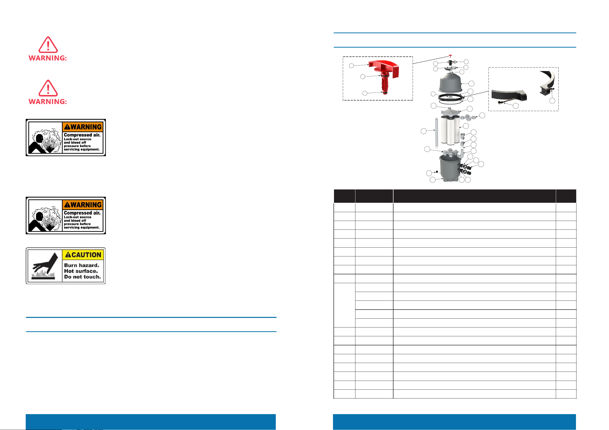
QTYQTYKey No. Part No. Description
19
20
21
22
23
24
25
26
27
28
29
30
31
111040081
550128231
E140403
111040080
112000083
112030022
E140404
111000043
550228177
E160553
107048527
107048528
107048529
107048530
107048531
914100007
914100008
914100009
914100010
914100011
550028176
O-ring d63.8×5
Outlet adaptor
Elbow assemble
O-ring d56.2×2.5
Screw 3/8in
Nut 3/8in
Ring clamp assemble
Rubber washer D526×d502x14
Bottom Body
End cap with O-ring
PVC Pipe 452mm for ICF230
PVC Pipe 508mm for ICF330
PVC Pipe 658mm for ICF430
PVC Pipe 845mm for ICF530
PVC Pipe 986mm for ICF680
Element ICF230
Element ICF330
Element ICF430
Element ICF530
Element ICF680
Element adaptor for ICF680 Only
2
1
1
4
1
1
1
1
1
1
1
1
1
1
1
4
4
4
4
8
1
As original purchaser of this equipment have purchased from Emaux Water Technology Co Ltd, through Authorized
International Distributor or Dealer, warrants its products free from defects in materials and workmanship under
normal use during warranty period. The warranty period begins on the day of purchase and extends only to the
original purchaser. It is not transferable to anyone who subsequently purchases the product from you. It excludes
all expendable parts.
During the warranty period, Emaux authorized reseller will repair or replace defective parts with new parts or, at the
option of Emaux, serviceable used parts that are equivalent or superior to new parts in performance.
8. TERMS OF THE WARRANTY
P13 TERMS OF THE WARRANTY PRODUCT