manuals.online logo
Brands
  1. Home
  2. •
  3. Brands
  4. •
  5. emaux
  6. •
  7. Water Filtration System
  8. •
  9. emaux S1000 User manual

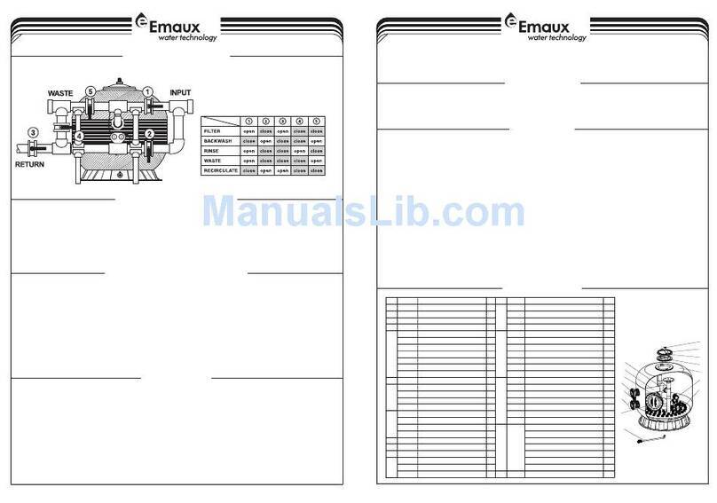
emaux S1000 User manual

1-4
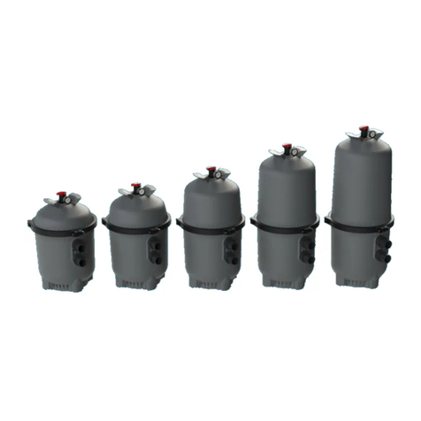
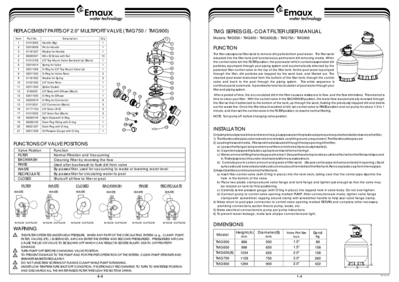
Models: S1000(C) / S1200(C)
EMF I15 030 248
名 称
版 本 编 号
规 格
比 例
颜 色
产品负责人
更改日期
更改内容
字体
版本 制图/设计
C
意万仕(中山)泳池设备有限公司
EM AU X Zh on gS ha n) Sw im mi ng Po ol E q u i p m e n t Co . , Lt d(
审核 批准
80g印尼蓝
普通印刷
2015.03
1 : 1
420X297(mm)
EMFI15030248
PANTONE Process Black C
材 料
工 艺
日 期
EMAUX S1000(C)-S1200(C) 沙缸 英文说明书
INSTALLATION
Only simple tools (screwdriver and wrenches), plus pipe sealant for plastic adapters, are required to install and
service the filter.
1) The filter should be placed on a level concrete slab, very firm ground, or equivalent. Position the filter so that
the piping connections, control valve are convenient and accessible for operation and service.
2) Loading the sand media. Filter sand media is loaded through the top opening of the filter.
a) Connect control valve to the filter using pipes with unions
b) Loosen the twelve nuts and washers and remove the filter coping.
c) We recommend filling tank approximately 1/3 way with water to provide a cushion effect when the filter
sand is poured in. This helps protect the under-drain laterals from excessive shock.
d) Carefully pour in correct amount and grade of filter sand. Sand surface should be leveled and should
come to about the middle of the filter tank.
and glues.(see the fig on page4).
FUNCTION
The filter uses special filter sand to remove dirt particles from pool water. The filter sand is loaded into the
filter tank and functions as the permanent dirt removing media.When the control valve is in the FILTER
position, the pool water which contains suspended dirt particles, is pumped through your piping system
and is automatically directed by the patented filter control valve to the top of the filter tank.As the pool
water is pumped through the filter, dirt particles are trapped by the sand bed, and filtered out. The
cleaned Pool water is returned from the bottom of the filter tank,through the control valve and back to
the pool through the piping system. This entire sequence is continuous and automatic and provides for
total recirculation of pool water through your filter and piping System.
After a period of time the accumulated dirt in the filter causes a resistance to flow, and the flow diminishes.
Thismeans it is time to clean your filter. With the control valve in the BACKWASH position, the water flow is
automatically reversed through the filter so that it is directed to the bottom of the tank, up through the sand,
flushingthe previously trapped dirt and debris out the waste line. Once the filter is back-washed of dirt, set
control valve toRINSE position and run pump for about 1/2 to 1 minute, and then to filter, to resume normal
filtering.
NOTE: Turn pump off before changing valve position.
4-4
WASTE
FILTER
BACKWASH RINSE
WASTE
RECIRCULATE
CLOSED
WASTE WASTE
WASTE WASTE WASTE
IN FLOW OUT FLOW IN FLOW OUT FLOW IN FLOW OUT FLOW
By-passes filter for circulating water to pool
Used after backwash to flush dirt from valve
Cleaning Filter by reversing the flow
By-passes filter, used for vacuuming to waste or lowering water level
CLOSED Shuts off all flow to filter or pool
RECIRCULATE
WASTE
RINSE
BACKWASH
FILTER
Valve Position
Normal Filtration and Vacuuming
Function
FUNCTIONS OF VALVE POSITIONS
THIS FILTER OPERATES UNDER HIGH PRESSURE. WHEN ANY PART OF THE CIRCULATING
PUMP, FILTER, VALVES, ETC.) IS SERVICED, AIR CAN ENTER THE SYSTEM AND BECOME PRESSURIZED .
PRESSURIZED AIR CAN CAUSE THE LID OR VALVE TO BE BLOWN OFF WHICH CAN RESULT IN SEVERE INJURY,
DEATH, OR PROPERTY DAMAGE.
TURN PUMP OFF BEFORE CHANGING VALVE POSITION.
TO PREVENT DAMAGE TO THE PUMP AND FOR PROPER OPERATION OF THE SYSTEM, CLEAN PUMP STRAINER
AND SKIMMER BASKETS REGULARLY.
DO NOT UNSCREW SCREWS OF FLANGE CLAMP WHILE PUMP IS RUNNING.
SYSTEM (e.g., CLAMP,
WARNING
GENERAL
1) Pipe tap boss provided for optional influent pressure gauge.
2) SERVICING VALVE( Stop pump,close gate valve in suction&discharge before proceeding):
a) Set handle in filter position. b) Remove cover screws. c) Lift cover and key assembly out.
TO ASSEMBLE:
1) Place valve key so that wedge opening is at TOP port (handle in Filter psn.). Flat edge of cover screw lug
should align with flat edge of body screw lug.
2) Position cover O'Ring.
3) Secure assembly to body with cover screws. Tighten cover screws evenly and alternately. Do not over-
tighten.
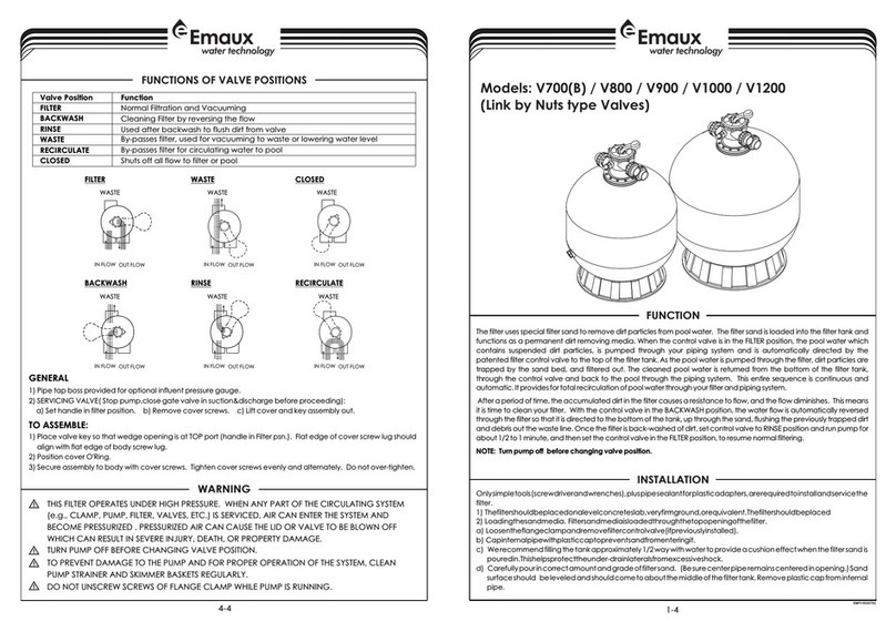
1
2
3
4
5
6
7
8
10
12
14
15
16
1718
21
22
1314151819
23
24
9
1313
11
1920
20
25
9
11
12
10
13
6
8
14
1
2
3
4
7
5
2-4
MAIN DIMENSION
REPLACEMENT PARTS OF FILTER
3-4
3) Replace filter coping. Put the twelve nuts and washers onto each of the twelve bolts, then screw all the nuts
on with wrench,ensuring that all nuts are tight.
a)
)
4) Connect pump to control valve opening marked PUMP.
5) Make return to pool pipe connection to control valve opening marked RETURN and complete other
necessary plumbing connections, suction lines to pump, waste, etc.
6) Make electrical connections to pump per pump instructions.
7) To prevent water leakage, be sure all pipe connections are tight.
Carefully screw pressure gauge (with O'ring in place) into tapped hole in the filter coping. Do not over-
tighten.

b Ensure air relief valve (with O'ring in place) is tight fit to filter coping and turn it easily.
B
A
DIMENSION TABLE
1220
Model A
High
mm
B
Diameter
mm
1410S1200(C)
10201220
S1000(C)
REPLACEMENT PARTS OF MULTIPORT VALVE
Valve Port
Size
Inch
Sand
Kg
2.5”
2.5”
860
620
Item No.Part No. Product Description Qty
1
2
3
4
5
6
7
8
9
10
11
12
13
14
15
16
17
18
19
20
21
22
23
24
25
01013003
03018008
01181027
89281204
01021129
02010228
02011022
01181002
03014025
89280806
01021128
06011032
02020053
01171159
01150180
01150181
01150180
01013147
01051243
01171158
02010043
01013142
89280104
01111048
89021303
01013143
Handle ( Big)
Pin for Ha ndle
Washer f or Handle(Whit e)
M6*33 T Scr ew with Nut
2.5"Side Mou nt Valve Standa rd L id(White)
O-Ring for 2.5" V alve Lid
O-Ring for 2.5" V alve Rotor
Washer f or Spring(Whit e)
Spring f or 2.5" Side Mount Val ve
2.5" Valv e Rotor Wit h Spider Gasket
2.5" Side Mou nt Valve Bottom B od y(White)
Oil Pres sure Gauge with O-r in g ( 40Psi)
O-Ring for 2.5"U nion
2.5" Union (White)
2.5" PVC Tube 9 0mm
2.5" Elbow Tu be
2.5" PVC Tube 2 70mm
2.5"Connec tor ( Black)
2.5"Connec tor ( white)
2.5"Union ( A/E)(wh ite)
O-Ring for U nion Adaptor
2.5" Side Mou nt Valve Plug ( White )
Sight Gl ass With O-Ring
Connec tor for Pressure Ga uge/Stopper (W hite)
Drain Pl ug with O'Ring(Whi te )
2.5"Connec tor(White)
1
1
1
12
1
1
2
1
1
1
1
1
7
2
2
1
1
2
3
5
5
2
1
2
2
3
Key No.
Part No.
Produc t Description
Qty
1
011111 00
Star-Sh aped Nut
1
2
030420 01
Bow-Sha ped Metal Bar
1
3
020111 55
O-Ring for M anhole
1
4
011610 06
Manhol e
1
5
890113 13
S1000C F ilter Tank With B as e
1
890113 14
S1200C F ilter Tank With B as e
1
6
892808 04
2.5" Side Mou nt Valve
1
7
060110 29
Oil Pres sure Gauge With O-r in g (40 psi)
1
011110 48
Connector for Press ure Gauge/Stop pe r
1
8
892801 17
Connector Plate Sid e Mount
1
9
890113 09
S1000C T op part of the inne r ta nk system
1
890113 10
S1200C Top part of the inn er t ank system
1
10
890113 11
S1000C Bottom part of the inner tank system
1
890113 12
S1200C Bottom part of the inner tank system
1
11
011100 30
Tank Sys tem Support
2
12
890113 07
S1000C A ir Vent Pipe
1
890113 08
S1200C A ir Vent Pipe
1
13
890113 19
S1000C Laterals(185mm+129mm+126mm)
8
890113 20
S1200C Laterals(233mm+129mm+126mm)
8
14
890101 07
Water Dr ain Set
1
INSTALL/START-UP OF FILTER
1) Be sure correct amount of filter media sand is in tank and that all connections have been made and are
secure.
2) Depress control valve handle and rotate to BACKWASH position. (To prevent damage to control valve
seal, always depress handle before turning.)
3) Prime and start pump according to pump instructions (be sure all suction and return lines are open),
allowing the filter tank to fill with water. Once water is flowing out of the waste line, run the pump for at
least 1 minute. The initial back-washing of the filter is recommended to remove any impurities or fine sand
particles in the sand media.
4) Turn pump off and set valve to RINSE position. Start pump and operate until water in sight glass is clear,
about 1/2 to 1 minute.Turn pump off and set valve to FILTER position and restart pump.The filter is now
operating in the normal filter mode, filtering dirt particles from the pool water.
5) Adjust pool suction and return valves to achieve desired flow. Check system and filter for water leaks and
tighten connections, bolts, nuts, as required.
6) Note the initial pressure gauge reading when the filter is clean. (It will vary from pool to pool depending
upon the pump and general piping system.) As the filter removes dirt and impurities from the pool water,
the accumulation in the filter will cause the pressure to rise and flow to diminish. When the pressure gauge
reading is 1.5 bar, higher than the initial "clean" pressure you noted, it is time to backwash the filter (see
BACKWASH under filter and control valve functions).
NOTE: During initial clean-up of the pool water it may be necessary to backwash frequently due to the unusually
heavy initial dirt load in the water.

This manual suits for next models

3

Other emaux Water Filtration System manuals

emaux NL1200 User manual

emaux

emaux NL1200 User manual

emaux V700B User manual

emaux

emaux V700B User manual

emaux SSC mini User manual

emaux

emaux SSC mini User manual

emaux EM2837 Safety guide

emaux

emaux EM2837 Safety guide

emaux EM2861 Safety guide

emaux

emaux EM2861 Safety guide

emaux GALAXY IDE Series User manual

emaux

emaux GALAXY IDE Series User manual

emaux EM2817V Series Manual

emaux

emaux EM2817V Series Manual

emaux SSCnano User manual

emaux

emaux SSCnano User manual

emaux V350 User manual

emaux

emaux V350 User manual

emaux NT-UV Series User manual

emaux

emaux NT-UV Series User manual

emaux ICF 100 User manual

emaux

emaux ICF 100 User manual

emaux SSC one User manual

emaux

emaux SSC one User manual

emaux FSCO Series User manual

emaux

emaux FSCO Series User manual

emaux TMG Series User manual

emaux

emaux TMG Series User manual

emaux CLL Series User manual

emaux

emaux CLL Series User manual

emaux MER150-100S User manual

emaux

emaux MER150-100S User manual

emaux ICF 230 User manual

emaux

emaux ICF 230 User manual

Popular Water Filtration System manuals by other brands

Eclipse Magnetics Micromag HP/80NPT operating instructions

Eclipse Magnetics

Eclipse Magnetics Micromag HP/80NPT operating instructions

Culligan US-DC1 Installation and operating instructions

Culligan

Culligan US-DC1 Installation and operating instructions

Prio Expert M400 user guide

Prio

Prio Expert M400 user guide

Sunlight Supply 738315 Setup and maintenance guide

Sunlight Supply

Sunlight Supply 738315 Setup and maintenance guide

3M 5000 Series manual

3M

3M 5000 Series manual

MAUNAWAI Wai Assembly and operating instructions

MAUNAWAI

MAUNAWAI Wai Assembly and operating instructions

Graf Garden Comfort Platin 1500 L installation manual

Graf

Graf Garden Comfort Platin 1500 L installation manual

AquaScape 99774 Instructions & maintenance

AquaScape

AquaScape 99774 Instructions & maintenance

GE 215C1044P010-3 Owner's manual and installation

GE

GE 215C1044P010-3 Owner's manual and installation

SafeShore HydroSweep Pro Installation and Operating Instrucitons

SafeShore

SafeShore HydroSweep Pro Installation and Operating Instrucitons

Clean Water Systems 7500-REV2.5 installation guide

Clean Water Systems

Clean Water Systems 7500-REV2.5 installation guide

Nikken PIMAG AQUA POUR EXPRESS Quick reference sheet

Nikken

Nikken PIMAG AQUA POUR EXPRESS Quick reference sheet

Argo-Hytos FAPC 016 manual

Argo-Hytos

Argo-Hytos FAPC 016 manual

Tecnogas DSBLUE.PL Operation manual

Tecnogas

Tecnogas DSBLUE.PL Operation manual

Rena SmartFilter 55 manual

Rena

Rena SmartFilter 55 manual

Pentair 165 Installation and user guide

Pentair

Pentair 165 Installation and user guide

Geovent W 3 instruction manual

Geovent

Geovent W 3 instruction manual

BWT PERMAQ compact 4 Fitting and operating instructions

BWT

BWT PERMAQ compact 4 Fitting and operating instructions

manuals.online logo
manuals.online logoBrands
  • About & Mission
  • Contact us
  • Privacy Policy
  • Terms and Conditions

Copyright 2025 Manuals.Online. All Rights Reserved.