B
A
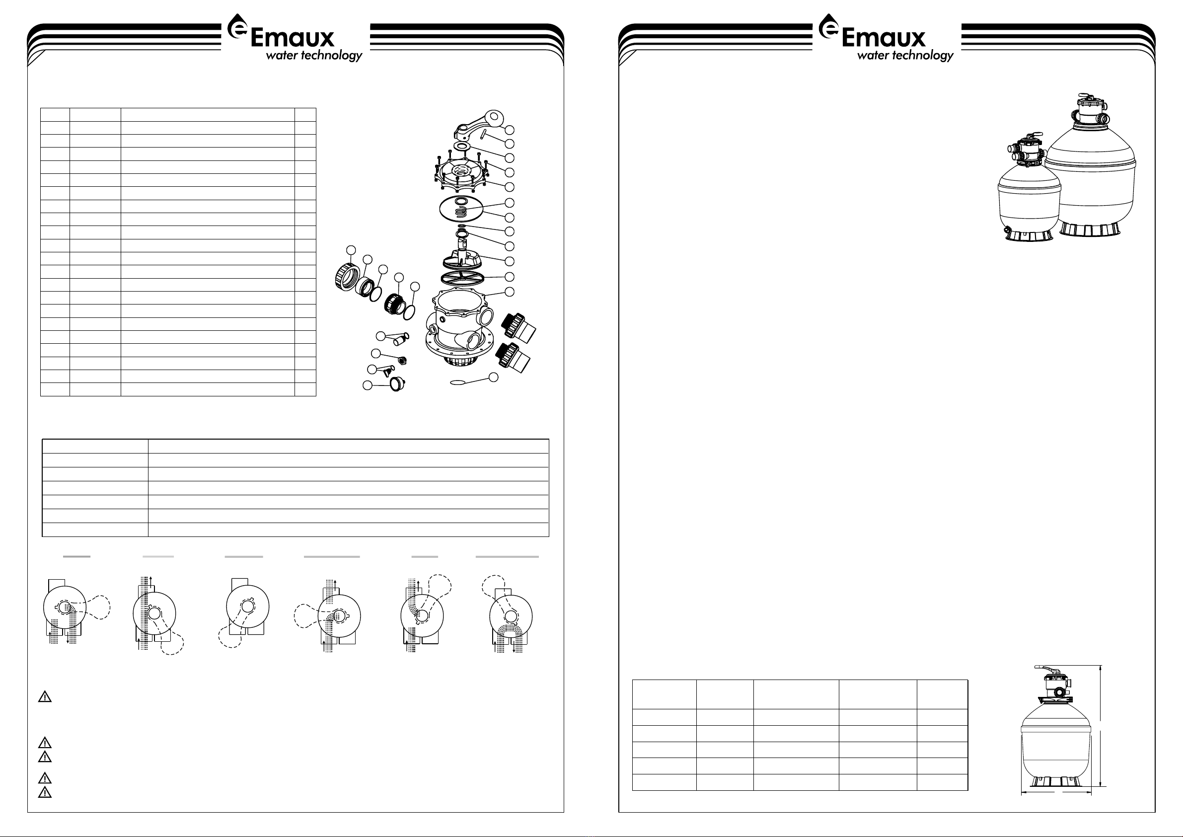
1-4
FUNCTION
INSTALLATION
Models: TMG500 / TMG650 / TMG650(B) / TMG750 / TMG900
WARNING
4-4
By-passes filter for circulating water to pool
Used after backwash to flush dirt from valve
Cleaning Filter by reversing the flow
By-passes filter, used for vacuuming to waste or lowering water level
CLOSED Shuts off all flow to filter or pool
RECIRCULATE
WASTE
RINSE
BACKWASH
FILTER
Valve Position Normal Filtration and Vacuuming
Function
FUNCTIONS OF VALVE POSITIONS
WASTE
FILTER
IN FLOW OUT FLOW
WASTE
WASTE
IN FLOW OUT FLOW
CLOSED
WASTE
IN FLOW OUT FLOW
BACKWASH
WASTE
IN FLOW OUT FLOW
RINSE
WASTE
IN FLOW OUT FLOW
RECIRCULATE
WASTE
IN FLOW OUT FLOW
Thefilterusesspecialfiltersandtoremovedirtparticlesfrompoolwater. Thefiltersand
is loaded into thefilter tank and functions as a permanent dirt removing media. When
thecontrol valveis intheFILTERposition,the pool waterwhich containssuspendeddirt
particles, is pumped through your piping system and is automatically directed by the
patented filter control valve to the top of the filter tank. As the pool water is pumped
through the filter, dirt particles are trapped by the sand bed, and filtered out. The
cleaned pool water is returned from the bottom of the filter tank, through the control
valve and back to the pool through the piping system. This entire sequence is
continuousandautomatic.Itprovidesfortotalrecirculationofpoolwaterthroughyour
filterandpipingsystem.
Aftera periodoftime,theaccumulateddirtinthefiltercausesa resistancetoflow,andtheflowdiminishes. Thismeansitis
timetocleanyourfilter. WiththecontrolvalveintheBACKWASHposition,thewaterflowisautomaticallyreversedthrough
the filter so that it is directed to the bottom of the tank, up through the sand, flushing the previously trapped dirt and debris
outthewasteline.Oncethefilterisback-washedofdirt,setcontrolvalvetoRINSEpositionandrunpumpforabout1/2to1
minute,andthensetthecontrolvalveintheFILTERposition,toresumenormalfiltering.
NOTE: Turnpumpoff beforechangingvalveposition.
Onlysimpletools(screwdriverandwrenches),pluspipesealantforplasticadapters,arerequiredtoinstallandservicethefilter.
1) Thefiltershouldbeplacedonalevelconcreteslab,veryfirmground,orequivalent.Thefiltershouldbeplaced
2) Loadingthesandmedia. Filtersandmediaisloadedthroughthetopopeningofthefilter.
a) Loosentheflangeclampandremovefiltercontrolvalve(ifpreviouslyinstalled).
b) Capinternalpipewithplasticcaptopreventsandfromenteringit.
c) Werecommendfillingthetankapproximately1/2waywithwatertoprovideacushioneffectwhenthefiltersandispoured
in.Thishelpsprotecttheunder-drainlateralsfromexcessiveshock.
d) Carefullypourincorrectamountandgradeoffiltersand. (Besurecenterpiperemainscenteredinopening.)Sand
surfaceshould beleveledandshouldcometoaboutthemiddleofthefiltertank.Removeplasticcapfrominternalpipe.
3)Assemblefiltercontrolvalveintothefiltertank.
a) Insert filter control valve (with O'ring in place) into the tank neck, taking care that the center pipe slips into the
hole in the bottom of the valve.
b) Place two plastic clamps around valve flange and tank flange and tighten just enough so that the valve may
be rotated on tank for final positioning.
c) Carefully screw pressure gauge (with O'ring in place) into tapped hole in valve body. Do not over-tighten.
d) Connect pump to control valve opening marked PUMP. After connections are made, tighten valve flange
clamps with screwdriver, tapping around clamp with screwdriver handle to help seat valve flange clamp.
4) Make return to pool pipe connection to control valve opening marked RETURN and complete other necessary
plumbing connections, suction lines to pump, waste, etc.
5) Make electrical connections to pump per pump instructions.
6) To prevent water leakage, make sure all pipe connections are tight.
THIS FILTER OPERATES UNDER HIGH PRESSURE. WHEN ANY PART OF THE CIRCULATING SYSTEM (e.g., CLAMP, PUMP,
FILTER, VALVES, ETC.) IS SERVICED, AIR CAN ENTER THE SYSTEM AND BECOME PRESSURIZED . PRESSURIZED AIR CAN
CAUSE THE LID OR VALVE TO BE BLOWN OFF WHICH CAN RESULT IN SEVERE INJURY, DEATH, OR PROPERTY
DAMAGE.
TURN PUMP OFF BEFORE CHANGING VALVE POSITION.
TO PREVENT DAMAGE TO THE PUMP AND FOR PROPER OPERATION OF THE SYSTEM, CLEAN PUMP STRAINER AND
SKIMMER BASKETS REGULARLY.
DO NOT UNSCREW SCREWS OF FLANGE CLAMP WHILE PUMP IS RUNNING.
UNDER LOW TEMPERATURE SHUT OFF CONDITION, IT IS STRONGLY RECOMMEND TO TURN TO WINTERISE POSITION
AND DISCHARGE ALL THE WATER INSIDE FILTER THROUGH THE BOTTOM DRAIN.
TMG SERIES GEL-COAT FILTER USER MANUAL
REPLACEMENT PARTS OF 2.0" MULTIPORT VALVE (TMG750 / TMG900)
DIMENSIONS
EMFI19031320
TMG500
Model
998
886
Height(A)
mm
1034
1159
1294
500
650
Diameter(B)
mm
650
750
900
Sand
kg
158
88
158
260
422
Inch
Valve Port Size
1.5"
1.5"
2.0"
2.0"
2.0"
TMG650
TMG650(B)
TMG750
TMG900
2.0" Top Mount Valve Standard Lid (Black)
O-Ring for 2.0" Top Mount Valve Lid
2.0" Body with Diffuser (Black)
Drain Plug Fitting with O-ring
Oil Pressure Gauge with O-ring
1
2
3
4
5
6
7
8
9
10
11
12
13
14
15
14
16
17
18
19
20
21


