manuals.online logo
Brands
  1. Home
  2. •
  3. Brands
  4. •
  5. Emerson
  6. •
  7. Controllers
  8. •
  9. Emerson Fisher 67C Series User manual

Emerson Fisher 67C Series User manual

44 ซ.บรมราชชนนี 70 ถ.บรมราชชนนี ศาลาธรรมสพน์ ทวีวัฒนา กทม. 10170.
website: https://www.add-furnace.com/ โทร: 02-888-3472
Line ID: @add11 e-mail: [email protected]
64and67CSeriesRegulatorsInstructionManual
! WARNING
Failure to follow these instructions or to properly
install and maintain this equipment could result in
an explosion and/or fire causing property damage
and personal injury or death.
Fisher® equipment must be installed, operated,
and maintained in accordance with federal,
state, and local codes and Emerson Process
Management Regulator Technologies, Inc.
instructions. The installation in most states must
also comply with NFPA No. 54 and 58 standards.
Only personnel trained in the proper procedures,
codes, standards, and regulations of the
LP-Gas industry should install and service
this equipment.
THINGS TO TELL THE GAS CUSTOMER:
1. Point out the regulator’s vent to the customer (or vent
assembly or vent tube), and stress that this opening must
remain unobstructed at all times. Tellthe customer to be
sure to check the vent opening after a freezing rain, sleet
storm,or snow to make sure ice has notformedin the vent.
2. Show the customer the shutoff valve on the container.The
customer should close this valve immediately if gas is
smelled,appliance pilot lights fail to stayon or appearhigher
than usual, or any other abnormal situationoccurs.
W8810
P1027
67C SERIES REGULATORS
64 SERIES REGULATOR
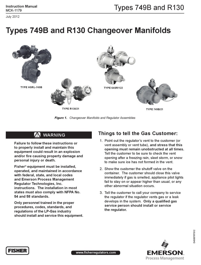
Figure 1. 64 and 67C Series Regulators
3. Tellthe customer to call your company to service the
regulatorif the regulator vents gas or a leak develops in the
system. Only a qualified gas service person should
install or service the regulator.
Introduction
Scope of the Manual
This manual provides instructions and maintenance for the
following high-pressure regulators: Types 64, 64KB, 64SR,
67CW, 67CH, 67CD, and 67CN regulators.
Description
The 64 and 67C Series direct-operated regulators (Figure1) are
designed for high-pressure(pounds per square inch) service and can
be used on either vapor applications in LP-Gas, Natural Gas, and Air
or liquid LP-Gas applications. Depending upon type, outlet pressure
ranges from 3 to 135 psig (0,21 to 9,3 bar). Type 64SR can be used
as a First Stage LP-Gas regulator–reducing tank pressure to
10 psig (0,69 bar) for a Second Stage regulator.Type64KB is the
only regulator in thisseries suitable for anhydrousammonia (NH3)
service. The regulators are normally painted red.
CAUTION
Do not use the 67C, 64, or 64SR Series regulators
in anhydrous ammonia (NH3) service. They
contain brass materials that are not compatible
with anhydrous ammonia (NH3).
Table 1. Available Configurations
TYPE
DESCRIPTION
64
Basic regulator with four spring ranges from 3 to 100 psig
(0,21 to 6,9 bar).
64SR
Internal relief version with three spring ranges from 3 to 35 psig
(0,21 to 2,4 bar).
64KB
For use with anhydrous ammonia (NH3) with handwheel
adjustment and five spring ranges from 3 to 100 psig
(0,21 to 6,9 bar). Includes a special diaphragm protector.
67CW
Basic regulator with wrench adjustment and four spring ranges
from 3 to 135 psig (0,21 to 9,3 bar); no relief.
67CH
Basic regulator with handwheel adjustment.
67CD
Basic regulator with dial cap adjustment.
67CN
Basic regulator, factory set with no field adjustment.
www.fisherregulators.com/lp
D450128T012
44 ซ.บรมราชชนนี 70 ถ.บรมราชชนนี ศาลาธรรมสพน์ ทวีวัฒนา กทม. 10170.
website: https://www.add-furnace.com/ โทร: 02-888-3472
Line ID: @add11 e-mail: [email protected]
Specifications
Body Sizes, Inlet and Outlet Connection Style
64 Series: 1/2-inch NPT, inlet and outlet
67C Series: 1/4-inch NPT, inlet and outlet
Side Outlet Connection Style (Plugged)
1/4-inch NPT; pressure gauge can be installed
Maximum Inlet Pressure (Body Rating)(1)
250 psig (17,2 bar)
Maximum Emergency Outlet Pressure(1)
64 Series: 220 psig (15,2 bar)
67C Series: 50 psig (3,4 bar) over outletpressure
Pressure Registration
Internal
Wide-Open Flow Coefficients
64 Series: Cg: 35.6; Cv: 0.36; C1: 39.0
67C Series: Cg: 11.7; Cv: 0.36; C1: 32.2
Regulator Temperature Capabilities
64 Series: -20°to 150°F (-29°to 66°C)
67C Series: -20°to 180°F (-29°to 82°C)
Spring Case Vent Location
64 Series:
1/4-inch NPT screened over side outlet tap
67C Series:
Aligned with inlet, other positions optional
Approximate Unit Weights
64 Series: 2.25 pounds (1 kg)
67C Series: 1 pound (0,5 kg)
1. The pressure/temperature limits in this Instruction Manual or any applicable standard limitation should not be exceeded.
Table 2. Outlet Pressure Ranges
SPRING RANGE,
PSIG (bar)(1)
TYPE NUMBER AND FACTORY SETPOINT, PSIG (bar)
67CW, 67CD, and 67CH
67CN
64SR
64 and 64KB
3 to 15 (0,21 to 1,0)
- - - -
- - - -
10 (0,69)
10 (0,69)
3 to 20 (0,21 to 1,4)
15 (1,0)
- - - -
15 (1,0)
15 (1,0) 64KB only
5 to 35 (0,34 to 2,4)
20 (1,4)
10 (0,69); 15 (1,0); or 20 (1,4)
20 (1,4)
20 (1,4)
20 to 50 (1,4 to 3,4)
40 (2,8) 67CD only
- - - -
- - - -
- - - -
30 to 60 (2,1 to 4,1)
40 (2,8) 67W and 67CH only
- - - -
- - - -
40 (2,8)
35 to 100 (2,4 to 6,9)
50 (3,4) 67CD only
- - - -
- - - -
50 (3,4)
35 to 135 (2,4 to 9,3)
50 (3,4) 67W and 67CH only
- - - -
- - - -
- - - -
1. Allspringscanbebackedoffto0psig(0bar)exceptType67CN. However,forthehighestcapacityandmostaccuratecontrol,usethelowestspringthatcanbeadjustedtotherequiredsetpoint.
Specifications
Some general 64 and 67C Series ratings and other specifications
are given on Specifications section. A spring case label gives the
spring range for the regulator as it comes from the factory.
Installation
! WARNING
Failure to follow these instructions and warnings
could result in personal injury or property damage.
All vents should be kept open to permit free flow
of air into and out of the regulator.
Protect openings against the entrance of rain,
snow, ice formation, paint, mud, insects, or any
other foreign material that could plug the vent or
vent lines.
LP-Gas may discharge to the atmosphere through
the vent of a Type 64SR. The internal relief valve
of the Type64SR regulator does not provide
full overpressure protection, but is designed for
minor seat leakage only. An obstructed vent
which limits air or gas flow cancause abnormally
high outlet pressure. A vent line to a remote,
safe location outdoors is required on permanent
indoor installations or on installations where
there can be a hazardous accumulation ofgas.
Never use a 64 or 67C Series (pounds to pounds)
regulator on low-pressure (inches of water
column) service.
1. Regulator operation within ratings does not preclude the
possibilityof damage from debris in the lines or from external
sources. Regulators should be inspected for damage
periodically and after any overpressure condition.
2. Only personnel qualified through training and experience
should install, operate, and maintain a regulator. Make sure
that there is no damage to or foreign material in the regulator.
Also, ensure that all tubing and piping is free ofdebris.
3. Install the regulator so that flow is fromthe IN to theOUT
connection as marked on the regulator body.
4. Protecttheregulatorfromvehiculartrafficordamagefrom
other external sources.
5. Install the regulator high enough above ground level, at least
18-inches (457 mm), so that rain splatter cannot freeze in the
vent.Do notinstall the regulator in a location where there can
be excessive water accumulation or ice formation, such as
directly beneath a downspout,gutter, or roof line or a building.
6. A regulator installed outdoors without a protective hood must
have its vent pointed vertically down to prevent clogging and
moisture accumulation. A clogged spring case vent hole may
cause the regulator to function improperly. Tokeepthis
vent hole from being plugged (and to keep the spring case
2
44 ซ.บรมราชชนนี 70 ถ.บรมราชชนนี ศาลาธรรมสพน์ ทวีวัฒนา กทม. 10170.
website: https://www.add-furnace.com/ โทร: 02-888-3472
Line ID: @add11 e-mail: [email protected]
from collecting moisture, corrosive chemicals, or other foreign
material) orient the vent to the lowest possible point on the
spring case or point it verticallydown, or install the regulator
under a protective cover so that it is protected from the
elements. Inspect the vent hole regularly to make sure it is not
plugged. Spring case vent hole orientation may bechanged
by rotating the spring case with respect to the body. A
SHUTOFF VALVE,
PLUG COCK, ETC.
1/4-inch threaded NPT spring case vent may be remotely
vented by installing obstruction-free tubing or piping into the
vent. Protect the remote vent by installing a screened vent
cap on the remote end of the vent pipe.
7. For use in regulator shutdown, install upstream block and
vent valves and downstream block and vent valves (if
required), or provide some other suitable means of properly
venting the regulator inlet and outlet pressures. Install a
pressure gauge to monitor instruments onstartup.
8. Applya good grade of pipe compound to the male pipe threads
before making connections, making sure not to get the pipe
compound inside the regulator.
9. Install tubing fitting or pipinginto the NPT inlet andoutlet
connections on the body.
10. The second 1/4-inch threaded NPT side outlet can be used
for a gauge or other use. If not used, it must beplugged.
11. On liquid service, it is recommended that shutoff valves
be installed on the inlet side of the regulators. Figure 2
shows a typical installation using the Type 64SR. If other
regulator models are used, an external relief valveis
required downstream of the regulator and before any shutoff
valve. Installations with shutoffs downstream of the regulator
can trap liquid between the regulator and the shutoff. The
trapped liquid can vaporize, opening the internal or external
relief valve. On installations where it is impossible to install
the regulator without using shutoffs between the regulator
and the burner,either install the regulator in a safelocation or
run a vent line from the Type 64SR vent or the discharge
point of the relief valve to a safe location so that any
discharge through the relief valve will not create ahazard.
Overpressure Protection
! WARNING
Personal injury or system damage may result if
these regulators are installed without appropriate
overpressure protection. If maximum inlet
pressure to the 64 and 67C Series exceeds
maximum pressure ratings of the downstream
equipment or exceeds maximum allowable outlet
pressure of the 64 and 67C Series, then additional
overpressure protection is required. Outlet
pressures greater than Maximum Emergency
Outlet Pressure limits may cause damage to
regulator parts, leaks in the regulator, or personal
injury due to bursting of pressure-containing
parts or explosion of accumulatedgas.
If these regulators are exposed to an
overpressure condition, they must be inspected
for damage that may have occurred.
ACCEPTABLE WITH VENT LOCATED OR PIPED TO
SAFE LOCATION
Figure 2. Type 64SR on Liquid Service Requires Care with
Downstream Restrictions
Large volumes of gas may discharge through
the Type 64SR regulator vent during internal
relief valve operation, which can result in fire or
explosion from accumulated gas.
Arelief valveisrequireddownstreamofalltheseregulator
to provide overpressure protection to prevent damage to
downstreamequipmentand systemsorwhen used inliquid
service. The Type 64SR has an internal relief valve that opens
when downstream pressure reaches approximately 125% to
250% of the setpoint. Gas discharge is through the regulator
vent. The Type 64SR gives overpressure protection against
excessivebuildupresultingfrom seat leakagedueto wornparts
or chips of foreign material on the orifice. Additional external
reliefvalvesmayberequiredto preventoverpressuredamageto
downstreamequipmentorsystems.
Startup and Adjustment
1. With proper installation completed and downstream equipment
properly adjusted, slowly open the upstream and downstream
shutoff valve (when used) while using pressure gauges to
monitor pressure.
! WARNING
To avoid personal injury, property damage,
or equipment damage caused by bursting
ofpressure-containingpartsorexplosionof
accumulatedgas,neveradjustthecontrol spring
to produce an outlet pressure higher than the
upper limit of the outlet pressure range for that
particular spring. If the desired outlet pressure
is not within the range of the control spring,
install a spring of the proper range according to
theDiaphragmPartsMaintenanceprocedure.
2. If outlet pressure adjustment is necessary, monitor outlet
pressure with a gauge during the adjustment procedure. The
regulator, except for the Type 67CN which is notfield
3
RECOMMENDED
44 ซ.บรมราชชนนี 70 ถ.บรมราชชนนี ศาลาธรรมสพน์ ทวีวัฒนา กทม. 10170.
website: https://www.add-furnace.com/ โทร: 02-888-3472
Line ID: @add11 e-mail: [email protected]
adjustable, is adjusted by loosening the locknut, if used, and
turning the adjusting screw or handwheel clockwise to increase
or counterclockwise to decrease the outlet pressure setting.
Re-tighten the locknut to maintain the adjustment position.
Shutdown
First, close the nearest upstream block valve and then close
the nearest downstream block valve (when used). Next, open
the downstreamvent valve. Sincethe regulator remains open
in response to the decreasing downstream pressure, pressure
between the closed block valves will be released through the open
vent valve.
Maintenance
! WARNING
To avoid personal injury or equipment damage,
do not attempt any maintenance or disassembly
without first isolating the regulator from system
pressure and relieving all internal pressure.
Regulators that have been disassembled for
repair must be tested for proper operation
before being returned to service. Only parts
manufactured by Emerson Process Management
Regulator Technologies, Inc. should be used for
repairing Fisher® regulators. Relight pilot lights
according to normal startupprocedures.
Due to normal wear or damage that may occur
from external sources, these regulators must
be inspected and maintained periodically. The
frequency of inspection and replacement of
the regulators depends upon the severity of
service conditions or the requirements oflocal,
state, and federal regulations. Even under ideal
conditions, these regulators should be replaced
after 15 years from date of manufacture or sooner
should inspection reveal the need.
Failure to do the following could result in personal injury or
property damage. Visually inspect the regulator each time a gas
delivery is made for:
1. Improperinstallation;
2. Plugged or frozen vent;
3. Wrong regulator or no regulator in thesystem;
4. Internal or external corrosion;
5. Age of the regulator;
6. Any other condition that could cause the uncontrolled
escape ofgas.
Make sure the regulator vent, vent assembly, or vent tube does
not become plugged by mud, insects, ice, snow, paint, etc. The
vent screen aids in keeping the vent from becoming plugged,
and the screen should be clean and properly installed.
Replace any regulators that have had water in their spring case
or show evidence of external or internal corrosion. Checking for
internal corrosion may require complete removal of the adjusting
screw and shutdown of the gas system. Closely examine
regulators directly connected to the container valve by means of
a solid POL adaptor (horizontal mounting) for signs of corrosion.
Correct any improper installations.
Older regulators are more likely to catastrophically fail because
of worn or corroded parts. Replace regulators over 15 years
of age; other service or environmental conditions may dictate
replacement of the regulator before it becomes 15 years old,
refer to Fisher Bulletin LP-32.
Regulator Repair
Regulators that have been disassembled for repair must be
tested for proper operation before being returned to service.
Only parts manufactured by Emerson Process Management
Regulator Technologies, Inc. should be used to repair Fisher
regulators. Be sure to give the complete type number of the
regulator when corresponding with the factory.

Other manuals for Fisher 67C Series

2

This manual suits for next models

7

Other Emerson Controllers manuals

Emerson Liebert OpenComms EM User manual

Emerson

Emerson Liebert OpenComms EM User manual

Emerson uerdant VX Series User manual

Emerson

Emerson uerdant VX Series User manual

Emerson Fisher easy-Drive 200R User manual

Emerson

Emerson Fisher easy-Drive 200R User manual

Emerson SH Series User manual

Emerson

Emerson SH Series User manual

Emerson Fisher 1052 User guide

Emerson

Emerson Fisher 1052 User guide

Emerson Fisher 299H User manual

Emerson

Emerson Fisher 299H User manual

Emerson Fincor 2330MKII Series Technical Document

Emerson

Emerson Fincor 2330MKII Series Technical Document

Emerson Dixell iPro Master IPM500D Wiring diagram

Emerson

Emerson Dixell iPro Master IPM500D Wiring diagram

Emerson Unidrive M100 Use and maintenance manual

Emerson

Emerson Unidrive M100 Use and maintenance manual

Emerson Fisher 656 User manual

Emerson

Emerson Fisher 656 User manual

Emerson Control Link User manual

Emerson

Emerson Control Link User manual

Emerson Bettis RPE Series User manual

Emerson

Emerson Bettis RPE Series User manual

Emerson FISHER 67 User manual

Emerson

Emerson FISHER 67 User manual

Emerson numatics g3 series User manual

Emerson

Emerson numatics g3 series User manual

Emerson FXMP25 User manual

Emerson

Emerson FXMP25 User manual

Emerson Fisher 67CS User manual

Emerson

Emerson Fisher 67CS User manual

Emerson Tarantini MN Quick guide

Emerson

Emerson Tarantini MN Quick guide

Emerson FISHER 670 Series User manual

Emerson

Emerson FISHER 670 Series User manual

Emerson Fisher Y600A Series User manual

Emerson

Emerson Fisher Y600A Series User manual

Emerson Leroy Somer R450 Instruction Manual

Emerson

Emerson Leroy Somer R450 Instruction Manual

Emerson Keystone EPI2 63 User manual

Emerson

Emerson Keystone EPI2 63 User manual

Emerson Fisher HSR Series User manual

Emerson

Emerson Fisher HSR Series User manual

Emerson Fisher 67D Series User manual

Emerson

Emerson Fisher 67D Series User manual

Emerson HVAC Drive H300 User manual

Emerson

Emerson HVAC Drive H300 User manual

Popular Controllers manuals by other brands

Monicon GTR-85 owner's manual

Monicon

Monicon GTR-85 owner's manual

Lenze c250-S Mounting instructions

Lenze

Lenze c250-S Mounting instructions

Precision Digital Corporation Helios PD2-6310 instruction manual

Precision Digital Corporation

Precision Digital Corporation Helios PD2-6310 instruction manual

Autonics SPR Series User Manual for Communication

Autonics

Autonics SPR Series User Manual for Communication

SOMFY Control Box 3S io Installtion Instructions

SOMFY

SOMFY Control Box 3S io Installtion Instructions

Maxon 297115-01 instructions

Maxon

Maxon 297115-01 instructions

Coremorrow E81.A1K Series user manual

Coremorrow

Coremorrow E81.A1K Series user manual

Siemens SINUMERIK 840D sl operating manual

Siemens

Siemens SINUMERIK 840D sl operating manual

Siemens Simatic S7-300 Getting started

Siemens

Siemens Simatic S7-300 Getting started

Belanger CUBE owner's manual

Belanger

Belanger CUBE owner's manual

Garmin GRID 20 installation instructions

Garmin

Garmin GRID 20 installation instructions

LOVATO ELECTRIC ATL500 instruction manual

LOVATO ELECTRIC

LOVATO ELECTRIC ATL500 instruction manual

QLT MDR45 installation instructions

QLT

QLT MDR45 installation instructions

Aaeon AEC-6872 manual

Aaeon

Aaeon AEC-6872 manual

Sigur E510 manual

Sigur

Sigur E510 manual

Tense DT-36EM manual

Tense

Tense DT-36EM manual

Honeywell Electronic Aquastat L7148F manual

Honeywell

Honeywell Electronic Aquastat L7148F manual

Rain s-dial smart manual

Rain

Rain s-dial smart manual

manuals.online logo
manuals.online logoBrands
  • About & Mission
  • Contact us
  • Privacy Policy
  • Terms and Conditions

Copyright 2025 Manuals.Online. All Rights Reserved.