Remote Keypad User Guide 9
Issue 1 www.controltechniques.com
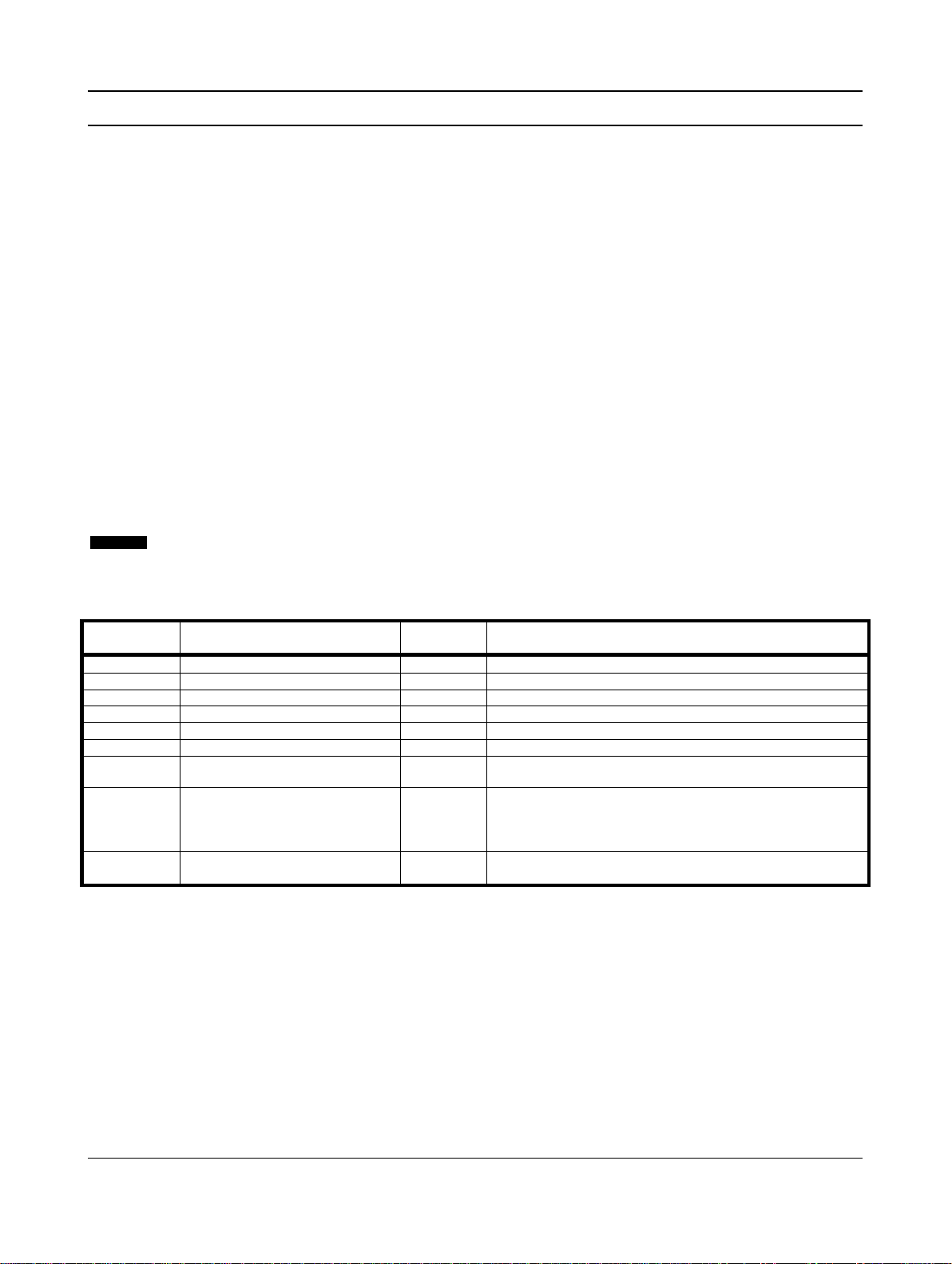
5. Troubleshooting
Table 5-1 General faults
Check that correct voltage is present at terminals 1, 2.
LED flashing
Soft starter in restart delay mode
Wait for the restart delay (programmed in the soft starter)
to elapse.
Four dashes on display and
RS485 LED flashing The Remote Keypad has detected a
loss of communication on the RS485
link to the soft starter
Verify and solve the cause for loss of communication.
If communication is restored before the soft starter trips,
the display will return to active status and the RS485 LED
will illuminate. If communication is restored after the soft
starter has tripped, the display will indicate the trip code.
Use the Reset button to reset the soft starter fault.
Incorrect or no 4-20 mA analog output
signal
Check the correct voltage is present at terminals 1, 2.
Check that correct polarity is used at terminals B10, B11.
Check that the Motor FLC, Analog Output 4 mA Offset and
÷
10 parameters are set correctly.
The motor cannot be started Check that control voltage is connected to the starter.
•If connected to a Digistart CS, check that terminals
CSL-DI2 on the starter are linked.
Pr 8on the Remote Keypad must be set to 0 or 1.
6. Specifications
Enclosure
Front Panel Height ............................................................................................................................................................... 120 mm
Front Panel Width ................................................................................................................................................................ 120 mm
Inside Panel Depth (when mounted).............................................................................................................................. 30 mm (max)
Panel Cutout ............................................................................................................................................................................92 mm2
Weight....................................................................................................................................................................................... 450 g
Power Suply
Voltage..................................................................................................................................................... 18 - 30 Vdc/Vac (50/60 Hz)
Consumption ........................................................................................................................................ 100 mA (max - steady state)
Connection (Terminals 1, 2) ................................................................................................. 2 pole spring clamp connector terminals
RS485 serial network port (optional)
RS485 Network Interface .......................................................................................... AP ASCII or Modbus RTU protocol (selectable)
Connection (Terminals B6, B7, B8) ...................................................................................... 3 pole spring clamp connector terminals
RS485 serial starter port (soft starter connection)
RS485 Soft Starter Interface............................................................................................................... AP ASCII protocol as standard
Connection (Terminals B1, B2, B3) ...................................................................................... 3 pole spring clamp connector terminals
Analog output
Motor Current Monitoring Interface....................................................................................................... 4-20 mA (max burden 200 Ω)
Connection (Terminals B10, B11)......................................................................................... 2 pole spring clamp connector terminals
Sundry
Enclosure Rating..................................................................................................... IP54 or NEMA 12 when correctly panel mounted
Pollution Degree .................................................................................................................................................. Pollution Degree 3
Operating Temperature .............................................................................................................................................. - 5 oC / + 60 oC
Relative Humidity ............................................................................................................................ 5 to 95% (max non-condensing)
This product has been designed as Class A equipment. Use of this product in domestic environments may cause radio interference, in
which case the user may be required to employ additional mitigation methods.
Approvals
CE ............................................................................................................................................................................IEC 60947-4-2
UL and C-UL .......................................................................................................................................................................... UL 508
C............................................................................................................................................................................ IEC 60947-4-2