manuals.online logo
Brands
  1. Home
  2. •
  3. Brands
  4. •
  5. Emerson
  6. •
  7. Monitor
  8. •
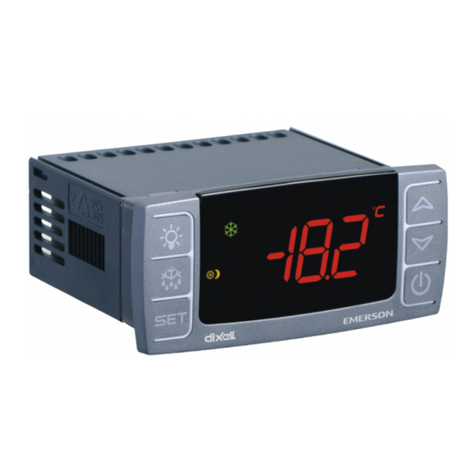
  9. Emerson ECD-002 User manual

Emerson ECD-002 User manual

ECD__65133__R03.doc replaces Rev.: 01 1 / 5 PCN 862 892 01.02.2009
ECD Anzeigeeinheit
Montageanleitung
D
Die ECD Anzeigeeinheit wird gemeinsam mit den
Controllern der Baureihen EC3 von Emerson
eingesetzt, siehe Tabelle:
Typ EC3-Controller
ECD-000
EC3-612/611, EC3-622/621, EC3-
642/641,
EC3-672/671, EC3-752/751, EC3-
812/811,
EC3-922/921
ECD-001
EC3-332/-331
ECD-002
EC3-X33/-X32, EC3-D72/-D73
!
Sicherheitshinweise:
•
Die Anzeigeeinheit kann bei Anschluß an andere
als die oben spezifizierten Controller beschädigt
werden.
•
Halten Sie die Temperaturen innerhalb der
vorgeschriebenen Grenzen.
Technische Daten
Versorgungs
spannung von EC3 über das Anschlußkabel
Anzeige 2½-stellige, rote LED-Anzeige mit
Dezimalpunkt
LED
Indikatoren bis zu 7 Indikatoren, siehe EC3
Controller Anleitung
Temperatur 0 ... +60°C (Betrieb),
-20 ... +65°C (Lagerung)
Luftfeuchte 0 ... 80% r.h. nicht kondensierend
Schutzart IP65 (bei Einbau in Schalttafel mit
Dichtung)
Anschluß-
kabel ECC-N10 (1,0m), ECC-N30 (3,0m)
ECC-N50 (5,0m) oder CAT5 Kabel mit
RJ45 Steckern
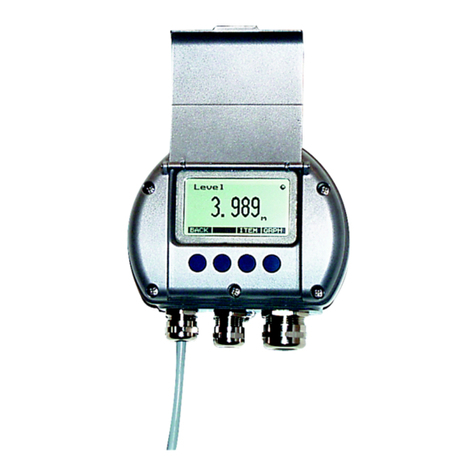
Montage
Die Anzeigeeinheit ECD kann in Frontplatten mit
einem Ausschnitt von 71 x 29mm montiert werden,
siehe Abmessungen oben.
Anzeigeeinheit vorsichtig mit eingefahrenen Halter-
ungen in den Frontplattenausschnitt einschieben.
Beiliegenden Imbusschlüssel in die Löcher auf der
Frontseite einstecken und im Uhrzeigersinn drehen.
Die Halterungen treten aus dem Gehäuse hervor und
bewegen sich in Richtung Frontplatte.
Imbussschraube weiterdrehen, bis die Halterung die
Frontplatte leicht berührt. Dann auch die zweite
Halterung in diese Position bringen.
Erst jetzt beide Seiten gleichmäßig anziehen, bis die
Anzeige festsitzt. Achtung: Halterung vorsichtig
anziehen, ansonsten droht Bruchgefahr.
Verdrahtung
ECD mit EC3 über das Anschlusskabel ECC-Nxx
oder sonstigem Standard CAT5-Kabel mit RJ45
Steckern verbinden.
Anzeige
ECD zeigt einen Messwert des angeschlossenen EC3
Controllers permanent an. Mit der SEL-Taste können
temporär andere Messwerte angezeigt werden. Wird
ca 2 Minuten keine Taste betätigt erscheint wieder die
Standardanzeige.
Bei einem Fehler blinkt die Anzeige, Fehlercode und
Messwert werden abwechselnd angezeigt.
Informationen über die angezeigten Messwerte und
die Fehlercodes sind der Betriebsanleitung des
angeschlossenen Controllers zu entnehmen.
Parametereinstellung
Die Parametereinstellung ist aus Sicherheitsgründen
passwortgeschützt. Die Eingabe des Passwortes und
die Veränderung der Parameter ist in der jeweiligen
EC3 Betriebsanleitung ausführlich beschrieben.
Die Tastenfunktionen können auch mit einer
Infrarotfernbedienung (Option) aktiviert werden.
Abmessungen
ECD Display Unit
Mounting Instructions
GB
The ECD Display Unit is for use with EC3-Series
controllers from Emerson, see table:
Type EC3-Controller
ECD-000
EC3-612/611, EC3-622/621, EC3-
642/641,
EC3-672/671, EC3-752/751, EC3-
812/811,
EC3-922/921
ECD-001
EC3-332/-331
ECD-002
EC3-X33/-X32, EC3-D72/-D73
!
Safety instructions:
•
Display unit can be damaged, if used with others
than the above specified controllers.
•
Keep the temperatures within the specified
limits.
Technical data
Power
supply From EC3 via connecting cable
Display 2½-digit red LED with decimal point
LED
Indicators up to 7 Indicators, see EC3 Controller
Instructions
Temperature
0 ... +60°C (operating),
-20 ... +65°C (storage)
Humidity 0 ... 80% r.h. non condensing
Protection
class IP65 (front protection with gasket)
Connecting
cable ECC-N10 (1,0m), ECC-N30 (3,0m)
ECC-N50 (5,0m) or CAT5 Cable with
RJ45 Plugs
Marking
Mounting
The ECD-001 can be mounted in panels with a 71 x
29 mm cutout. See dimensional drawing above for
space requirements.
Push controller into panel cutout.
Insert allen key into front panel holes and turn
clockwise. Mounting lugs will turn and gradually
move towards panel.
Turn allen key until mounting lug barely touches
panel. Then move other mounting lug to the same
position.
Tighten both sides very carefully until controller is
secured. Do not over tighten as mounting lugs will
break easily.
Wiring
Use connecting cable ECC-Nxx or any other standard
CAT5-Cable with RJ45 plugs to connect ECD with
EC3.
Display
ECD is showing one measured value of the connected
EC3 controller. Press the SEL button to scroll through
all possible displayable data. After approximately 2
Minutes the display will again display the default
value.
In case of an alarm the display is blinking. The alarm
code and the measured value are displayed
alternatively.
Consult the controllers operating instructions for a
detailed description of all Alarm Codes.
Parameter Setting
The parameter setting is password protected.
Password entry and parameter modification is
described in the respective EC3 controller operating
instructions.
All keys can be alternatively operated with the
(optional) Infrared remote control.
Dimensions
See figure above
ECD__65133__R03.doc replaces Rev.: 02 2 / 5 PCN 862 892 27.07.2009
Дисплей ECD
Инструкция по эксплуатации
RUS
Дисплей ECD предназначен для использования с
контроллерами серии EC3 от Emerson:
Модель Контроллер EC3
ECD-000
EC3-612/611, EC3-622/621, EC3-
642/641,
EC3-672/671, EC3-752/751, EC3-
812/811,
EC3-922/921
ECD-001
EC3-332/-331
ECD-002
EC3-X33/-X32, ЕС3-D72/ -D73
!
Инструкция по безопасности:
•
Дисплей можно повредить, если использовать
сдругими контроллерами.
•
Соблюдайте температурный режим
использования.
Те нические арактеристики
Питание От контроллера EC3 по соед.кабелю
Дисплей 2½-цифровой сдесятичной точкой
Индикаторы
До 7 индикаторов (см.инструкцию к
контроллерам EC3)
емпература 0 ... +60°C (рабочая),
-20 ... +65°C (хранение)
Влажность 0 ... 80% относит, без конденсации
Класс защиты
IP65 (сфронтальной поверхности с
прокладкой)
Маркировка
Соединитель
ный кабель ECC-N10 (1,0м), ECC-N30 (3,0м)
ECC-N50 (5,0м) или CAT5 с
разъемами RJ45
Размеры
М
онтаж
Дисплей ECD может быть установлен впанель с
отверстием 71 x 29мм.
Установите дисплей вотверстие панели.
Вставьте ключ вотверстие на лицевой панели
дисплея ивращайте по часовой стрелке.
Монтажные кронштейны будут двигаться к
панели.
Поворачивайте ключ до тех пор, пока кронштейн
не коснется панели. Затем установите второй
кронштейн. Осторожно закрепите дисплей. Не
перетягивайте кронштейны, их можно легко
повредить.
Электрические подключения
Используйте соединительный кабель ECC-Nxx
или CAT5 сразъемами RJ45 для соединения с
контроллером EC3.
Показания
Дисплей ECD показывает один из параметров
контроллера ЕС3. Нажмите кнопку «SEL» для
просмотра параметров. Если не предпринимать
никаких действий, то приблизительно через 2
минуты дисплей вернется кпараметру по
умолчанию.
Во время аварии дисплей начинает мигать.
Попеременно появляются код аварии и
измеряемый параметр.
Смотрите инструкции по эксплуатации
контроллеров для ознакомления саварийными
кодами.
Настройка параметров
Функция настройки параметров защищена
паролем. Пароль икоды параметров находятся в
инструкциях по эксплуатации контроллеров ЕС3.
Для настройки также можно использовать пульт
ДУ.
ECD
ディスプレイユニット
ディスプレイユニットディスプレイユニット
ディスプレイユニット
取扱説明書
取扱説明書取扱説明書
取扱説明書
JPN
ECDディスプレイユニットはEC3-
シリーズのコントローラです。
タイプ
タイプタイプ
タイプ
EC3
EC3EC3
EC3
コントローラ
コントローラコントローラ
コントローラ
ECD-000 EC3-612/611, EC3-622/621, EC3-
642/641, EC3-672/671, EC3-752/751,
EC3-812/811, EC3-922/921
ECD-001 EC3-332/-331
ECD-002 EC3-X33/-X32, EC3-D72/-D73
!
安全に関する注意
安全に関する注意安全に関する注意
安全に関する注意
•
上記のコントローラ以外にディスプレイユニッ
上記のコントローラ以外にディスプレイユニッ上記のコントローラ以外にディスプレイユニッ
上記のコントローラ以外にディスプレイユニッ
トを使用した場合、壊れる可能性があります。
トを使用した場合、壊れる可能性があります。トを使用した場合、壊れる可能性があります。
トを使用した場合、壊れる可能性があります。
•
温度は規定の範囲でご使用下さい。
温度は規定の範囲でご使用下さい。温度は規定の範囲でご使用下さい。
温度は規定の範囲でご使用下さい。
テクニカルデータ
テクニカルデータテクニカルデータ
テクニカルデータ
電源 EC3からの接続ケーブルで
表示 小数点機能付き2½-桁赤色LED
LED 表示 7種までの表示、EC3コントローラ
の取説参照
温度 0 ... +60°C (作動時)、
-20 ... +65°C (保管時)
湿度 相愛湿度0 ... 80% 非凝縮
保護クラス IP65 (ガスケット使)
接続ケーブル
ECC-N10 (1,0m), ECC-N30 (3,0m)
ECC-N50 (5,0m)
は、RJ45プラグ付のCAT5ケーブル
取付け
取付け取付け
取付け
ECD-001は、パネル上の71 x 29 mm
の切り抜きに差し込みます。右下の寸法図を参
照下さい。
パネルの切抜き部に差し込みます。
アレンキーを前面パネルの穴に挿入し、時計回
しします。突起部が回転し、徐々にパネル側に
移動します。
突起部がかろうじてパネルに触れる位置までア
レンキーを回転します。次にもう一方の突起部
を同じ位置まで移動させます。
ディスプレイがしっかり収まるまで、慎重に両
サイドを締め付けます。突起部は壊れやすいの
で締め過ぎには注意して下さい。
配線
配線配線
配線
接続ケーブルのECC-Nxx もしくは、一般的な
CAT5ケーブル(RJ45プラグ付)でECDとEC3を接
続します。
ディスプレイ
ディスプレイディスプレイ
ディスプレイ
ECDは、接続されたEC3コントローラの測定する
一つの数値を表示します。SELボタンを押すと順
次表示可能なデータがスクロール表示されます
。約2分後にデフォルトの数値に戻ります。
アラームの場合は、点滅表示します。アラーム
コードと測定値が交互に表示されます。
アラームコードの詳細については、コントロー
ラの取扱説明書を参照ください。
パラメータ設定
パラメータ設定パラメータ設定
パラメータ設定
パラメータ設定はパスワード保護されています
。パスワードの入力と変更の方法は、個々のEC3
コントローラの取説に説明されています。
全てのキーは、オプションの赤外線リモコンで
も操作できます。
寸法
寸法寸法
寸法
ECD Display
Instructiuni de montaj
RO
Display-ul ECD se foloseste cu controlerele Emerson
seria EC3, conform tabelului de mai jos: Tip Controler EC3
ECD-000
EC3-612/611, EC3-622/621, EC3-
642/641,
EC3-672/671, EC3-752/751, EC3-
812/811,
EC3-922/921
ECD__65133__R03.doc replaces Rev.: 02 3 / 5 PCN 862 892 27.07.2009
ECD-001
EC3-332/-331
ECD-002
EC3-X33/-X32, EC3-D72/-D73
!
Instructiuni de siguranta:
•
Display-ul se poate defecta daca se foloseste cu
alte controlere decat cele specificate.
•
Pastrati temperatura in limitele specificate.
Date tehnice
Alimentare De la EC3, prin cablul de conexiune
Display 2½-digit LED rosu cu virgula zecimala
Indicatii
LED pana la 7 Indicatii, vezi Instructiuni
folosire EC3
Temperaturi
0 ... +60°C (operare),
-20 ... +65°C (depozitare)
Umiditate 0 ... 80% umiditate relativa fara condens
Clasa
protectie IP65 (cu garnitura)
Cablu
conectare ECC-N10 (1,0m), ECC-N30 (3,0m)
ECC-N50 (5,0m) sau CAT5 cablu cu
mufa RJ45
Montaj
ECD-001 poate fi montat in tablouri cu decupaj 71 x
29 mm . Vezi schema cu dimensiuni de mai sus.
Introduceti controlerul in decupaj.
Introduceti imbus-ul in orificiile din panoul frontal si
rotiti in sensul acelor de ceas. Sistemul de montaj se
va roti si gradual se va misca de-a lungul panoului.
Invartiti imbusul pana ce sistemul de montaj va atinge
panoul. Apoi faceti acelasi lucru cu celalalt.
Strangeti ambele cu grija pana ce controlerul este
asigurat. Nu exagerati fiindca sistemele de montaj se
pot rupe usor.
Cablaj
Folositi cablu de conexiune ECC-Nxx sau orice alt
cablu CAT5 standard cu conexiune RJ45 ptr a
conecta ECD cu EC3.
Display
ECD arata o valoare masurata a controlerului EC3
conectat. Apasati butonul SEL ptr a trece prin toate
datele afisabile. Dupa cca 2 Minute, display-ul va arata
din nou valoarea de baza.
In cazul in care exista o alarma, display-ul va clipi.
Codul de alarma si valorea masurata vor fi afisate
alternativ.
Consultati Instructiunile de operare a controlerului ptr
descrierea codurilor de alarma.
Setarea parametrilor
Setarea parametrilor e protejata cu parola.
Introducerea parolei si modificarea parametrilor sunt
descrise in Instructiunile de folosire ale EC3-ului
respectiv.
Toate setarile pot fi operate cu telecomanda infrarosu
(optional).
Dimensiuni
Vezi figura de mai sus.
ECD Displej
Návod k montáži
CZ
Displeje typu ECD se používají ve spojení s přístroji ALCO EC3 podle tabulky
Typ EC3-regulátor
ECD-000
EC3-612/611, EC3-622/621, EC3-
642/641,
EC3-672/671, EC3-752/751, EC3-
812/811,
EC3-922/921
ECD-001
EC3-332/-331
ECD-002
EC3-X33/-X32, EC3-D72/-D73
!
Bezpečnostní pokyny:
•
Displej se může zničit, je-li používán s jiným, než
odpovídajícím přístrojem.
•
Teploty se musí pohybovat v povoleném rozmezí.
Technické údaje :
napájení z EC3 připojovacím kabelem
displej 2½-místný LED červený s desetinným
místem
LED
kontrolky až 7 ks, viz návody k danému EC3
teploty 0 ... +60°C (provozní),
-20 ... +65°C (skladovací)
vlhkost 0 ... 80% rel. bez kondenzace
krytí IP65 (s těsněním pod rámečkem)
vodiče pro
připojení ECC-N10 (1,0m), ECC-N30 (3,0m)
ECC-N50 (5,0m) nebo CAT5 kabel s
RJ45 koncovkou
Montáž
ECD se vsazuje do panelu – otvor 71x29 mm.
Vložit displej do panelu
Do otvoru v čelním rámečku se vsune přiložený klíča
otáčením ve smyslu hodinových ručiček se upínky na
displeji přitáhnou k panelu. Následněse zajistí i
opěrné nožky.
Opatrněse dotáhnou upínky na obou stranách tak,
aby nebyl kryt displeje poškozen. Postupuje se jemně
s ohledem na pevnost krytu displeje.
Připojení elektro
Používají se vodiče ECC-Nxx nebo podobné typu
CAT5-kabel s koncovkou RJ45 pro připojení ECD k
EC3.
Zobrazení
ECD zobrazuje vždy jeden parametr připojeného
EC3. Stlačením SEL lze procházet všemi
nastavenými údaji. Po zhruba 2 minutách opět displej
zobrazí základní údaj.
V případěporuchy údaje na displeji blikají. Objeví se
i kód poruchy a měřená hodnota. Popis kódůje
v návodech pro EC3.
Nastavení vlastností
Nastavené údaje jsou chráněny vstupním heslem.
Postup nastavení je uváděn v příslušném návodu EC3.
Nastavení tlačítky může být nahrazeno nastavením
dálkovým ovladačem infra (na přání).
Rozměry
ECD__65133__R03.doc replaces Rev.: 02 4 / 5 PCN 862 892 27.07.2009
Module d'affichage ECD
Instructions de montage
FR
Le module d'affichage ECD est prévu pour les
régulateurs Emerson série EC3, voir tableau :
Type Régulateurs EC3
ECD-000
EC3-612/611, EC3-622/621, EC3-
642/641,
EC3-672/671, EC3-752/751, EC3-
812/811,
EC3-922/921
ECD-001
EC3-332/-331
ECD-002
EC3-X33/-X32, EC3-D72/-D73
!
Instructions de sécurité :
•
Le module d'affichage peut être endommagé s'il
est utilisé avec d'autres régulateurs que ceux
mentionnés ci-dessus.
•
Respecter les plages de température d'emploi.
Données Techniques
Alimentation Par l'EC3 via câble de connexion
Affichage 2½-digit - LED avec point décimal
Indicateurs
LED Plus de 7 indicateurs, voir i
nstructions
régulateur EC3
Température 0 ... +60°C (fonctionnement),
-20 ... +65°C (stockage)
Humidité 0 ... 80% r.h. non condensé
Classe de
Protection IP65 (protection façade avant avec
joint)
Câble de
connexion ECC-N10 (1,0m), ECC-N30 (3,0m)
ECC-N50 (5,0m) ou CAT5 Câble
avec plug RJ45
Montage
L'ECD-001 peut être monté en façade dans une
découpe de 71 x 29 mm. Voir les dimensions pour
l'encombrement.
Pousser l'afficheur dans la découpe.
Insérer la clef Allen dans les trous en façade et
tourner dans le sens des aiguilles d'une montre. Les
taquets de montage doivent sortir et graduellement
venir en contact du panneau.
Tourner la clef Allen jusqu'à ce que le taquet de
montage touche brièvement le panneau. Idem pour le
deuxième taquet.
Serrer alternativement des 2 côtés jusqu'à ce que le
régulateur soit bloqué. Les taquets sont fragiles, il ne
faut pas serrer trop fort afin d'éviter la cassure.
Câblage
Utiliser le câble de connexion ECC-Nxx (ou un autre
câble standard CAT5 avec connectiques RJ45) pour
connecter l'ECD avec l'EC3.
Affichage
L'ECD ne montre qu'une seule valeur mesurée du
régulateur EC3. Appuyer sur le bouton SEL pour faire
défiler toutes les données affichables. Après
approximativement 2 minutes la valeur d'affichage
par défaut réapparaîtra.
En cas d'alarme l'afficheur clignote. Le code d'alarme
et la valeur mesurée sont affichés alternativement.
Consulter les instructions de fonctionnement du
régulateur pour une description détaillée de tous les
codes d'alarmes.
Réglage des paramètres
Le réglage des paramètres est protégé par un mot de
passe. La saisie du mot de passe et la modification
des paramètres sont décrit dans les instructions de
fonctionnement de chaque régulateur EC3.
Tous les réglages peuvent être alternativement
modifiés par (option) la télécommande infrarouge à
distance.
Dimensions
Voir figures ci-dessus.
ECD Display Unit
Montageaanwijzing
NL
Het ECD display wordt samen met de regelaars EC3
van Emerson ingezet, zie tabel:
Type EC3-Regelaar
ECD-000
EC3-612/611, EC3-622/621, EC3-
642/641,
EC3-672/671, EC3-752/751, EC3-
812/811,
EC3-922/921
ECD-001
EC3-332/-331
ECD-002
EC3-X33/-X32, EC3-D72/-D73
!
Veiligheidsinstrukties:
•
Het display kan bij het aansluiten van andere
regelaars dan boven aangegeven defekt raken.
•
Gebruik het display binnen de aangegeven
temperatuurgrenzen.
TechnischeGegevens
Voedings
spanning Van EC3 over de aansluitkabel
Display 2½-digit rode LED-met decimale punt
LED
Indikatoren Tot 7 indikatoren, zie handleiding
EC3 regelaar
Temperatuur 0 ... +60°C (Bedrijf),
-20 ... +65°C (Opslag)
Luchtvochtig
heid 0 ... 80% r.h. niet kondenserend
Beschermings
klasse IP65 (bij inbouw in paneel met
pakking)
Aansluit-
kabel ECC-N10 (1,0m), ECC-N30 (3,0m)
ECC-N50 (5,0m) of CAT5 Kabel met
RJ45 stekker
Montage
Het display ECD kan in de voorzijde van een
schakelkast worden ingebouwd. De uitsnede in het
paneel dient 71 x 29mm te zijn. Zie tekening onder
Display voorzichtig met ingedraaide bevestigingen in
de uitsnede schuiven.
Bijgeleverde imbussleutel in de voorziene gaten in
het front van het display steken en in de richting van
de klok draaien. De bevestigingen komen uit de
behuizing en bewegen richting frontplaat.
Imbusschroef verder draaien totdat de frontplaat licht
aangeraakt wordt. Vervolgens de tweede bevestiging
in dezelfde positie brengen. Vervolgens de twee
bevestigingen gelijkmatig aandraaien totdat het
display vast zit. Voorzichtig: de bevestigingen
voorzichtig vastdraaien daar anders de mogelijkheid
bestaat dat de bevestigingen afbreken..
Bekabeling
ECD middels ECC-Nxx of een standaard CAT5-kabel
met RJ45 connectoren met de EC3 verbinden.
Display
De ECD geeft continue een meetwaarde van de
aangesloten EC3 regelaar aan. Met de SEL toets kan
tijdelijk een andere meetwaarde worden
weergegeven. Als gedurende ca. 2 minuten geen toets
gedrukt wordt zal automatisch de standaard waarde
weer worden aangegeven.
Mocht er een storing optreden dan zal het display
knipperen en afwisselend de foutcode en de
meetwaarde weergeven. Informatie betreffende de
aangegeven meetwaardes en de foutcodes zijn
opgenomen in de gebruiksaanwijzing van de
aangesloten regelaar.
Parameterinstelling
De parameterinstelling is om veiligheidsredenen
afgeschermt met een wachtwoord. Het ingeven van
het wachtwoord en het wijzigen van de parameters is
in de gebruiksaanwijzing van de desbetreffende
regelaar omschreven.
De funkties van de knoppen kunnen ook met een
(optionele) afstandsbediening geaktiveert worden.
Afmetingen
ECD__65133__R03.doc replaces Rev.: 02 5 / 5 PCN 862 892 27.07.2009
Unità Display ECD
Istruzioni di installazione
I
L’unità display ECD è per l’utilizzo con i
controlli Emerson della serie EC3, come da
tabella:
Tipo Controllo EC3
ECD-000 EC3-612/611, EC3-622/621, EC3-
642/641, EC3-672/671, EC3-
752/751,
EC3-812/811, EC3-922/921
ECD-001 EC3-332/-331
ECD-002 EC3-X33/-X32, EC3-D72/-D73
!
Istruzioni di sicurezza:
•
L’unità display può essere danneggiata se
utilizzata con controlli diversi da quelli
specificati.
•
Mantenere la temperature nei limiti
specificati.
Dati tecnici
Alimentazione
Da EC3 attraverso cavo di
collegamento
Display LED rossi e 2½ cifre con punto
decimale
Indicatori
LED Fino a 7 indicatori, si vedano le
istruzioni del controllo EC3
Temperatura 0 ... +60°C (funzionamento),
-20 ... +65°C (magazzio)
Umidità 0 ... 80% u.r. senza condensa
Classe di
protezione IP65 (protezione frontale con
guarnizione)
Cavo di
connessione ECC-N10 (1,0m), ECC-N30 (3,0m)
ECC-N50 (5,0m) o cavo CAT5 con
spina RJ45
Montaggio
ECD può essere montato in pannelli con
un’apertura 71 x 29 mm. Si vedano i disegni
dimensionali per lo spazio necessario.
Spingere il controllo nell’apertura.
Inserire la chiave a brugola nei fori del pannello
frontale e girare in senso orario. L’aletta di
montaggio ruoterà e si muoverà gradualmente
verso il pannello.
Ruotare la brugola fino a che l’aletta tocchi quasi
il pannello. Quindi muovere l’altra aletta nella
stessa posizione.
Serrare entrambi i lati con cura fino a che il
controllo è assicurato. Non stringere in modo
essessivo per non danneggiare le alette di
fissaggio.
Cablaggio
Usare un cavo di connessione ECC-Nxx oppure
ogni altro cavo standard di tipo CAT5 e
connettori RJ45 per collegare ECD ed EC3.
Display
ECD mostra uno dei parametri misurati del
controllo EC3 collegato. Premere il pulsante SEL
per scorrere tutti I possibili dati visualizzabili.
Dopo circa 2 minuti il display tornerà a mostrare
il parametro di default.
In caso di allarme il display lampeggia. Il codice
di allarme ed il parametro misurato sono
visualizzati alternativamente.
Consultare le istruzioni di installazione del
controllo per una descrizione dettagliata di tutti i
codici di allarme.
Impostazione parametri
L’impostazione dei parametri è protetta da
password. Inserimento della password e modifica
dei parametri sono descritti nelle istruzioni di
installazione del controllo EC3.
Tutti I tasti possono essere azionati in alternative
con il commando remoto ad infrarossi
(opzionale).
Dimensioni
Si veda figura sopra
Emerson Electric GmbH & Co OHG - Postfach 1251 - Heerstraße 111 - D-71332 Waiblingen - Deutschland - Tel.: +49-(0)7151-509-0 - Fax +49-(0)7151-509-200
www.emersonclimate.eu

Other manuals for ECD-002

2

This manual suits for next models

2

Other Emerson Monitor manuals

Emerson Rosemount Analytical OPM 4000 User manual

Emerson

Emerson Rosemount Analytical OPM 4000 User manual

Emerson AMS Wireless Vibration Monitor User manual

Emerson

Emerson AMS Wireless Vibration Monitor User manual

Emerson PACSystems RXi Panel PC User manual

Emerson

Emerson PACSystems RXi Panel PC User manual

Emerson AMS 6500 User manual

Emerson

Emerson AMS 6500 User manual

Emerson QuickPanel+ IC755CxS06RDx User manual

Emerson

Emerson QuickPanel+ IC755CxS06RDx User manual

Emerson LC195EM9 B User manual

Emerson

Emerson LC195EM9 B User manual

Emerson 818-7235 User manual

Emerson

Emerson 818-7235 User manual

Emerson Dixell XR75CX Series User manual

Emerson

Emerson Dixell XR75CX Series User manual

Emerson E2 User manual

Emerson

Emerson E2 User manual

Emerson FSD User manual

Emerson

Emerson FSD User manual

Emerson 818-9022 User manual

Emerson

Emerson 818-9022 User manual

Emerson Rosemount 2230 User manual

Emerson

Emerson Rosemount 2230 User manual

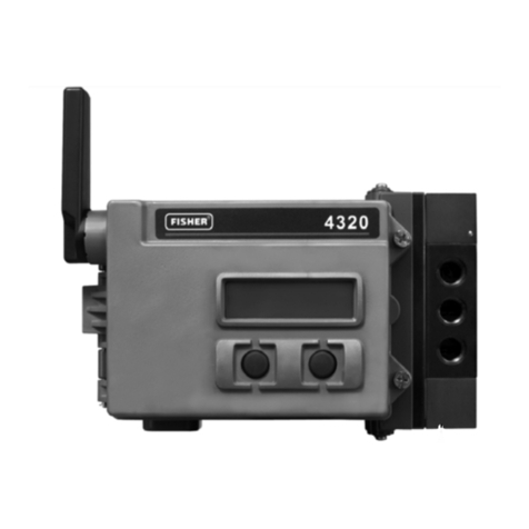
Emerson Fisher 4320 User manual

Emerson

Emerson Fisher 4320 User manual

Emerson RXi User manual

Emerson

Emerson RXi User manual

Emerson Liebert TM115 Assembly instructions

Emerson

Emerson Liebert TM115 Assembly instructions

Emerson ROSEMOUNT TankRadar REX RDU 40 User manual

Emerson

Emerson ROSEMOUNT TankRadar REX RDU 40 User manual

Emerson Fisher 4320 User manual

Emerson

Emerson Fisher 4320 User manual

Emerson Fisher 4320 User manual

Emerson

Emerson Fisher 4320 User manual

Emerson Fisher 4320 User manual

Emerson

Emerson Fisher 4320 User manual

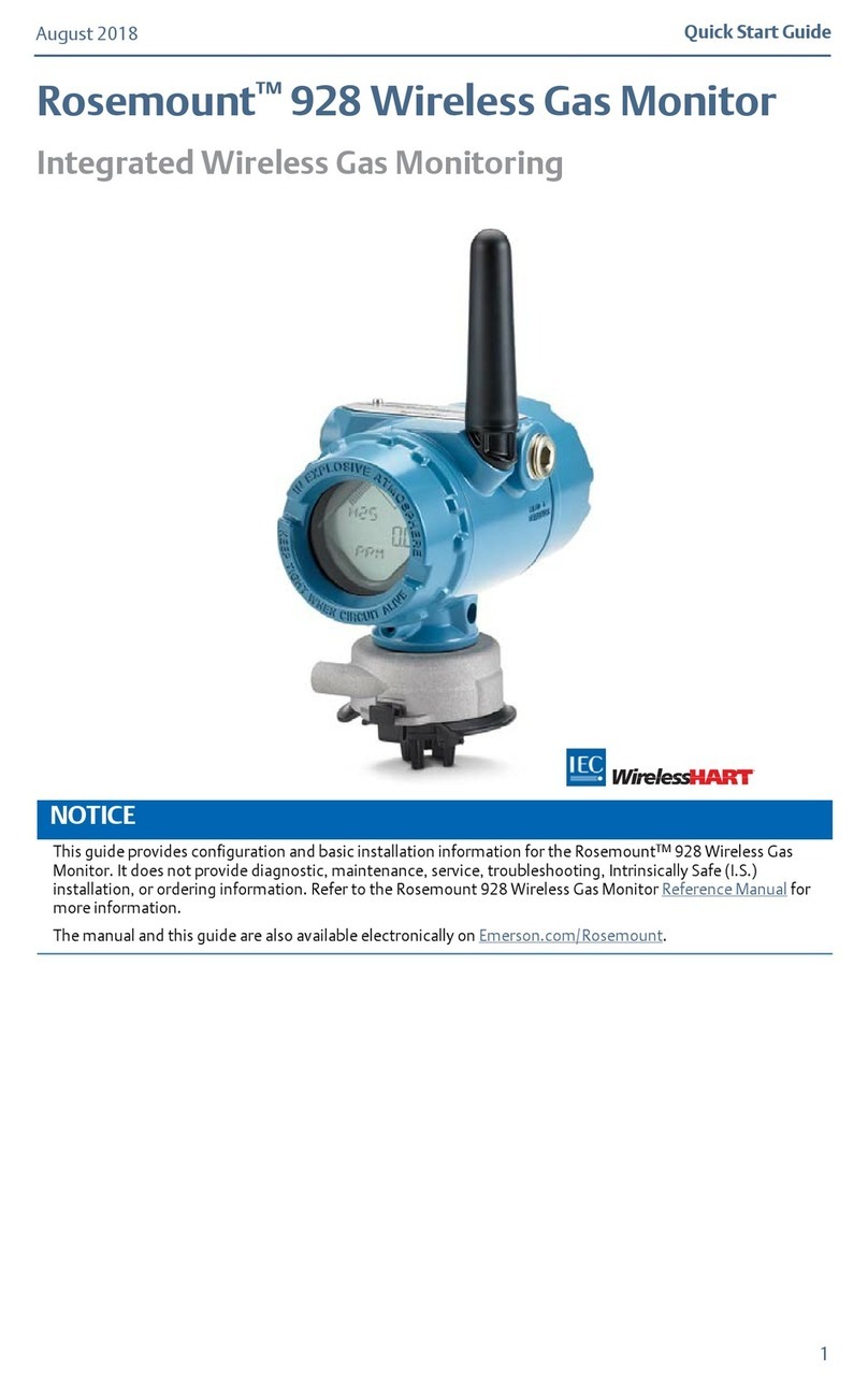
Emerson Rosemount 928 User manual

Emerson

Emerson Rosemount 928 User manual

Emerson MicroCEM User manual

Emerson

Emerson MicroCEM User manual

Emerson Machinery Health CSI 6500 User manual

Emerson

Emerson Machinery Health CSI 6500 User manual

Emerson TopWorx 4310 User manual

Emerson

Emerson TopWorx 4310 User manual

Emerson Rosemount 2230 User manual

Emerson

Emerson Rosemount 2230 User manual

Popular Monitor manuals by other brands

AOC E2451FH user manual

AOC

AOC E2451FH user manual

Memorex MT1701 user guide

Memorex

Memorex MT1701 user guide

Kenwood DMX1025BT quick start guide

Kenwood

Kenwood DMX1025BT quick start guide

Eizo FlexScan S1902SH user manual

Eizo

Eizo FlexScan S1902SH user manual

Itek ITMF24T061FHD user manual

Itek

Itek ITMF24T061FHD user manual

HP w19 - Widescreen LCD Monitor Service manual

HP

HP w19 - Widescreen LCD Monitor Service manual

ViewSonic GS773 user guide

ViewSonic

ViewSonic GS773 user guide

Metos DELI VRX1400-395 Installation and user manual

Metos

Metos DELI VRX1400-395 Installation and user manual

Philips 4CM2299 operating instructions

Philips

Philips 4CM2299 operating instructions

HP f2304 user guide

HP

HP f2304 user guide

Samsung SyncMaster 2494HM quick start guide

Samsung

Samsung SyncMaster 2494HM quick start guide

NEC AccuSync LCD72VXM user manual

NEC

NEC AccuSync LCD72VXM user manual

AUREL Magna Series manual

AUREL

AUREL Magna Series manual

Eizo FlexScan S2133 user manual

Eizo

Eizo FlexScan S2133 user manual

Samsung SyncMaster P50HP-2 quick start guide

Samsung

Samsung SyncMaster P50HP-2 quick start guide

LG L206WTG user guide

LG

LG L206WTG user guide

Tatung TME22W user manual

Tatung

Tatung TME22W user manual

MicroTouch OF-100P-A1 user manual

MicroTouch

MicroTouch OF-100P-A1 user manual

manuals.online logo
manuals.online logoBrands
  • About & Mission
  • Contact us
  • Privacy Policy
  • Terms and Conditions

Copyright 2025 Manuals.Online. All Rights Reserved.