Reference Manual
00809-0100-4828, Rev EA
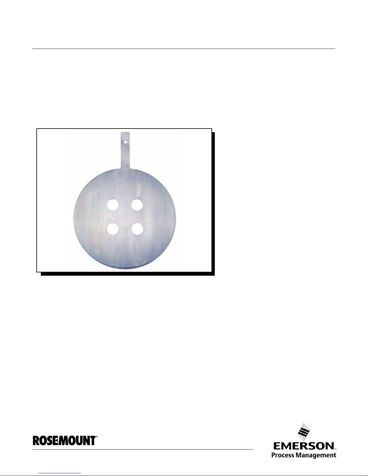
November 2007 Rosemount 1595
www.rosemount.com
Section 2 Installation
Safety Messages . . . . . . . . . . . . . . . . . . . . . . . . . . . . . . . . . page 2-1
Location and Orientation . . . . . . . . . . . . . . . . . . . . . . . . . . page 2-2
Installation . . . . . . . . . . . . . . . . . . . . . . . . . . . . . . . . . . . . . . page 2-5
SAFETY MESSAGES Instructions and procedures in this section may require special precautions to
ensure the safety of the personnel performing the operations. Please refer to
the following safety messages before performing any operation in this section.
Checklist The following is a summary of the steps required to complete a 1595
installation.
If this is a new installation, begin with step 1.
If the mounting is already in place, verify that the orifice flange size and rating
match the recommended specification and begin with step 5.
1. Determine where the 1595 is to be place within the piping system.
2. Establish the proper orientation as determined by the intended
service for the orifice plate.
3. Orient the 1595 Conditioning Orifice Plate so the pressure taps are
centered between any two (of four) orifice bore holes. In addition, the
pressure taps should be located at 90° to the plane of the last elbow.
4. Review “Location and Orientation” on page 2-2.
5. Confirm the 1595 configuration.
6. Measure the pipe’s internal diameter (I.D.), preferably at 1 x I.D. from
the orifice flange (upstream or downstream).
NOTE
Providing the pipe’s I.D. at the time of purchasing the 1595 is necessary to
maintain published orifice plate accuracy.
7. Install the orifice plate.
8. Check for leaks.
9. Commission the orifice plate.
Failure to follow these installation guidelines could result in death or serious injury:
• Make sure only qualified personnel perform the installation.
• Remove pressure and drain the pipe assembly prior to installing or removing the
orifice plate.
• If the process fluid is caustic or otherwise hazardous, follow the instruction closely
to prevent mishap.