9
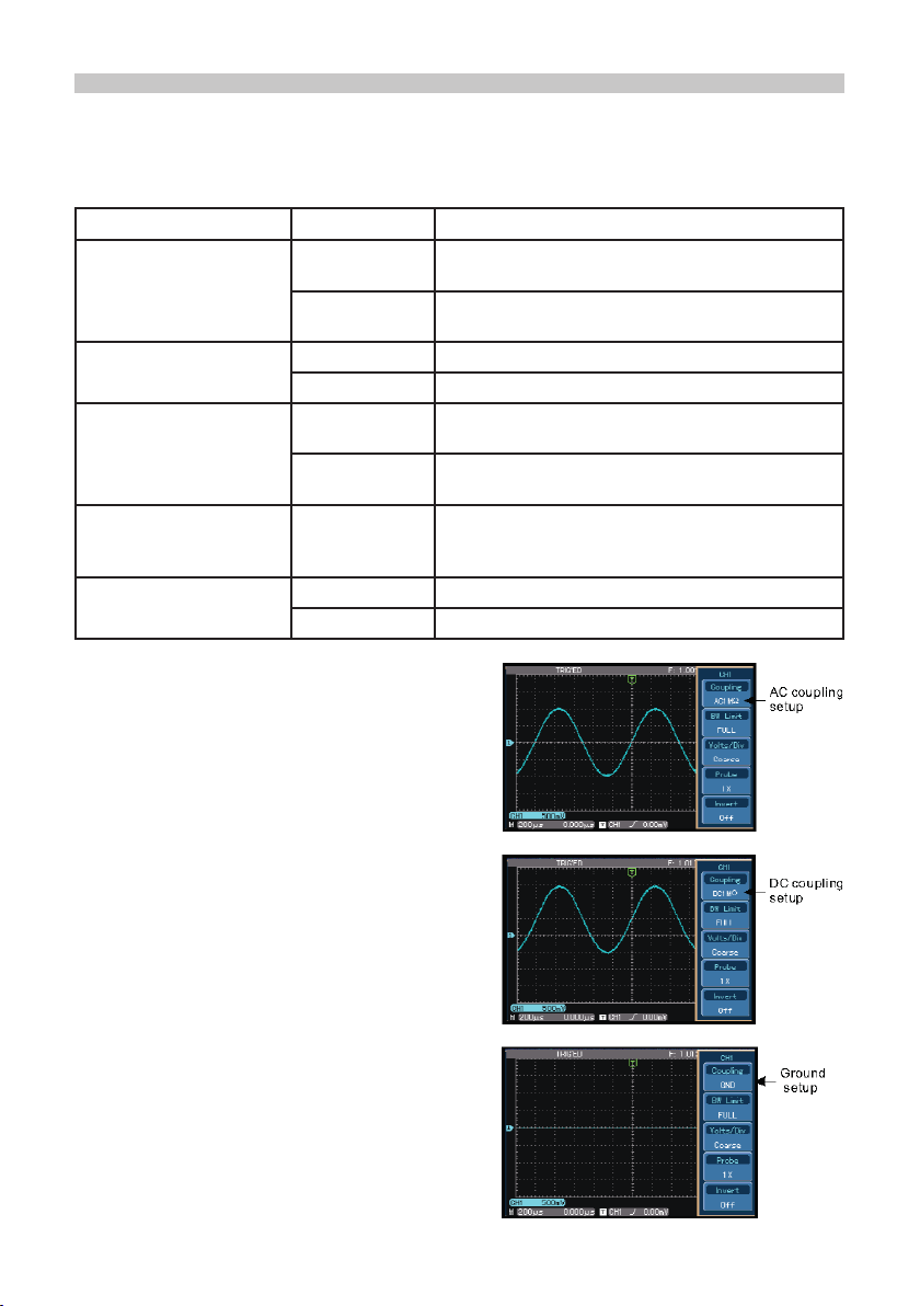
Select the FFT window
• Assuming the YT waveform is constantly repeating itself, the oscilloscope will carry
out FFT conversion of time record of a limited length. When this cycle is a whole
number, the YT waveform will have the same amplitude at the start and nish.
There is no waveform interruption.
• If the YT waveform cycle is not a whole number there will be different amplitudes
at the start and nish, resulting in transient interruption of high frequency at the
connection point. In frequency domain this is known as leakage.
• To avoid leakage multiply the original waveform by one window function to set the
value at 0 for start and nish compulsively. See the following table:
Notes
1. Upper Limit: effective only in low pass ltering - use MULTIPURPOSE control.
2. Lower Limit: effective only in high pass ltering - use MULTIPURPOSE control.
3. Y Offset: use MULTIPURPOSE control to move waveform vertically.
4. X Offset: use MULTIPURPOSE control to adjust vertical gratitude factor.
Digital Filtering Function
FFT Window Feature Most suitable measurement item
Rectangle
The best frequency resolution,
the worst amplitude resolution.
Basically similar to a status
without adding window.
Temporary or fast pulse. Signal level is
generally the same before and after.
Equal sine wave of very similar frequency.
There is broad-band random noise with
slow moving wave spectrum.
Hanning
Frequency resolution is better
than the rectangle window but
amplitude resolution is poorer.
Sine, cyclical and narrow-band random
noise.
Hamming
Frequency resolution is
marginally better than Hanning
window.
Temporary or fast pulse. Signal level varies
greatly before and after.
Blackman
The best amplitude resolution
and the poorest frequency
resolution.
Mainly for single frequency signals to
search for higher-order harmonic wave.
Note: FFT resolution means the quotient of the sampling and math points. When the
math point value is xed, the sampling rate should be as low as possible relative to the
FFT resolution.
• Nyquist frequency: To rebuild the original waveform, at least 2f sampling rate
should be used for waveform with a maximum frequency of f.
• This is known as Nyquist stability criterion, where f is the Nyquist frequency and 2f
is the Nyquist sampling rate.
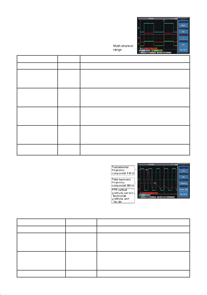
Functions
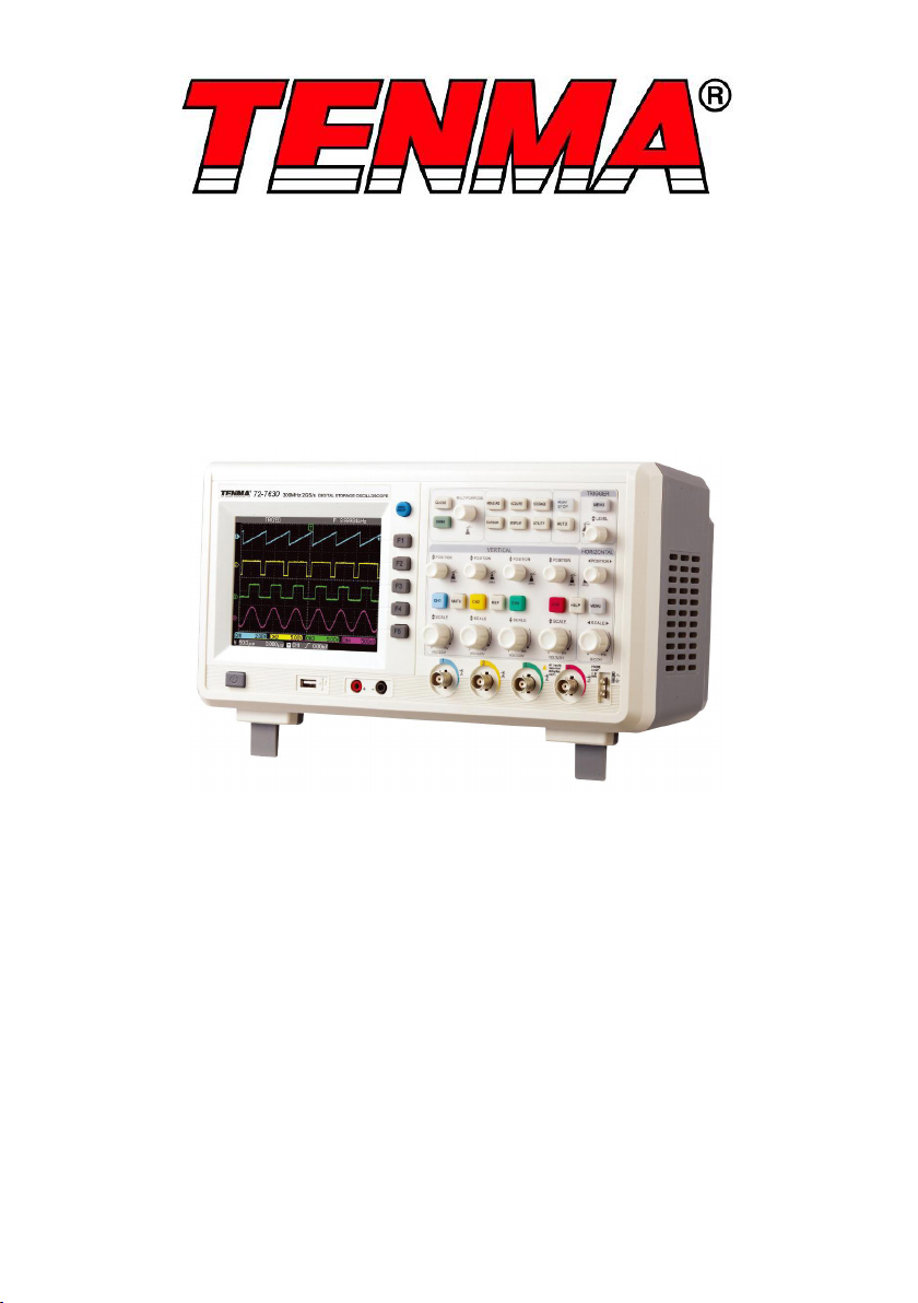
Menu Setup Notes
Type Filter Digital ltering
Source
CH1
CH2
CH3
CH4
Set CH1 as lter target
Set CH2 as lter target
Set CH3 as lter target
Set CH4 as lter target
Filter Type
Low Pass
High Pass
Band Pass
Set lter to low pass ltering
Set lter to high pass
ltering
Set lter to band pass
ltering