U9310090
M
MM
M
M
Your thermostat has the ability to reset all settings to the factory defaults. If you are certain you want
to do this: In standby mode(when thermostat is turned off), press and hold button and
for 5 seconds until RES is shown on LCD.
Configure the menu
Resetting factory defaults
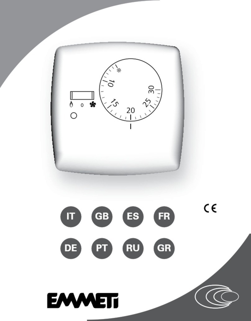
Setting temperature
Press or once, you will see set temperature flashing. Use or again to adjust
to the temperature you want your room to maintain. Press button to accept and exit.
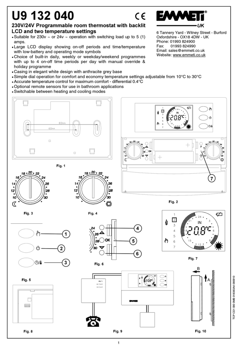
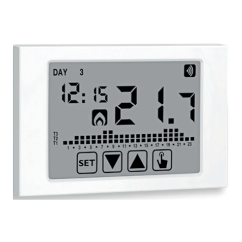
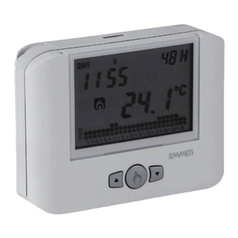
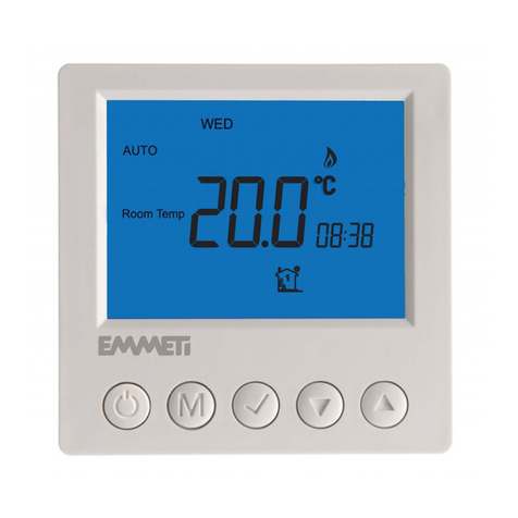
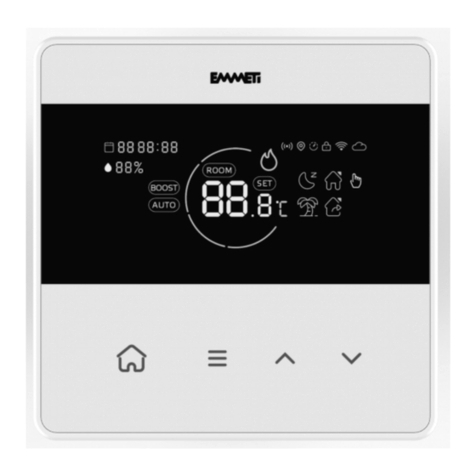
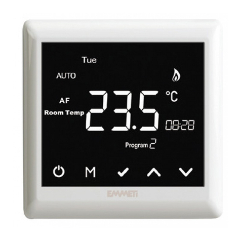
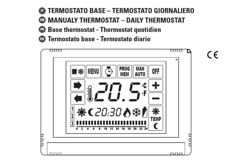
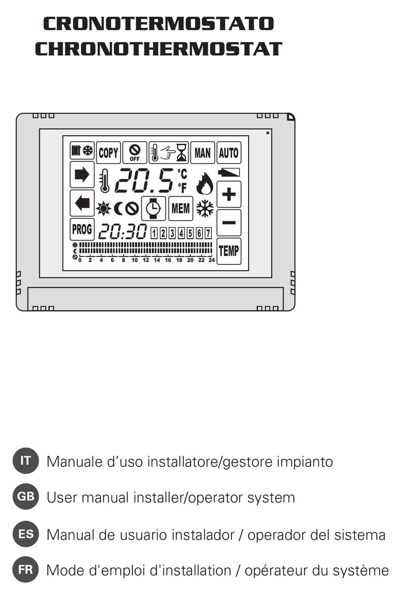
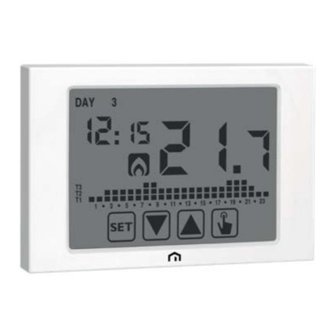
Buttons and LCD display
Buttons Press < 5 seconds Press > 5 seconds
Turning on/off thermostat
Menu button
Increase the set value
Decrease the set value
Lock /unlock buttons
Reset to factory settings
(when thermostat is turned off)
+
+
Confirm settings
The buttons are locked.
Displays when heating is active
Setback mode
Symbol Description
Set temperature
Set At
Sensor selection. This thermostat is a combination model allowing you to choose
between 3 different models. (A, AF,F )
Amodel: air only, with built in sensor
AF model: air & floo r , with both built in and remote sensor
F model: floor only, with remote sensor
Press and hold button for 5 seconds. Now you can see Menu 01, to proeceed to other menu, press button again. To exit menu, press button
First turn off the thermostat using the on/off button
Menu #
01
Switching differential.
Calibrate the room temperature. This feature is used to compensate for any difference
Calibrate the floor temperature. This feature is used to compensate for any difference
Set the floor temperature limit.
Select temperature format
06
07
08
09
10
03
04
05
02
Feature Description Factory Default
Feature Value
0
°C
40
°C
4°C
10°C
35°C
2°C~ 7°C
10°C~ 20°C
20°C~ 35°C
20
°C ~
40
°C
°C
/
°F
°C
A / AF / FA
Press or to select
The numbers of degree difference before switching.
between the displayed room temperature and a thermometer.
between the displayed floor temperature and a thermometer.
This feature is to protect the floor surface.
°C or °F.
The default is 1°C which means the thermostat will switch the
heating on
0.5°C below the set temperature and will turn it off 0.5°C above the set temperature.
With a 2°C differential,
the heating will switch on 1°C below the set temperature
and will switch off 1°C above the set temperature.
1°C 1°C ~ 5°C
-5°C ~ +5°C
0
°C -5°C ~ +5°C
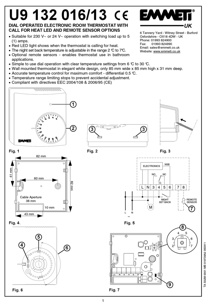
Installation and Wiring
Carefully separate the front half of the thermostat from the back plate by placing a
small flat head terminal driver into the slots on the bottom face of the thermostat.
Carefully unplug the ribbon connector which is plugged in to the front half of the thermostat.
Place the thermostat front half somewhere safe. Make the wiring connections as
Screw the thermostat back plate on to the back box.
shown in the diagram below.
Re-connect the thermostat ribbon cable and clip the
CS-11 LCD Digital Setback Thermostat
Frost protection. This is to avoid room temperature goes below 5°C.
The setback amount( the amount of temperature reduction)
on / offoff
Switched live
output 230V ~ 50Hz
LN
Link terminals 1
to 3 for 230VAC
live output
Remote sensor for floor
temperature control
Timeswitch live
for operaon
of temperature
setback mode
Registered Address: 6 Tannery Yard, Witney Street, Burford, Oxon., OX18 4DW
This gives you the option to limit the minimum set temperature
This gives you the option to limit the maximum set temperature
1. Please ensure that the electrical wiring of the installation and connections to and from the thermostat and any remote sensor connected to it are in accordance with BS 7671, the latest edition of the IET
Wiring Regulations.
2. The thermostat must be wired to the electric mains through a switch capable of disconnecting all poles compliant with the current safety standards and with a contact separation of at least 3 mm in all poles.
3. Before commencing work on the installation, the electricity supply must be disconnected.
4. The depth of the back box should be 35mm minimum.
WARNING
Please Note: one of the following error messages will appear if one of these problems occur:
E0, meaning the internal sensor is broken, short-circuit or not working properly.
E1, meaning the floor sensor is broken, short-circuit, not connected, or not working properly.
Single Zone
Multi Zone
1
ErP Class
+1%
8
ErP Class
+5%
two halves together.
