emmeti IM-U9132045 User manual

CRONOTERMOSTATO DIGITALE SETTIMANALE A BATTERIE
BATTERY-POWERED DIGITAL WEEKLY CHRONOSTAT

15
INSTALLATION ENGLISH
Fig. 1 Fig. 2
Method for releasing the
wall mount plate from the
base of the chronostat.

16
Fig. 3
LOAD
TELEPHONE
INTERFACE
The device is designed to be installed in a standard recess (or wall) mounted junction box with
two or three modules or else directly on the wall using the screw anchors provided.
To install the device carry out the following steps:
1. Release the wall mount plate fitted under the base of the chronostat as shown in Fig. 1.
2. Fix the plate directly on the wall or onto 2 or 3 module junction boxes by means of the two
holes for screws (distance between centres: 60 mm or 85mm), taking care to pass the wires
through the opening as shown in Fig. 2.
3. Make the electrical connections following the connection diagram in Fig. 3.
4. Fit the chronostat onto the wall mount plate, first matching up the teeth on the base with the
holes provided on the plate and then pressing downward on the device until the plastic teeth
of the plate click into place; then fix the chronostat body to the wall mount plate through the
two screws supplied which must be mounted in the battery holder (Fig. 2).
5. Insert the batteries in the battery compartment (O in Fig. 4); see paragraph ‘ HOW TO
INSERT/REPLACE THE BATTERIES ’.
WARNING
- To adjust properly room temperature, install the thermostat far from heat sources, airstreams or particularly cold walls (thermal
bridges).
- In order to grant the electrical safety, it is mandatory to screw the chronostat body to the wall mount plate through the two
screws supplied which must be mounted in the battery holder.
- If the load controlled by the relay of the chronostat operates with mains voltage, the connection must be made via an omnipolar
switch complying with current standards and with a contact opening of at least 3 mm in each pole.
- Installation and electrical wirings of this appliance must be made by qualified technicians and in compliance with the current
standards.
- Before wiring the appliance be sure to turn the mains power off.

17
DESCRIPTION OF CONTROLS
Fig. 4
A
C
B
G
H
I
LO
N
F
E
D
M
P P
LEGEND
A Cleaning Button: activates temporary suspension of
operation.
B Vacation Button: deactivates the device for a
programmable period of time.
C Programming Button: enters the programming menu
D Button with double function:
- In normal operation: activates the function 24 hours
Manual / Permanent Manual / Automatic
- In schedule programming: sets the regulation
temperature into Economy mode
E Button with double function:
- In normal operation: turns on and off the chronostat
- In schedule programming: sets the regulation
temperature into Off / Antifreeze mode
F Button with double function:
- In normal operation: displays current time or
temperature
- In schedule programming: sets the regulation
temperature into Comfort mode
G Forward button
H Economy mode knob
I OK button (confirmation)
L Back button
M Comfort mode knob
N Reset button
O Battery compartment
P Screws holes for fixing the chronostat body to the wall
mount plate

18
DISPLAY SYMBOLS
In the following is explained the meaning of some symbols which may
appear on the display:
Battery status indication.
Flashing:
Batteries discharged; replace batteries.
Temperature regulation in Comfort mode.
Temperature regulation in Economy mode.
Temperature regulation in Off / Antifreeze mode.
Chronostat off: antifreeze function active, the display
shows ‘OFF’.
Heating mode enabled.
Cooling mode enabled.
Temperature regulation in Comfort mode for 24 hours.
Permanent temperature regulation in Comfort mode.
The chronostat is in programming mode.
Flashing:
Cleaning program active (the remaining time is shown on
the display).
Flashing:
Vacation program active (the remaining time is shown on
the display).
Fixed:
Indicates that the telephone interface is active.
Flashing:
Indicates that the remote command received by the
telephone interface has been overridden by another local
request through the chronostat buttons.
24h
24h
P

19
GENERALITIES
This device is a battery-powered digital weekly chronostat for
controlling room temperature on three levels: Comfort, Economy
or Off/Antifreeze. The device can be used both in heating and air
conditioning systems.
The chronostat features a large backlit display which shows
all functional indications, the program schedule and the room
temperature reading or, alternatively, the current time.
Allows to set up to 7 different time schedules, each one different for
each day of the week, with a minimum intervention time of 1/2 hour
during 24 hours.
In addition, the device offers the possibility of setting the Antifreeze
temperature and the sensor Offset value.
STARTING UP
When starting up for the first time:
Insert the batteries in the battery compartment, observing the
polarities indicated (see paragraph ‘HOW TO INSERT/REPLACE
THE BATTERIES’) and carry out a reset operation by inserting a
pointed object through the hole provided (N in Fig. 4); DO NOT USE
NEEDLES OR TOOLS THAT COULD IRREPARABLY DAMAGE
THE CHRONOSTAT.
The buttons present beneath the lower flap are 3:
‘OK’: For programming the time and current day of the week (I in Fig. 4);
‘ ‘: Forward (G in Fig. 4);
‘ ’: Back (L in Fig. 4);
Setting the current time and day
To set the clock of the chronostat carry out the following steps:
1. Open the flap of the battery compartment.
2. Keep the ‘OK’ button pressed for at least 2 seconds; the hour
digits will start flashing.
3. Set the hour using buttons ‘ ‘ and ‘ ‘.
4. Confirm by pressing ‘OK’; the minute digits will start flashing.
5. Set the minutes using buttons ‘ ‘ and ‘ ‘.
6. Confirm by pressing ‘OK’; the box surrounding the current day of
the week will start flashing.
7. Set the current day of the week using buttons ‘ ‘ and ‘ ‘
(the current day is highlighted by a box surrounding the number
corresponding to the day of the week, 1 Monday .. 7 Sunday )
8. Confirm by pressing ‘OK’; the output of the time and day setting is
automatic.
Setting the Heating / Cooling mode
This setting is used to invert the operating logic of the relay according
to whether a heating or air conditioning unit is being controlled.
IMPORTANT: The chronostat leaves the factory set in the
heating mode.
To modify the operating logic, carry out the following procedure:
1. Keep the ‘ ‘ button pressed for at least 10 seconds.
A. If the chronostat was previously set on cooling, the heating
mode will be set and the ‘ ‘ (flame) symbol will flash on the
display for 8 seconds.

20
B. If the chronostat was previously set on heating, the cooling
mode will be set and the ‘ ‘ (fan) symbol will flash on the
display for 8 seconds.
During normal operation, if the heating mode is on, the ‘ ‘ icon will
remain lit, whereas if the cooling mode is on, the ‘ ‘ will remain
steadily lit.
Setting the Comfort and Economy temperatures
The Comfort temperature is set by means of the ‘ ‘ knob (M in
Fig. 4) whereas the Economy temperature is set by means of the ‘ ‘
knob (H in Fig. 4).
Note: In order to have a nighttime reduction, the economy
temperature must normally be set on a lower value than the
comfort temperature.
The chronostat will control the room temperature in the comfort or
economy mode according to the schedule programmed (see paragraph
‘SETTING THE USER PARAMETERS‘).
SETTING THE USER PARAMETERS
To enter the mode for setting the chronostat parameters, proceed
as follows:
1. Press the ‘ P ‘ button; the display will show the ‘ P ‘ icon (bottom
right) and the word ‘ PrOG ‘.
2. Press the ‘ P ‘ button repeatedly to scroll through the user
parameters:
Schedule Programming ‘ PrOG ’
Antifreeze Setting ‘ AFr ’
Optimization Function Setting ‘ OPt ’
Offset Setting ‘ OFS ’
3. Press the ‘OK’ button to modify the selected parameter.
4. Configure the data associated with each individual parameter as
illustrated below.
5. To exit the user parameter programming mode, press the ‘OK’
button to confirm the changes made or else wait 10 seconds
without pressing any button.
‘ PrOG ‘:SCHEDULE PROGRAMMING
Normally the dashes in the top and bottom parts of the display
show the operating mode (Comfort, Economy, Off/Antifreeze) of the
chronostat, whereas the section on the left shows the current day
of the week (1 Monday .. 7 Sunday), highlighted by a box around the
number to which the schedule refers.
To facilitate the programming operation it is sufficient to remember
this rule:

21
To set the program schedule proceed as described below:
Note: You will exit the programming mode without memorizing
the programmed schedule if more than 10 seconds elapse
and you do not press any button; or else you can confirm
the settings in sequence by pressing the ‘Ok’ button without
making any changes.
1. Select the parameter ‘PrOG’ and press ‘OK’: the display will show
the ‘ P ’ icon and the word ‘dAy’ and the boxes corresponding to
day or group of days will start flashing.
2. Press buttons ‘ ’ and ‘ ‘ to set the combination of days to be
programmed.
In the following the four available combinations are listed:
Note: For each day combination, the time schedule set will be
the same for all days within each single group.
3. Press the ‘ OK ‘ button to confirm the setting made; the display will
show the schedule previously programmed for the set day or group
of days and the time 00.00 (cursor flashing on the interval between
00.00 and 00.30).
4. Set the operating mode; to make the programming operation easier,
the chronostat leaves the factory preset with 4 time slots. Press
the ‘ ’ button to scroll cyclically through the four combinations of
time slots preset in the factory.
(Mo)
2nd combination
of days 7
2 3 4 5 61
1st combination
of days 76
2 3 4 51
2
3
4
5
6
7
1
4th combination
of days
(Schedule
Day by Day)
5 6 71 2 3 4
3rd combination
of days
(Fr)(Th)(We)(Tu) (Su)(Sa)
Economy mode:
one dash lit (bottom).
Days of the week:
1 Monday .. 7 Sunday.
The box indicates the
current day or group
of days.
Comfort mode:
two dashes lit.
Off/Antifreeze mode:
no dashes lit.

22
FOURTH TIME SLOT
Comfort mode Economy mode
6.00 .. 8.00 8.00 .. 11.00
11.00 .. 13.00 13.00 .. 17.00
17.00 .. 19.00 19.00 .. 21.00
21.00 .. 23.00 23.00 .. 6.00
FIRST TIME SLOT
Comfort mode Economy mode
6.00 .. 23.00 23.00 .. 6.00
SECOND TIME SLOT
Comfort mode Economy mode
6.00 .. 8.00 8.00 .. 17.00
17.00 .. 23.00 23.00 .. 6.00
THIRD TIME SLOT
Comfort mode Economy mode
6.00 .. 8.00 8.00 .. 11.00
11.00 .. 13.00 13.00 .. 17.00
17.00 .. 23.00 23.00 .. 6.00
Alternatively, if the time slots do not correspond to the desired schedule,
it is possible to change them manually by proceeding as follows:
5. Select the pre-set time slot which mostly fits the required time
schedule.
For every time interval (each dash corresponds to a half hour) set
the operating mode by pressing one of the following buttons:
Comfort mode: Press the ‘ ‘ button.
Off / Antifreeze: Press the ‘ ‘ button.
Economy mode: Press the ‘ ‘ button.
Moving the time cursor: Press button ‘ ’ or ‘ ‘.
Each time the button which sets the regulation mode is depressed,
the time cursor automatically jumps into the next half hour.
Confirm
Economy
Off
Comfort
6. After programming the schedule for the day or group of days
selected, press the ‘ OK ’ button.
The display will show the program schedule for the next day or
groups of days until the whole week is covered.
7. After programming the schedule for the entire week, press the
‘OK’ button. The chronostat will memorize the schedule set and
the word ‘MEMO’ will appear on the display; the device will
automatically exit the schedule programming mode.
The four time slots are preset as follows:

23
‘AFr’ ANTIFREEZE SETTING
The Antifreeze function allows you to select a minimum temperature to
be maintained when the chronostat is off, so as to protect both the room
and the equipment when the room temperature falls below the set value.
The device leaves the factory with the Antifreeze function set on 3°C.
IMPORTANT: the function is active only when the device has
been set in the heating mode.
To set the Antifreeze temperature, carry out the following steps:
1. Select the parameter ‘AFr’ and press the ‘OK’ button.
2. The display will show the previously set Antifreeze temperature.
3. Press buttons ‘ ’ and ‘ ‘ to change the setting (between OFF,
0.5°C..25°C); every change will be automatically memorized.
4. To exit press the ‘ OK ’ button or else wait 10 seconds without
pressing any button.
‘OPt’ OPTIMIZATION SETTING
The optimization function consists in the option of turning on the
heating or cooling earlier than the scheduled time in order to reach
the set temperature by the scheduled time.
The chronostat calculates the time necessary in order to reach the
desired temperature and turns on the heating in advance accordingly,
by the amount of time necessary to achieve the target.
The amount of time in advance may be 60 minutes at most and is
calculated based on the average gradient of the previous 24 hours.
To set the optimization function carry out the following steps:
1. Select the parameter ‘OPt’ and press the ‘OK’ button.
2. The display will show ‘On‘ or ‘Off‘.
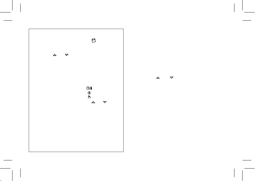
QUICK GUIDE FOR SETTING THE TIME SCHEDULE
Press button ‘ P ’.
The display shows ‘ PrOG ’ with the icon ‘ ‘ turned on.
Press button ‘ OK ’.
The display shows ‘ dAY ‘
Press buttons ‘ ‘ and ‘ ‘ in order to choose one of the four days
combinations available as pre-set.
Press button ‘ OK ’ to confirm the choice.
The display shows hour 00:00 with the relevant dash, in the
upside right, flashing.
Press one of the following buttons to select the temperature
regulation level desired:
Comfort mode: Press the ‘ ‘ button.
Off / Antifreeze: Press the ‘ ‘ button.
Economy mode: Press the ‘ ‘ button.
Moving the time cursor: Press button ‘ ’ or ‘ ‘.
Each time the button which sets the regulation mode is depressed,
the time cursor automatically jumps into the next half hour.
Once the time schedule for the day or group of days selected has
been set, press button ‘ OK ’.
The display will show the time schedule for the next day or group
of days until the whole week has been covered.
Once the time schedule for the whole week has been set, press
button ‘ OK ’. The chronostat will store the program into its
memory and the word ‘ MEMO ’ is shown on the display, then it
will automatically quit the time schedule setting procedure.
•
•
•
•
•
•
•
•
•
•
P

24
VACATION PROGRAM
If you intend to be away for a relatively long period it is advisable
to activate the Vacation Program, which will suspend the active
operating mode for the desired number of hours (from 1 to 95) or
days (from 1 to 99).
At the end of the set number of hours or days, the chronostat will
go back into the operating mode it was in prior to activation of the
Vacation Program. While it is off, the Antifreeze function will still be
active and the ‘ ‘ symbol will be shown on the display, along with
the countdown of the time remaining until the end of the program.
Note: Access to the vacation program will NOT be enabled while the
‘ cleaning program ‘ is on.
To activate the vacation program proceed as follows:
1. Press the ‘ ‘ button: the display will show the ‘ ‘ symbol and
the time ‘ h 00 ‘.
2. Press buttons ‘ ’ and ‘ ‘ to set the vacation time; every
change will be automatically memorized.
Up to 95 hours, the programming is indicated in hours and the
display will show ‘ h XX ‘.
Once that value is exceeded, the device will automatically switch
to the mode for programming the vacation time in days and display
will show ‘ d XX ‘. It will be possible to increase or decrease the
hour or day by one unit at a time, with values ranging from 0 .. 95
hours and 4 .. 99 days.
3. To activate the vacation program for the set time, press the ‘ OK ’
button again or else wait 10 seconds without pressing any button;
The display will show the flashing ‘ ’ icon and the time remaining
3. Press button ‘ ’ to activate (On) or ‘ ‘ to deactivate (Off) the
function; every change will be automatically memorized.
4. To exit press the ‘ OK ’ button or else wait 10 seconds without
pressing any button.
‘OFS’ OFFSET SETTING
With the Offset function it is possible to correct the temperature
reading of the device by ±5°C in order to correct any systematic
reading errors due to a positioning of the chronostat in areas
unsuitable for measuring the room temperature. The device leaves
the factory with the Offset set at 0.0°C.
To adjust the Offset temperature, carry out the following steps:
1. Select the ‘ OFS ’ parameter and press the ‘ OK ’ button.
2. The display will show the previously set Offset temperature.
3. Press buttons ‘ ’ and ‘ ‘ to modify the setting (range:
-5.0°C .. +5.0°C); every change will be automatically memorized.
4. To exit press ‘ OK ’ button or else wait 10 seconds without
pressing any button.
CLEANING PROGRAM
This program is particularly useful during cleaning when windows are
open and it is pointless either to heat or air condition rooms. In such
cases the relay will remain Off for a maximum period of two hours.
To activate the program press the ‘ ‘ button: on the display the ‘ ‘
icon will light up and in place of the clock, the time remaining until the
resumption of normal operation will be displayed.
The device will go back to the previous operating mode after two
hours or if you press the ‘ ‘ button again.

25
until the end of the vacation period.
4. To deactivate the vacation function and resume normal operation,
press the button ‘ ’ button or ‘ ‘.
SWITCHING OFF - ANTIFREEZE FUNCTION
To deactivate the chronostat press the ‘ ‘ button.
The display will show the word ‘ OFF ’.
If the chronostat has been set in the heating mode, the Antifreeze
function will be active and the ‘ ‘ symbol will appear on the display;
in such a case the room temperature will be controlled based on the
value set for the Antifreeze temperature (see paragraph ‘SETTING
THE USER PARAMETERS‘).
AUTOMATIC OPERATION / 24h MANUAL / PERMANENT
MANUAL OVERRIDE FUNCTION
By pressing the ‘ ‘ button, you can override the program schedule
and the chronostat will control the room temperature according to the
temperature set with the ‘ ‘ knob.
By pressing the ‘ ‘, button repeatedly you can switch from Automatic
to 24 hour Manual, from 24 hour Manual to Permanent Manual and
from Permanent Manual back to Automatic.
During manual operation the display doesn’t show the time schedule,
but only the room temperature, the state of relay (with possible
symbols ‘ ‘ or ‘ ‘), the symbol ‘ ‘ (24h manual) or ‘ ‘ (permanent
manual) and the symbol ‘ ‘.
Pressing the ‘ ‘ button once will activate the 24 hour Manual mode
and the chronostat will remain in this mode until the time 23:59 is
reached, after which it will go back into the Automatic mode.
Note: If the device is set in the 24h Manual mode and the Vacation
program is activated, after the Vacation period has elapsed, if it is
past the time 23.59, the chronostat will go back into the Automatic
mode and follow the set program schedule.
Pressing the ‘ ‘ button a second time will switch the chronostat into
the Permanent Manual mode and it will remain in this mode until you
press the ‘ ‘ button again.
BACKLIGHTING
The display backlight turns on whenever and button is pressed. It turns
off automatically 20 seconds after the last pressing of a button.
TIME / TEMPERATURE INDICATION
By pressing the ‘ ‘ button you can alternatively display the current
time or room temperature reading (corrected by the set Offset value).
IMPORTANT: In order to optimize battery life, the chronostat
reads the room temperature every 3 minutes and activates or
deactivates the relay accordingly.
HOW TO INSERT / REPLACE BATTERIES
The battery charge status is constantly displayed by means of the
‘ ‘ symbol.
The battery charge is at a maximum if all three level indicators are
lit inside the symbol.
If the ‘ ‘ symbol (completely empty) flashes, it means that the
batteries are depleted and must be replaced.
To replace the batteries proceed as follows:
1. Open the flap of the battery compartment (Fig. 4).
24h

26
2. Remove the batteries, prying them out with the aid of a tool if
necessary.
3. Insert the new batteries, which must be alkaline 1.5V type AA.
4. If necessary, reset the device by means of button N shown in
Fig. 4; DO NOT USE NEEDLES OR TOOLS THAT COULD
IRREPARABLY DAMAGE THE Chronostat.
5. Check that the time is set correctly; adjust the setting if necessary.
CONNECTION TO A TELEPHONE INTERFACE
The chronostat offers the option of connecting a telephone interface with
continuous operation (latching relay) to terminals 8 and 9.
Use of a suitable telephone interface does not require any setting
to be made on the chronostat; for directions on using the telephone
interface see the instruction manual provided.
Via a telephone interface it is possible to turn the chronostat Off or
turn it On in the Permanent Manual mode.
Depending on the commands received from the telephone interface the
chronostat will act according to the following operating logic:
1. Telephone interface contact closed:
The chronostat will switch into the ‘Permanent Manual’ mode: the
‘ ‘ and ‘ ‘ symbols will be shown on the display.
2. Telephone interface contact open, after (and only after) a previous
closure, if no buttons have been pressed (Manual/Off):
The chronostat will be switched off and the word ‘OFF‘ will be
displayed along with the ‘ ‘ symbol. If the ‘Antifreeze’ function
is active the ‘ ‘ symbol will be displayed.
IMPORTANT: the commands input by pressing the control
buttons will always have priority over the commands received
from the telephone interface.
If you press the ‘ ’ or ‘ ’ button on the chronostat, the device
will change its status and the ‘ ’ icon will flash to indicate that
the interface command has been overridden by a command input with
a control button.
The ‘ ’ icon will stop flashing if the telephone interface sends the
chronostat the same command as the one made with the button or
if the telephone interface is reset. In such a case the status set by
means of the control button will not be changed and the chronostat
will be ready to receive a new command.
IMPORTANT
If an Off command is sent to the chronostat via the telephone
interface (contact open), it is a good idea to check that the
command has been executed by the chronostat by carrying out
the following realignment procedure:
1. Using the functions of the telephone interface, check that the
contact is open, sending an Off command if necessary.
2. Send a command to the telephone interface to close the
contact (the chronostat will turn on).
3. Using the functions of the telephone interface, check that the
contact is closed.
4. Send a command to the telephone interface to open the
contact (the chronostat will turn off).
During this sequence no commands should be input with the control
buttons as they have priority over the interface commands.

27
TECHNICAL CHARACTERISTICS
Power supply: 2 x 1.5V, alkaline batteries (Type AA)
Battery life: >1 year
Backlight turns off: 20 sec. after the last pressing of a button
Setting range: comfort: 5°C .. 35°C
economy: 5°C .. 35°C
Differential: 0.2°C (asymmetrical)
Antifreeze: OFF/0.5°C .. 25.0°C (Default 3.0°C)
Offset: ± 5.0°C. (Default 0.0°C)
Sensor type: NTC 4K7 ohm ±1% @ 25°C (Internal)
Precision: ±1.0°C
Resolution: 0.1°C. ( 0.0°C .. 50.0°C)
0.2°C. (-9.9°C .. -0.1°C)
Contact rating: 5(1)A @ 250V~ SPDT
Protection rating: IP 30
Insulation class: II ( )
Number of manual cycles: 1,000
Number of automatic cycles: 100,000
Type of action: 1CU
Tracking index: PTI 175
Pollution situation: 2 (normal)
Overvoltage category: II
Operating temperature: 0°C .. +40°C
Storage temperature: -10°C .. +50°C
Humidity limits: 20% .. 80% RH non-condensing
Enclosure: Material: ABS+PC V0 self-extinguishing
Colour: Cover: Signal white (RAL 9003)
Base: Anthracite (RAL 7016)
Weight: ~ 250 gr.
NORMATIVE REFERENCES
The product complies with the following standards (EMC 2004/108/EC
and LVD 2006/95/EC):
CEI-EN-60730-1 (2002)
CEI-EN-60730-2-7 (1998)
CEI-EN-60730-2-9 (1998)
WARRANTY
In the view of a constant development of their products, the
manufacturer reserves the right for changing technical data and
features without prior notice. The consumer is guaranteed against any
lack of conformity according to the European Directive 1999/44/EC as
well as to the manufacturer’s document about the warranty policy. The
full text of warranty is available on request from the seller.
DIMENSIONS (in mm)

@IST01550AAN 019307A0 230511
Table of contents
Other emmeti Thermostat manuals

emmeti
emmeti CS-11 User manual

emmeti
emmeti CHRONOTHERMOSTAT User manual

emmeti
emmeti U9132040 User manual

emmeti
emmeti TAE-15 User manual

emmeti
emmeti 01514228 User manual

emmeti
emmeti CS-11 User manual

emmeti
emmeti CS-17 User manual

emmeti
emmeti CTUP User manual

emmeti
emmeti 01350340 User manual

emmeti
emmeti CTTS RF User manual
Popular Thermostat manuals by other brands

Honeywell
Honeywell T4360G installation instructions

Danfoss
Danfoss living connect Z installation guide

Theben
Theben RAMSES 366/1 top2 Installation and operating instructions

AURATON
AURATON R30 RT owner's manual

Honeywell
Honeywell UtilityPRO Series operating manual

Beijer Electronics
Beijer Electronics X2 base 10 v2 installation manual