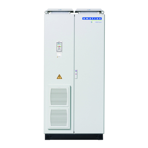
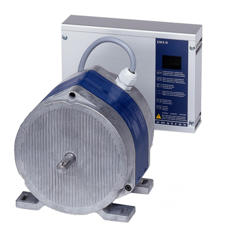
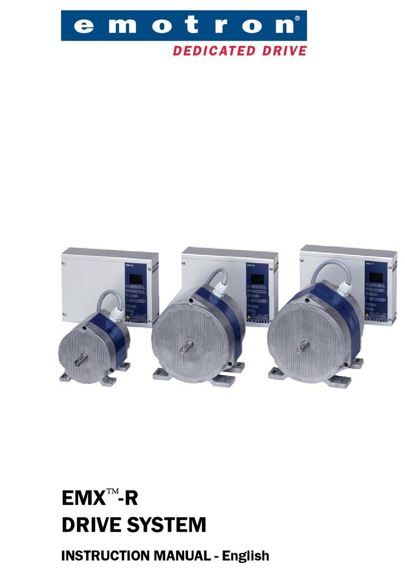
Emotron EMX-D User manual


Emotron EMX-D
Drive system for
rotary heat exchanger
Instruction manual
English


CG Drives & Automation, 01-5139-11r1 1
Addendum
Addendum valid for Emotron EMX-D
This addendum belongs to the instruction manual with document number:
01-5016-01r0 for Emotron EMX-D
Installation of the driveunit (motor plus reduction gear)
• Mount the drive unit.
Attached to the Gearbox you will find a ventilation plug and
a brief “Installation and Maintenance instruction”. Follow
these instructions together with the following:
• On the gearbox there are three plugs.
Before starting up, remove the plug in highest
position, check the oil level and add oil if necessary.
Use lubricant according to the type plate. Quantity of
lubricant in the gearbox is 0,25 litre.
Fig. 1 Recommended oil level in the gearbox depending on shaft position.
• Now replace the plug you removed with the ventilation
plug (the plug attached to the gearbox) and fasten it.
Fig. 2 Remove the plug in highest position and replace with
the ventilation plug.
Lubricant level (0,25 L)
NOTE: It is important to replace the plug in highest
position with the ventilation plug (included in delivery).
This to prevent oil leakage at thermal changes.

2CG Drives & Automation, 01-5139-11r1
Addendum
Select language
As default, the language in the control panel display and
menu system is set to English. One of the first things to do
during commissioning is to select desired language in the
system.
There are two ways to select language.
1. Follow the Instruction manual and select language
according to chapter 7.3.1 Operation menu [210]
2. It is also possible to press the Toggle Key and you will
come directly to menu “Language[211]”.
Fig. 3 Control panel
The Toggle and Loc/Rem Key
This key is a quick access to menu
“Language [211]”. Press this key if you would
like to change the language in menu system
and Control panel display.
Language [211]
Select the language used in menu system and
on the LCD display.
• Press or key until desired Language is
displayed.
• Save/Confirm the selected language by pressing
key.
LC Display
LEDs
Control Keys*
Toggle Key
Function Keys
PREV NEXT ESC
ENTER
RESET
LOC/
REM
* Not used
Default: English
English 0 English selected
Svenska 1 Swedish selected
Nederlands 2 Dutch selected
Deutsch 3 German selected
Français 4 French selected
Español 5 Spanish selected
Руccкий 6 Russian selected
Italiano 7 Italian selected
Česky 8 Czech selected
211 Lan g u age
St p Engl i s h
A

Emotron EMX-D
INSTRUCTION MANUAL - ENGLISH
Software version 4.2x
Document number: 01-5016-01
Edition: r0
Date of release: 2010-09-01
© Copyright Emotron AB 2010
Emotron retains the right to change specifications and illustrations in the
text, without prior notification. The contents of this document may not
be copied without the explicit permission of Emotron AB.


Emotron AB 01-5016-01r0
Safety Instructions
Instruction manual
Read this instruction manual before installing and running
the drive system.
Handling the drive system
Installation, commissioning, demounting, taking
measurements, etc, of or on the drive system may only be
carried out by personnel technically qualified for the task.
The installation must be carried out in accordance with local
standards.
Opening the control unit
Always take adequate precautions before opening the control
unit. Although the connections for the control signals and
the switches are isolated from the mains voltage, do not
touch the control board when the drive system drive system
is switched on.
Precautions tobe taken with a
connected motor
If work must be carried out on a connected motor or on the
driven machine, the mains voltage must always be discon-
nected from the drive system first. Wait at least 5 minutes
before starting work.
Earthing
The controlunit must always be earthed via the mains safety
earth connection.
EMC Regulations
In order to comply with the EMC Directive, it is absolutely
necessary to follow the installation instructions. All installa-
tion descriptions in this manual follow the EMC Directive.
Voltage tests (Megger)
Do not carry out voltage tests (Megger) on the motor, before
all the motor cables have been disconnected from the drive
system.
Condensation
If the control unit is moved from a cold (storage) room to a
room where it will be installed, condensation can occur.
This can result in sensitive components becoming damp. Do
not connect the mains voltage until all visible dampness has
evaporated.
Incorrect connection
The control unit is not protected against incorrect connec-
tion of the mains voltage, and in particular against connec-
tion of the mains voltage to the motor outlets U, V and W.
The control unit can be damaged in this way.
Transport
To avoid damage, keep the drive system in its original pack-
aging during transport. This packaging is specially designed
to absorb shocks during transport.
DC-link residual voltage
WARNING: Always switch off the mains voltage
before opening the control unit and wait at
least 5 minutes to allow the buffer capacitors
to discharge.
WARNING: After switching off the mains
supply, dangerous voltage can still be
present in the control unit. When opening the
control unit for installing and/or
commissioning activities wait at least 5 minutes. In
case of malfunction a qualified technician should check
the DC-link or wait for one hour before dismantling the
control unit for repair.

Emotron AB 01-5016-01r0

Emotron AB 01-5016-01r0 3
Contents
Safety Instructions ......................................... 1
Contents.......................................................... 3
1. Introduction..................................................... 5
1.1 Delivery and unpacking ............................................ 5
1.2 Using of the instruction manual............................... 5
1.3 Standards .................................................................. 5
1.3.1 Recommendations with respect to EMC ................. 5
1.4 Dismantling and scrapping....................................... 6
1.4.1 Disposal of old electrical and electronic
equipment ................................................................. 6
2. General description ........................................ 7
2.1 Emotron EMX -D is available with different
gearboxes .................................................................. 7
2.2 Accessories................................................................ 7
2.3 Built-in functions ....................................................... 8
2.3.1 Automatic purging ..................................................... 8
2.3.2 Rotation monitor ....................................................... 8
2.3.3 Display of exact rotation speed................................ 8
2.3.4 Alarm relay................................................................. 8
2.3.5 Priority switch ............................................................ 8
2.3.6 Analogue output ........................................................ 8
2.3.7 Absolute humidity...................................................... 8
2.3.8 Protection of control unit and motor........................ 8
3. Installation ...................................................... 9
3.1 Basic installation....................................................... 9
3.2 Mounting the rotation monitor ................................. 9
3.3 Choice of pulley diameter......................................... 9
3.4 Cable connections................................................... 10
3.4.1 Mains cables ........................................................... 10
3.4.2 Motor cables............................................................ 10
3.4.3 EMC recommendations .......................................... 11
4. Control Connections.................................... 13
4.1 Control board........................................................... 13
4.2 Terminal connections ............................................. 14
4.3 Inputs configuration
with the switches..................................................... 14
4.4 Connection example ............................................... 15
4.4.1 Cables ...................................................................... 16
4.4.2 Types of control signals .......................................... 16
4.4.3 Screening................................................................. 16
4.4.4 Current signals ((0)4-20 mA).................................. 17
4.4.5 Twisted cables......................................................... 17
4.4.6 Manual control using 10 kpotentiometer ......... 17
4.4.7 Switching off ............................................................ 17
5. Getting Started ............................................ 19
5.1 Connect the mains and motor cables.................... 19
5.2 Remote control........................................................ 19
5.2.1 Connect control cables and set direction
of rotation ................................................................ 19
5.2.2 Switch on the mains ............................................... 19
5.2.3 Run the drive system .............................................. 19
5.3 Using the function keys .......................................... 20
6. Operation via the Control Panel.................. 21
6.1 General .................................................................... 21
6.2 The control panel .................................................... 21
6.2.1 The display............................................................... 21
6.2.2 LED indicators ......................................................... 22
6.2.3 Function keys .......................................................... 22
6.3 The menu structure ................................................ 22
6.3.1 The main menu ....................................................... 23
6.4 Programming during operation .............................. 23
6.5 Editing values in a menu ........................................ 23
6.6 Programming example............................................ 24
7. Functional Description ................................ 27
7.1 Normal View [100] .................................................. 27
7.2 EMX-D Options[O00] ............................................... 27
7.2.1 EMX-D Pars[010]..................................................... 27
7.3 Main Setup [200].................................................... 29
7.3.1 Operation [210]....................................................... 29
7.4 View reference [300] .............................................. 29
7.4.1 View Reference speed [310].................................. 29
7.5 View Operation/Status [700] ................................. 29
7.5.1 Operation [710]....................................................... 29
7.5.2 Status [720] ............................................................ 30
7.5.3 Stored values [730] ................................................ 32
7.6 View Trip Log [800] ................................................. 32
7.6.1 Trip Message log [810]........................................... 32
7.6.2 Reset Trip Log [8A0] ............................................... 33
8. Troubleshooting, Diagnoses and Mainte-
nance 35
8.1 Trips, warnings and limits....................................... 35
8.2 Trip conditions, causes and remedial action ........ 35
8.2.1 Technically qualified personnel.............................. 36
8.2.2 Opening the variable speed drive .......................... 36
8.2.3 Precautions to take with a connected motor ........ 36
8.2.4 Auto reset Trip ......................................................... 36
8.3 Maintenance ........................................................... 38
9. Technical Data ............................................. 39
9.1 Dimensions.............................................................. 40
9.2 Control signals......................................................... 41
10. Menu List ...................................................... 43
Index ............................................................. 45
4Emotron AB 01-5016-01r0

Emotron AB 01-5016-01r0 Introduction 5
1. Introduction
Emotron EMX-D is a speed-controlled drive system spe-
cially designed for driving rotary heat-exchangers. The sys-
tem comprises an enclosed control unit and a motor unit
with worm reduction gear, which are linked by two cables.
The control unit is driven by a single-phase power supply,
230 VAC, 50/60 Hz.
The following symbols can appear in this manual. Always
read these first before continuing:
Users
This instruction manual is intended for:
• installation engineers
• maintenance engineers
•operators
• service engineers
1.1 Delivery and unpacking
Check for any visible signs of damage. Inform your supplier
immediately of any damage found. Do not install the drive
system if damage is found.
1.2 Using of the instruction
manual
Check that the software version number on the first page of
this manual matches the software version in the control unit.
With help of the index and the contents it is easy to track
individual functions and to find out how to use and set
them.
1.3 Standards
The variable speed drives described in this instruction man-
ual comply with the standards listed in Table 1. For the dec-
larations of conformity and manufacturer’s certificate,
contact your supplier for more information or visit
www.emotron.com.
1.3.1 Recommendations with respect to
EMC
In order to fulfil the European EMC Directive 2004/108/
EC regarding electromagnetic compatibility, the following
precautions must be taken:
• The motor cable must be mounted as close to the heat
exchanger housing as possible. If the cable is too long,
the excess should be collected together in the form of, for
example, a figure “8”. The area enclosed by the cable
should be as small as possible. Electrical tape or cable ties
can be used to achieve this.
Fig. 1 Excess motor cable should be arranged such that the
area enclosed is as small as possible
Special EMC couplings/glands are necessary. An EMC filter
is built into all EMX-D units,
NOTE: Read this instruction manual carefully before
starting installation, connection or working with the
drive system.
NOTE: Additional information as an aid to avoid
problems.
CAUTION: Failure tofollow these instructions
can result in malfunction or damage tothe
drive system.
WARNING: Failure tofollow these instructions
can result in serious injury tothe user in addition
to serious damage tothe drive system.
!
CAUTION: In order to comply fully with the
standards stated in the Manufacturer’s
Declaration ANNEX IIB, the installation
instructions detailed in this instruction
manual must be followed to the letter.
Wrong
Correct
!

6Introduction Emotron AB 01-5016-01r0
1.4 Dismantling and scrapping
The enclosures of the drives are made from recyclable mate-
rial as aluminium, iron and plastic. Each drive contains a
number of components demanding special treatment, for
example electrolytic capacitors. The circuit boards contain
small amounts of tin and lead. Any local or national regula-
tions in force for the disposal and recycling of these materials
must be complied with.
1.4.1Disposal of old electrical and
electronic equipment
This symbol on the product or on its packag-
ing indicates that this product shall be taken to
the applicable collection point for the recycling
of electrical and electronic equipment. By
ensuring this product is disposed of correctly,
you will help prevent potentially negative con-
sequences for the environment and human health, which
could otherwise be caused by inappropriate waste handling
of this product. The recycling of materials will help to con-
serve natural resources. For more detailed information about
recycling this product, please contact the local distributor of
the product or visit our home page www.emotron.com.
Ta b l e 1 St a n d a r d s
Market Standard Description
European
Machine Directive 98/37/EEC
EMC Directive 2004/108/EEC
Low Voltage Directive 2006/95/EC
WEEE Directive 2002/96/EC
All
EN 60204-1
Safety of machinery - Electrical equipment of machines
Part 1: General requirements.
Machine Directive: Manufacturer’s certificate
acc. to Appendix IIB
EN(IEC)61800-3:2004
Adjustable speed electrical power drive systems
Part 3: EMC requirements and specific test methods.
EMC Directive: Declaration of Conformity and
CE marking
EN(IEC)61800-5-1 Ed.
2.0
Adjustable speed electrical power drive systems Part 5-1.
Safety requirements - Electrical, thermal and energy.
Low Voltage Directive: Declaration of Conformity and
CE marking
IEC 60721-3-3
Classification of environmental conditions. Air quality chemical vapours, unit in
operation. Chemical gases 3C1, Solid particles 3S2.
Optional with coated boards
Unit in operation. Chemical gases Class 3C2, Solid particles 3S2.
UL508C UL Safety standard for Power Conversion Equipment

Emotron AB 01-5016-01r0 General description 7
2. General description
Emotron EMX-D is a speed-controlled drive system spe-
cially designed for driving rotary heat-exchangers. The sys-
tem comprises an enclosed control unit and a motor unit
with worm reduction gear, which are linked by two cables.
The control unit is driven by a single-phase power supply,
230 VAC, 50/60 Hz.
Emotron EMX-D has numerous built-in features making it
ideal for this particular application:
• No initial trimming is required.
• Soft starting/soft stop.
• Electronic motor protection.
• The drive system is designed to suit most types of
control signal.
• The control inputs are galvanically-isolated.
• The operational status of the system can be displayed.
• High efficiency.
Furthermore, the drive system has a built-in linearity
function that gives a linear relationship between the control
signal and the efficiency of the heat exchanger rather than
having the speed of rotation proportional to the control sig-
nal. This provides good conditions for stable
temperature control.
Fig. 2 Relation between control signal and motor speed -
Normal conditions
Fig. 3 Relation between control signal and motor speed when
using special MCC parameters, see further in
chapter 7.2.1 page 27.
2.1 Emotron EMX -D is
available with different
gearboxes
2.2 Accessories
The following items can be ordered separately:
- 100%
Control signal
200 rpm
8 rpm
Purging
Motor speed
2 rev. /10 min
1.5 V 10V
Order
number Name Reduction Gear
rpm
01-5071-00 EMX-D Motor
10.3:1 10.3:1 8 - 200 rpm
01-5071-10 EMX-D Motor 10.3:1
with 60mm outgoing shaft
01-5072-00 EMX-D Motor
15.5:1 15.5:1 5 - 135 rpm
01-5070-00 EMX-D Control unit
Order No Description
01-5073-00 Cable glands kit
01-4995-00 3.1 m PTC cable 2 x 0.75 mm2, screened
01-4995-10 2.9 m motor cable, 4 x 1.5 mm2, screened
01-5074-00 Rotation sensor with magnet and screened
cable.
135 rpm
6.5 rpm
MCC
1.5 10
0.5 V
Control signal
- 100%
Motor speed
Purging

8Generaldescription Emotron AB 01-5016-01r0
2.3 Built-in functions
2.3.1 Automatic purging
If the control signal falls below 1, 5 V, the heat-exchanger
will turn about 15° every 10 minutes. This low speed (aver-
age rotation speed) allows no heat transfer but ensures that
the rotor is kept clean by purging.
2.3.2 Rotation monitor
The rotation monitor checks that the heat-exchanger rotor is
actually rotating. A magnet mounted on the periphery of the
rotor triggers a pulse sensor once every revolution.
If the drive belt fails, the heat-exchanger rotor will stop, the
pulses will also stop and an alarm will be triggered. The
motor rotates continuously irrespective of whether an alarm
indicates it has stopped. The time to alarm is 10 minutes at
minimal rotation speed (Purging) and 24 seconds at maxi-
mum rotation speed. The rotation monitor is out of func-
tion when the system is undergoing purging.
The magnet and impulse sensor are ordered separately.
2.3.3 Display of exact rotation speed
The exact rotation speed of the heat exchanger rotor is
displayed as rpm when a rotation monitor is connected.
2.3.4 Alarm relay
A built-in relay triggers an alarm at:
• mains supply overvoltage
• mains supply undervoltage
•motoroverload
• loss of signal from rotor magnet to rotation monitor,
e.g., in the event of a snapped drive-belt.
2.3.5 Priority switch
On closing of the external potential-free input, the motor is
rotated at the preset rpm (set in menu O14-Prio speed).
This function has a higher priority than the control signals.
2.3.6 Analogue output
0-10 V or 0-20 mA in proportion to the speed of outgoing
shaft.
2.3.7 Absolute humidity
The humidity sensor (Not included in Emotron delivery)
is connected to an external transducer and controls the
motor speed by means of control signal input.
2.3.8 Protection of control unit and
motor
The control unit is equipped with monitoring for both
mains supply over- and undervoltage. When the power
supply increases or decreases outside preset thresholds the
control unit and the motor stops. When the mains supply
returns to normal the motor is restarted automatically.
The control unit incorporates electronic motor protection
against overloading and a built in PTC protection. At over-
load the power supply to the motor is cut. It is no possible
restart the drive system until the PTC is cooled down. This
may take at least 1 minute.

Emotron AB 01-5016-01r0 Installation 9
3. Installation
3.1 Basic installation
Fig. 4 Emotron motor and Control unit for rotary heat
exchangers
The drive unit (motor plus reduction gear) is mounted on
the bracket located in the heat-exchanger, and the control
unit is mounted in a suitable position either in the heat-
exchanger housing or, e.g., a control room. Vibration damp-
ing material such as rubber anti-vibration mountings should
be inserted between the motor and the motor bracket.
Mounting scheme for control unit
Fig. 5 Control unit mounting scheme
3.2 Mounting the rotation
monitor
Fig. 6 Rotation monitor
The magnet for the rotation monitor is mounted tight on
the periphery of the heat-exchanger. If the housing around
the rotor is magnetic itself then the sensor magnet must be
isolated from the housing. The rotation sensor is mounted
to ensure that the magnet passes over it at a distance of 5-8
mm, see Fig. 6 .
3.3 Choice of pulley diameter
Caution
!
Heat exchanger rotor
Control unit
Motor
128.5 37
10
Ø 13 (2x)
396
202.6
Ø 7 (4x)
416
Table 2 Choice of pulleys for different diameters of heat
exchanger and different gear ratio.
Gear ratio 10.3:1 Gear ratio 15.5:1
Rotor
diameter
mm
Pulley,
diameter
mm
Rotor
speed
rpm
Pulley,
diameter
mm
Rotor
speed
rpm
2500 100 5.4
3000 125 5.6
3200 150 9.4 125 5.3
3500 180 10.3 150 5.8
3800 180 9.5
4200 200 9.5
4600 224 9.7
5000 250 10.0
5500 250 9.1
Rotation sensor
Magnet
5-8 mm
Heat exchanger rotor

10 Installation Emotron AB 01-5016-01r0
3.4 Cable connections
3.4.1 Mains cables
Dimension the mains cables according to local regulations.
The cable must be able to carry the load current.
• To fulfil EMC purposes it is not necessary to use
screened mains cables.
• Use heat-resistant cables, +60C or higher.
• Dimension the cables and fuses in accordance with local
regulations and the nominal current of the motor. See
chapter 9. Page 39.
• The variable speed drives have an unpainted back side
and is therefore suitable for mounting on an unpainted
mounting plate.
Connect the mains cables according to Fig. 7 and Table 3.
Fig. 7 Mains, motor and PTC connections to Control unit.
3.4.2 Motor cables
The following two cables must be connected between the
motor unit and the control system.
• Motor cable: 4-core, 1.5 mm2screened.
• PTC cable: 2-core screened, min. 0.75 mm2.
If cables are lengthened, ensure that the screening is spliced
carefully.
An external fuse must always be provided. 10 AT.
A safety isolation switch should be installed between the
power supply and the control unit. Note that when the
power supply is isolated, an alarm will be triggered indicat-
ing a loss of power.
12 13 14 15 16 17 18 19 20 21 22
11
10
9
8
7
654
3
21 31 32 33
41 42 43
52 53
LN
UVW
7879
PE Screen connection
of motor cables
Motor cables connection
Mains connection
PTC connection
Table 3 Mains and motor connection
L,N
PE
Mains supply, 1 -phase
Safety earth (protected earth)
U, V, W
Motor earth
Motor output, 3-phase
WARNING! Residual voltage remains inthe
system for 5 minutes after disconnection of
mains voltage.
WARNING! Do not install a switch between the
motor and the control unit.

Emotron AB 01-5016-01r0 Installation 11
Fig. 8 Motor and PTC cables connection to motor, 3- phases
and protective earth plus PTC cables, all screened.
Cable kit
The cables for linking the motor and control unit can be
ordered separately as a kits consisting of:
Motor cable, 2.9 meter: 4 x 1.5 mm2screened and 3.1 meter
PTC cable, 2 x 0.75 mm2screened with red marked cables.
3.4.3 EMC recommendations
To fulfil the requirements regarding Electromagnetic
Compatibility (EMC) stipulated in the European directive
2004//EEC, it is essential to follow the instructions adhered
to. EMX-D features an integral EMC filter.
The following should be observed for EMX-D:
• Screened cable must be used for the motor cable, the
PTC cable the control cable and the cable to the rotation
monitor. The shields shall be connected to the chassis/
earth with metal cable nipples.
• The mains cable and the alarm cable do not need to be
screened.
• The screened motor cable must be placed against a metal
support, such as the heat exchanger rotor housing. The
shielding must be connected to the chassis of both the
motor and the control unit. Metal cable nipples should
be used.
• The control cables must be screened. The shielding must
be connected to the chassis/earth using metal cable
glands. The cable to the rotation monitor must also be
screened.
Fig. 9 EMC-adapted installation of EMX-D
T2 T1
U1 V1 W1
W2 U2 V2
Motor cables
Motor earth
PTC cables
(red marked
Screen connections
cables)
from control
unit
from control
unit
Motor cable,
Mains
screened
Alarm cable
Control
Cable to
cable,
rotation monitor,
Motor
PTC cable,
screened
screened
screened
Control unit
EMX-D
cable

12 Installation Emotron AB 01-5016-01r0

Emotron AB 01-5016-01r0 Control Connections 13
4. Control Connections
4.1 Control board
Fig. 10 shows the layout of the control board which is where
the parts most important to the user are located. Although
the control board is galvanically isolated from the mains, for
safety reasons do not make changes while the mains supply
is on!
Fig. 10 Control board layout
WARNING: Always switch off the mains
voltage and wait at least 5 minutes to allow
the DC capacitors to discharge before
connecting the control signals or changing
position of any switches.
Relay outputs
Control signals
Switches
Control
Panel
Not used
Not used
Table of contents
Other Emotron DC Drive manuals

Emotron
Emotron EMX-R Series User manual

Emotron
Emotron VSA Series User manual

Emotron
Emotron FDU 2.0 User manual

Emotron
Emotron VFX 2.0 User manual

Emotron
Emotron VFX 2.0 User manual

Emotron
Emotron FDU Series User manual

Emotron
Emotron FlowDrive Emotron FLD48 User manual

Emotron
Emotron VFX 2.1 User manual

Emotron
Emotron EMX-R-15S User manual

Emotron
Emotron VS30 Guide
Popular DC Drive manuals by other brands

Efka
Efka DC 1550 instruction manual

DEA SYSTEM
DEA SYSTEM LATO 220NET Operating instructions and warnings

PS Automation
PS Automation PSF-Q Short operating instructions

olympia electronics
olympia electronics BS-164 quick start guide

Lenze
Lenze 520 Series Technical description

motortronics
motortronics CSD Series Operation & service manual