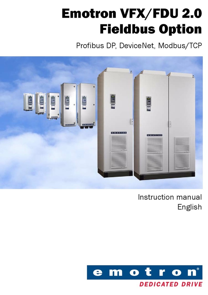
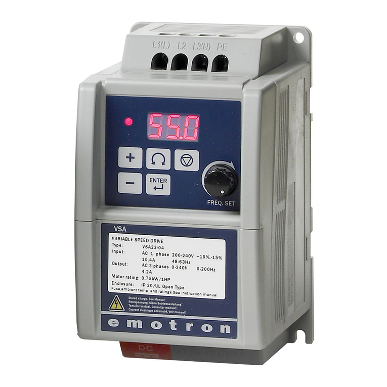
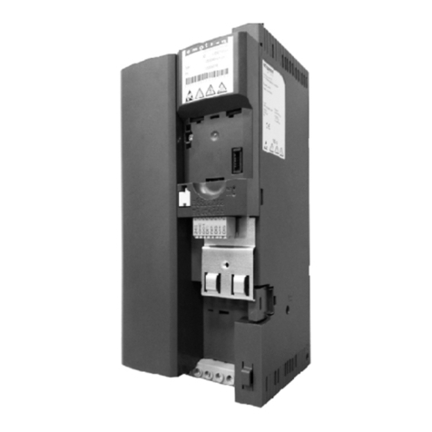
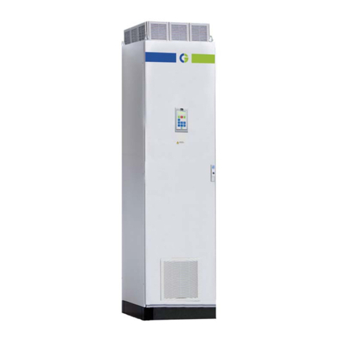
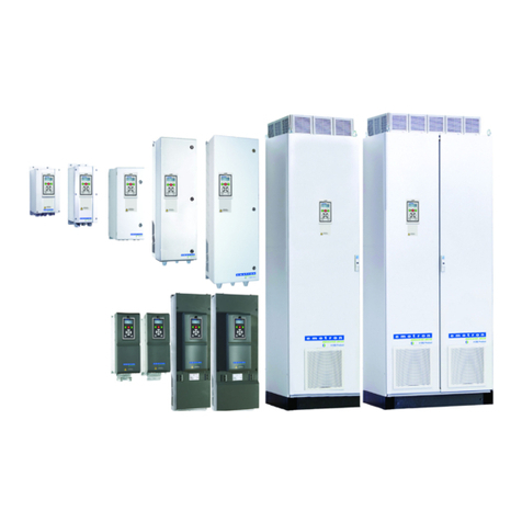
Emotron VFX 2.1 User manual

Emotron VFX 2.1
AC drive
Instruction manual
English
Valid from software version 5.1x


Emotron VFX 2.1
INSTRUCTION MANUAL - ENGLISH
Valid from Software version 5.1x
Document number: 01-7492-01
Edition: r1
Date of release: 2023-01-19
© Copyright CG Drives & Automation Sweden AB 2005 - 2022
CG Drives & Automation Sweden AB retains the right to change
specifications and illustrations in the text, without prior notification.
The contents of this document may not be copied without the explicit
permission of CG Drives & Automation Sweden AB.


CG Drives & Automation 01-7492-01r1 1
Safety Instructions
Congratulations for choosing a product from CG Drives &
Automation!
Before you begin with installation, commissioning or
powering up the unit for the first time it is very important
that you carefully study this Instruction manual.
Following symbols can appear in this instruction or on the
product itself. Always read these first before continuing.
Handling the AC drive
Installation, commissioning, demounting, taking
measurements, etc, of or on the AC drive may only be
carried out by personnel technically qualified for the task.
A number of national, regional and local regulations govern
handling, storage and installation of the equipment. Always
observe current rules and legislation.
Opening the AC drive
Always take adequate precautions before opening the AC
drive. Although the connections for the control signals and
the switches are isolated from the main voltage, do not
touch the control board when the AC drive is switched on.
Incorrect connection
The AC drive is not protected against incorrect connection
of the mains voltage, and in particular against connection of
the mains voltage to the motor outlets U, V and W. The AC
drive can be damaged in this way. Risk for personal injury.
Precautions to be taken with a
connected motor
If work must be carried out on a connected motor or on the
driven machine, the mains voltage must always be
disconnected from the AC drive first. Wait at least 7minutes
before starting work.
Earthing
The AC drive must always be earthed via the mains safety
earth connection.
Earth leakage current
Residual current device (RCD)
compatibility
This product can cause a DC current in the protective
earthing conductor. Where a residual current-operated
protective device (RCD) or a monitoring device (RCM) is
used for protection in case of direct or indirect contact, only
a Type B RCD/RCM is allowed on the supply side of this
product. Use RCD of 300 mA minimum.
NOTE: Additional information as an aid to avoid
problems.
CAUTION!
Failure to follow these instructions can
result in malfunction or damage to the
AC drive.
Warning!
Failure to follow these instructions can
result in serious injury to the user in
addition to serious damage to the AC
drive.
HOT SURFACE!
Failure to follow these instructions can
result in injury to the user.
WARNING!
Always switch off the mains voltage
before opening the AC drive and wait
at least 7 minutes to allow the
capacitors to discharge.
!
CAUTION!
This AC drive has an earth leakage
current which does exceed 3.5 mA AC.
Therefore the minimum size of the
protective earth conductor on the supply side
must comply with the local safety regulations for
high leakage current equipment which means
that according to the standard IEC61800-5-1 the
protective earth connection must be assured by
one of following conditions:
PE conductor cross-sectional area shall for
phase cable size < 16 mm2(6 AWG) be >10 mm2
Cu (16 mm2Al) or use a second PE conductor
with same area as original PE conductor.
For cable size above 16 mm2(6 AWG) but smaller
or equal to 35mm2 (2 AWG) the PE conductor
cross-sectional area shall be at least 16mm2
(6 AWG).
For cables >35 mm2(2 AWG) the PE conductor
cross-sectional area should be at least 50 % of
the used phase conductor.
When the PE conductor in the used cable type is
not in accordance with the above mentioned
cross-sectional area requirements, a separate
PE conductor should be used to establish this.
!

2CG Drives & Automation 01-7492-01r1
EMC Regulations
In order to comply with the EMC Directive, it is absolutely
necessary to follow the installation instructions. All
installation descriptions in this manual follow the EMC
Directive.
Mains voltage selection
The AC drive may be ordered for use with the mains voltage
range listed below.
VFX48: 230-480 V
VFX52: 440-525 V
VFX69: 500-690 V
Voltage tests (Megger)
Do not carry out voltage tests (Megger) on the motor, before
all the motor cables have been disconnected from the AC
drive.
Condensation
If the AC drive is moved from a cold (storage) room to a
room where it will be installed, condensation can occur.
This can result in sensitive components becoming damp. Do
not connect the mains voltage until all visible dampness has
evaporated.
Power factor capacitors for
improving cosϕ
Remove all capacitors from the motor and the motor outlet.
Precautions during Autoreset
When the automatic reset is active, the motor will restart
automatically provided that the cause of the trip has been
removed. If necessary take the appropriate precautions.
Transport
To avoid damage, keep the AC drive in its original
packaging during transport. This packaging is specially
designed to absorb shocks during transport.
IT Mains supply
The AC drives can be modified for an IT mains supply,
(non-earthed neutral), please contact your supplier for
details.
Alarms
Never disregard an alarm. Always check and remedy the
cause of an alarm.
Heat warning
DC-link residual voltage
HOT SURFACE!
Be aware of specific parts on the AC
drive having high temperature.
WARNING!
After switching off the mains supply,
dangerous voltage can still be present
in the AC drive. When opening the AC
drive for installing and/or
commissioning activities wait at least 7 minutes.
In case of malfunction a qualified technician
should check the DC-link or wait for one hour
before dismantling the AC drive for repair.

CG Drives & Automation 01-7492-01r1 3
Contents
Safety Instructions ......................................... 1
Contents.......................................................... 3
1. Introduction..................................................... 7
1.1 Delivery and unpacking ............................................ 7
1.2 Using of the instruction manual ............................... 7
1.2.1 Instruction manuals for optional equipment........... 7
1.3 Warranty .................................................................... 8
1.4 Type code number..................................................... 8
1.5 Standards ................................................................ 10
1.5.1 Product standard for EMC ...................................... 10
1.6 Dismantling and scrapping..................................... 12
1.6.1 Disposal of old electrical and electronic
equipment ............................................................... 12
1.7 Glossary ................................................................... 12
1.7.1 Abbreviations and symbols..................................... 12
1.7.2 Definitions................................................................ 12
2. Mounting ...................................................... 13
2.1 Lifting instructions................................................... 13
2.2 Stand-alone units .................................................... 17
2.2.1 Cooling ..................................................................... 17
2.2.2 Mounting schemes.................................................. 18
2.3 Cabinet mounting.................................................... 25
2.3.1 Cooling ..................................................................... 25
2.3.2 Recommended free space in front of cabinet ...... 25
2.3.3 Mounting schemes, cabinets ................................. 26
3. Installation ................................................... 29
3.1 Before installation................................................... 29
3.1.1 Remove/open front cover ...................................... 29
3.1.2 Remove/open the lower front cover on
Frame size E2, F2 and FA2 (IP20/21)................... 30
3.2 Cable connections for small and medium
frame sizes .............................................................. 30
3.2.1 Mains cables ........................................................... 30
3.2.2 Motor cables............................................................ 33
3.3 Connection of motor and mains cables for
larger frame sizes.................................................... 35
3.3.1 Connection of mains and motor cables on
IP20 modules .......................................................... 38
3.4 Cable specifications ................................................ 39
3.4.1 Stripping lengths ..................................................... 39
3.4.2 Fuse data................................................................. 41
3.4.3 Cable connection data for mains, motor and
PE cables according to IEC ratings ........................ 42
3.4.4 Cable connection data for mains, motor and
PE cables according to NEMA ratings.................... 46
3.5 Thermal protection on the motor ........................... 48
3.6 Motors in parallel .................................................... 48
4. Control Connections.................................... 49
4.1 Control board........................................................... 49
4.2 Terminal connections ............................................. 50
4.2.1 Stand by supply interface (SBS)............................. 51
4.3 Configuration with jumpers and switches ............. 51
4.3.1 Analogue input configuration (S1 - S4).................. 51
4.3.2 RS-485 termination (S5) ........................................ 52
4.4 Connection example ............................................... 53
4.5 Connecting the control signals............................... 54
4.5.1 Cables ...................................................................... 54
4.5.2 Types of control signals .......................................... 56
4.5.3 Screening................................................................. 56
4.5.4 Single-ended or double-ended connection? ......... 56
4.5.5 Current signals ((0)4-20 mA).................................. 57
4.5.6 Twisted cables......................................................... 57
4.6 Connecting options ................................................. 57
5. Getting Started............................................. 59
5.1 Connect the mains and motor cables ................... 59
5.1.1 Mains cables ........................................................... 59
5.1.2 Motor cables............................................................ 59
5.2 Using the function keys .......................................... 60
5.3 Remote control........................................................ 60
5.3.1 Connect control cables ........................................... 60
5.3.2 Switch on the mains ............................................... 60
5.3.3 Set the Motor Data.................................................. 61
5.3.4 Run the AC drive...................................................... 61
5.4 Local control ............................................................ 61
5.4.1 Switch on the mains ............................................... 61
5.4.2 Select manual control............................................. 61
5.4.3 Set the Motor Data.................................................. 61
5.4.4 Enter a Reference Value......................................... 61
5.4.5 Run the AC drive...................................................... 61
6. Applications.................................................. 63
6.1 Application overview ............................................... 63
6.1.1 Cranes...................................................................... 63
6.1.2 Crushers................................................................... 63
6.1.3 Mills.......................................................................... 64
6.1.4 Mixers ...................................................................... 64
7. Main Features .............................................. 65
7.1 Parameter sets........................................................ 65
7.1.1 Define parameter sets............................................ 65
7.1.2 Select and copy parameter set .............................. 65
7.1.3 One motor and one parameter set ........................ 66
7.1.4 One motor and two parameter sets....................... 66
7.1.5 Two motors and two parameter sets ..................... 66
7.1.6 Autoreset at trip ...................................................... 66
7.1.7 Reference priority.................................................... 67
7.1.8 Preset references.................................................... 67
7.2 Remote control functions ....................................... 67
7.2.1 Default settings of the Run/Stop/Enable/
Reset functions ....................................................... 67
7.3 Performing an Identification Run........................... 70
7.4 Using the Control Panel Memory............................ 70
7.5 Load Monitor and Process Protection [400] ......... 71
7.5.1 Load Monitor [410]................................................. 71
8. EMC and standards...................................... 73
8.1 EMC standards........................................................ 73
8.2 Stop categories and emergency stop .................... 73

4CG Drives & Automation 01-7492-01r1
9. Communication ........................................... 75
9.1 Modbus RTU ............................................................ 75
9.2 Parameter sets........................................................ 75
9.3 Motor data ............................................................... 76
9.4 Start and stop commands ...................................... 76
9.5 Reference signal ..................................................... 76
9.5.1 Process value .......................................................... 76
9.6 Description of the EInt formats .............................. 77
10. Operation via the Control Panel ................. 79
10.1 General .................................................................... 79
10.2 Control panel with 4-line display ............................ 79
10.2.1 The display............................................................... 79
10.2.2 Menu [100] Start Window ...................................... 81
10.2.3 Editing mode............................................................ 81
10.2.4 Fault logger.............................................................. 82
10.2.5 Real Time clock ....................................................... 82
10.2.6 LED indicators ......................................................... 82
10.2.7 Control keys ............................................................. 82
10.2.8 The Toggle and Loc/Rem Key ................................ 83
10.2.9 Function keys .......................................................... 84
10.3 The menu structure................................................. 84
10.3.1 The main menu ....................................................... 85
10.4 Programming during operation .............................. 85
10.5 Editing values in a menu ........................................ 85
10.6 Copy current parameter to all sets ........................ 86
10.7 Programming example............................................ 86
11. Functional description ................................ 87
11.1 Menus ...................................................................... 87
11.1.1 Description of menu table layout........................... 87
11.1.2 Resolution of settings ............................................. 88
11.1.3 1st Line [110].......................................................... 88
11.2 Main Setup [200].................................................... 89
11.2.1 Operation [210]....................................................... 89
11.2.2 Motor Data [220] .................................................... 93
11.2.3 Motor Protection [230] ........................................... 99
11.2.4 Parameter Set Handling [240] ............................. 102
11.2.5 Trip Autoreset/Trip Conditions [250]................... 105
11.2.6 Serial Communication [260] ................................ 110
11.2.7 Wireless [270] ....................................................... 114
11.3 Process and Application Parameters [300] ........ 116
11.3.1 Set/View Reference Value [310] ......................... 116
11.3.2 Process Settings [320] ......................................... 117
11.3.3 Start/Stop settings [330] ..................................... 121
11.3.4 Mechanical brake control ..................................... 124
11.3.5 Speed [340]........................................................... 128
11.3.6 Torques [350]........................................................ 130
11.3.7 Preset References [360] ...................................... 132
11.3.8 PI Speed Control [370] ......................................... 134
11.3.9 PID Process Control [380] .................................... 135
11.3.10 Pump/Fan Control [390] ...................................... 138
11.3.11 Crane Option [3A0] ............................................... 143
11.4 Load Monitor and Process Protection [400] ....... 145
11.4.1 Load Monitor [410] ............................................... 145
11.4.2 Process Protection [420]...................................... 149
11.4.3 Trip text [430]........................................................ 150
11.5 I/Os and Virtual Connections [500]..................... 150
11.5.1 Analogue Inputs [510] .......................................... 150
11.5.2 Digital Inputs [520] ............................................... 155
11.5.3 Analogue Outputs [530] ....................................... 157
11.5.4 Digital Outputs [540] ............................................ 160
11.5.5 Relays [550] .......................................................... 162
11.5.6 Virtual Connections [560] .................................... 163
11.6 Logical Functions and Timers [600] .................... 164
11.6.1 Comparators [610] ............................................... 164
11.6.2 Analogue Multiplexer [620].................................. 170
11.6.3 Not Gate [630] ...................................................... 171
11.6.4 Logic output [640] ................................................ 172
11.6.5 Timers [650].......................................................... 174
11.6.6 Flip flops [660] ...................................................... 176
11.6.7 Counters [670]...................................................... 178
11.6.8 Clock Logic [680] .................................................. 180
11.7 View Operation/Status [700] ............................... 181
11.7.1 Operation [710]..................................................... 181
11.7.2 Status [720] .......................................................... 183
11.7.3 Stored values [730] .............................................. 186
11.8 View Trip Log [800] ............................................... 187
11.9 System Data [900]................................................ 189
11.9.1 VSD Data [920] ..................................................... 189
11.9.2 Real Time clock ..................................................... 191
11.9.3 Inspection [940].................................................... 191
11.9.4 Service cont [950]................................................. 192
12. Troubleshooting, Diagnoses and
Maintenance ..............................................193
12.1 Trips, warnings and limits..................................... 193
12.2 Trip conditions, causes and remedial action ...... 194
12.2.1 Technically qualified personnel............................ 195
12.2.2 Opening the AC drive ............................................ 195
12.2.3 Precautions to take with a connected motor ...... 195
12.2.4 Autoreset Trip ........................................................ 195
12.3 Maintenance ......................................................... 200
13. Options........................................................ 201
13.1 Control panel ......................................................... 201
13.2 External control panel kits.................................... 201
13.2.1 Control panel kit, including blank panel.............. 201
13.2.2 Control panel kit, including control panel............ 201
13.3 Handheld Control Panel 2.0................................. 202
13.4 Gland kits............................................................... 202
13.5 EmoSoftCom.......................................................... 202
13.6 EmoDrive App ........................................................ 202
13.7 Brake chopper....................................................... 203
13.8 I/O Board ............................................................... 204
13.9 Encoder.................................................................. 204
13.10 PTC/PT100 ............................................................ 204
13.11 Crane option board ............................................... 205
13.12 Communication options........................................ 205
13.13 Safe Torque Off (STO) ........................................... 205
13.14 EMC filter class C1/C2 ......................................... 205
13.15 Output chokes ....................................................... 205
13.16 Liquid cooling ........................................................ 205
13.17 Top cover for IP20/21 version ............................. 206
13.18 Other options......................................................... 206
13.19 AFE - Active Front End........................................... 206
CG Drives & Automation 01-7492-01r1 5
14. Technical Data........................................... 207
14.1 Electrical specifications related to model ........... 207
14.2 General electrical specifications.......................... 214
14.3 Operation at higher temperatures ....................... 215
14.3.1 Possible derating................................................... 215
14.4 Dimensions and Weights...................................... 216
14.5 Environmental conditions..................................... 219
14.6 Fuses and glands .................................................. 220
14.6.1 According to IEC ratings........................................ 220
14.6.2 Fuses according to NEMA ratings ........................ 224
14.7 Control signals....................................................... 225
15. Menu List.................................................... 227
16. EcoDesign product information per
EU Directive 2019/1781 ..........................257
16.1 EcoDesign data for 400 V - IP20 and IP54
drive units .............................................................. 257
16.2 EcoDesign data for 400 V - IP54 drive units ....... 258
16.3 EcoDesign data for 525 V - IP54 drive units ....... 259
16.4 EcoDesign data for 690 V - IP20 and IP54
drive units .............................................................. 260
Index ........................................................... 261

6CG Drives & Automation 01-7492-01r1

CG Drives & Automation 01-7492-01r1 Introduction 7
1. Introduction
Emotron VFX is intended for controlling the speed and
torque of standard three phase asynchronous electrical
motors. The AC drive (Frequency converter) is equipped
with direct torque control which uses built-in digital signal
processor - DSP, giving the AC drive the capability of high
dynamic performance even at very low speeds without using
feedback signals from the motor. Therefore the inverter is
designed for use in high dynamic applications where low
speed high torque and high-speed accuracy are demanded.
In “simpler” application such as fans or pumps, the VFX
direct torque control offers other great advantages such as
insensitivity to mains disturbances or load shocks. Several
options are available, listed in chapter 13. page 201, that
enable you to customize the AC drive for your specific
needs.
Users
This instruction manual is intended for:
• installation engineers
• maintenance engineers
• service engineers
Motors
The AC drive is suitable for use with standard 3-phase
asynchronous motors. Under certain conditions it is possible
to use other types of motors. Contact your supplier for
details.
1.1 Delivery and unpacking
Check for any visible signs of damage. Inform your supplier
immediately of any damage found. Do not install the AC
drive if damage is found.
Check that all items are present and that the type number is
correct.
1.2 Using of the instruction
manual
Within this instruction manual the abbreviation “AC drive”
is used to indicate the complete variable speed drive as a
single unit.
Check that the software version number on the first page of
this manual matches the software version in the AC drive.
See section 11.9.1 page 189.
With help of the index and the table of contents it is easy to
track individual functions and to find out how to use and set
them.
The Quick Setup Card can be put in a cabinet door, so that
it is always easy to access in case of an emergency.
1.2.1 Instruction manuals for
optional equipment
In the following table we have listed available options and
the name of the Instruction manual or data sheet/
Instruction plus document number. Further in this main
manual we are often referring to these instructions.
NOTE: Read this instruction manual carefully before
starting installation, connection or working with the
AC drive.
Ta b l e 1 Av a i l a b l e o p tions and documents
Option Valid instruction manual/
document number
I/O board I/O board 2.0, instruction
manual / 01-5916-01
Encoder board Emotron Encoder board
2.0, Instruction manual /
01-5917-01
PTC/PT100 board PTC/PT100 board 2.0,
instruction manual /
01-5920-01
CRIO board (VFX) Emotron AC Drive Crane
option 2.0, Instruction
manual
Crane interface (VFX)
Fieldbus - Profibus
Fieldbus Option,
Instruction manual /
01-3698-01
Fieldbus - DeviceNet
Fieldbus - CANopen
Ethernet - Modbus TCP
Ethernet - EtherCAT
Ethernet - Profinet IO 1-port
Ethernet - Profinet IO 2-port
Ethernet - EtherNet/IP 2-port
RS232/RS485 isolated
Emotron isolated
RS232 / 485 2.0 option
Instruction manual /
01-5919-01
Control panel kit, Incl blank
panel Emotron FDU/VFX 2.0
External Control Panel,
instruction manual / 01-
5928-01
Control panel kit, Incl control
panel
Handheld Control Panel
HCP2.0
Emotron HCP 2.0,
instrucion manual / 01-
5925-01
OSTO_100 option board
Emotron OSTO_100
Safe Torque Off (STO)
Instruction manual /
01-7513-11
Overshoot clamp Overshoot clamp
Datasheet/Instruction /
01-5933-11
Liquid cooling Emotron FDU/VFX 2.0
Liquid Cooling, instruction
manual / 01-4636-01
Output choke Output coils
Datasheet/Instruction /
01-3132-11
AFE- Active front end
Emotron VFX/FDU 2.0
AFE- Active Front End
option, Instruction manual
/ 01-5386-01
EmoDrive App EmoDrive App Instruction
manual / 01-7776-01

8Introduction CG Drives & Automation 01-7492-01r1
1.3 Warranty
The warranty applies when the equipment is installed,
operated and maintained according to instructions in this
instruction manual. Duration of warranty as per contract.
Faults that arise due to faulty installation or operation are
not covered by the warranty.
1.4 Type code number
Fig. 1 gives an example of the type code numbering used on
all AC drives. With this code number the exact type of the
drive can be determined. This identification will be required
for type specific information when mounting and installing.
The code number is located on the product label, on the
unit.
New type code for all FDU/VFX drive sizes (002-3K0),
valid from 2021-01-01(serial no from:
PPPPRR2101SSSS*).
Fig. 1 Type code number
Type code VFX 48 -017 -20 C E – – – A – N N N N A N – – A
Position No 1 2 3 4 5 6 7 8 9 1011121314151617181920
Position
for 002-3K0 Configuration
1 AC drive type VFX
2 Supply voltage
48=480 V mains
52=525 V mains
69=690 V mains
3 Rated current (A) continuous
-002=2.0 A
-
-3K0=3000 A
4 Protection class
20=IP20 - Intended for mounting inside a cabinet
21=IP21 - Intended for wall-mounting
54=IP54 - Intended for wall-mounting
5 Control panel
–=Blank panel
D=4-line Control panel, standard IP2X/54
E=4-line Control panel with Bluetooth (option IP2X/54)
F=4-line Control panel with WiFi (option IP2X/54)
6 EMC option
E=Standard EMC (Category C3)
F=Extended EMC (Category C2)
I=IT-Net
7 Brake chopper option
–=No chopper
B=Chopper built in
D=DC+/- interface
8 Stand-by power supply option –=No SBS (24V input included in Control board 2.1)
S=SBS included (code not used with Control board 2.1)
9 Safe Torque Off option –=No Safe Torque Off
O=Safe Torque Off included
10 Brand label A=Standard
11 Coated boards, option –=Standard, not coated boards IP54
V=Coated boards, option IP54 (standard IP2X)

CG Drives & Automation 01-7492-01r1 Introduction 9
*) Serial no coding: PPPPRRYYWWSSSS
PPPP = Manufacturing plant
RR = Product revision no
YY = Manufacturing year
WW = Manufacturing week
SSSS = Serial no
E.g. 18410121010001
12 Option position 1
N=No option
C=Crane I/O (max. 1)
E=Encoder (max. 1)
P=PTC/PT100 (max. 2)
I=Extended I/O (max. 3)
13 Option position 2
14 Option position 3
15 Option position, communication
N= No option
D= DeviceNet
P= Profibus
S= RS232/485
M= Modbus/TCP 1-port
H= Modbus/TCP 2-port
E= EtherCAT
A= Profinet IO 1-port
B= Profinet IO 2-port
G= EtherNet/IP 2-port
C= CANopen
16 Software type A= Standard software
17 Motor PTC.
(Only valid for 002-105/B-D2(69)) N= No option
P= PTC
18 Gland kit.
(Only valid for 002-074/IP54) –= Glands not included
G= Gland kit included
19 Approval/certification
–= CE approved
D= Marine DNV Product certificate (above 100 kW) + CE approved
M= Marine version + CE approved
U=UL/cUL approved
20 Painted AC drive A=Standard paint
Position
for 002-3K0 Configuration

10 Introduction CG Drives & Automation 01-7492-01r1
1.5 Standards
The AC drives described in this instruction manual comply
with the standards listed in table 2. For the declarations of
conformity and manufacturer’s certificate, contact your
supplier for more information or visit www.emotron.com/
www.cgglobal.com.
1.5.1 Product standard for EMC
Product standard EN IEC 61800-3:2018.
First Environment (Extended EMC) as environment that
includes domestic premises. It also includes establishments
directly connected without intermediate transformers to a
low voltage power supply network that supplies buildings
used for domestic purposes.
Category C2: Power Drive System (PDS) of rated
voltage<1.000 V, which is neither a plug in device nor a
movable device and, when used in the first environment, is
intended to be installed and commissioned only by a
professional.
Second environment (Standard EMC) includes all other
establishments.
Category C3: PDS of rated voltage <1.000 V, intended for
use in the second environment and not intended for use in
the first environment.
Category C4: PDS or rated voltage equal or above 1.000 V,
or rated current equal to or above 400 A, or intended for use
in complex systems in the second environment.
The AC drive complies with the product standard
EN IEC 61800-3:2018 (Any kind of metal screened cable
may be used). The standard AC drive is designed to meet the
requirements according to category C3, for a motor cable
length of maximum 80 m.
By using the optional “Extended EMC” filter the AC drive
fulfils requirements according to category C2.
WARNING!
In a domestic environment this product
may cause radio interference, in which
case it may be necessary to take adequate
additional measures.
WARNING!
The standard AC drive, complying with
category C3, is not intended to be used on
a low-voltage public network which
supplies domestic premises; radio
interference is expected if used in such a
network. Contact your supplier if you need
additional measures.

CG Drives & Automation 01-7492-01r1 Introduction 11
Ta b l e 2 St a n d a r d s
Market Standard Description
European
EMC Directive 2014/30/EU
Low Voltage Directive 2014/35/EU
WEEE Directive 2012/19/EU
Ecodesign Directive 2009/125/EC
RoHS II Directive 2011/65/EU
RED Directive 2014/53/EU
Great Britain (England,
Scotland, Wales)
UKCA
ECR Electromagnetic Compatibility Regulations - 2016/1091
EESR Electrical Equipment (Safety) Regulations - 2016/1101
EERPEI Ecodesign for Energy-Related Products and Energy Information Regulation -
2021/745
RUCHSEEE Restriction of the Use of Certain Hazardous Substances in Electrical and
Electronic Equipment - 2012/3032
RER Radio Equipment Regulations - 2017/1206
All
EN 60204-1:2018 Safety of machinery - Electrical equipment of machines
Part 1: General requirements.
EN IEC 61800-3:2018 Adjustable speed electrical power drive systems
Part 3: EMC requirements and specific test methods.
EMC Directive: Declaration of Conformity and CE marking
EN(IEC)61800-5-1:2007
+ A1:2017 + A11:2021
Adjustable speed electrical power drive systems Part 5-1.
Safety requirements - Electrical, thermal and energy.
Low Voltage Directive: Declaration of Conformity and CE marking
IEC 60721-3-3:2019
Classification of environmental conditions. Air quality chemical vapours, unit
in operation. Chemical gases 3C2, Solid particles 3S2.
Optional with coated boards
Unit in operation. Chemical gases Class 3C3, Solid particles 3S2.
EN 50581:2012 Restriction of hazardous substances
North & South
America
ULC508C UL Safety standard for Power Conversion Equipment
USL USL (United States Standards - Listed) complying with the requirements of
UL508C Power Conversion Equipment
UL 840 UL Safety standard for Power Conversion Equipment.
Insulation coordination including clearances and creepage distances for
electrical equipment.
CNL CNL (Canadian National Standards - Listed) complying with the requirements
of CAN/CSA C22.2 No. 14-10 Industrial Control Equipment.
Russian EAC For all sizes.

12 Introduction CG Drives & Automation 01-7492-01r1
1.6 Dismantling and
scrapping
The enclosures of the drives are made from recyclable
material as aluminium, iron and plastic. Our AC-drives
comply to RoHS II directive, and contain electronic waste
(e-waste). Any local or national regulations in force for the
disposal and recycling of e-waste must be complied with.
1.6.1 Disposal of old electrical and
electronic equipment
This symbol on the product or on its packaging indicates
that this product shall be taken to the applicable collection
point for the recycling of electrical and electronic
equipment. By ensuring this product is disposed of correctly,
you will help prevent potentially negative consequences for
the environment and human health, which could otherwise
be caused by inappropriate waste handling of this product.
The recycling of materials will help to conserve natural
resources. For more detailed information about recycling
this product, please contact the local distributor of the
product.
1.7 Glossary
1.7.1 Abbreviations and symbols
In this manual the following abbreviations are used:
1.7.2 Definitions
In this manual the following definitions for current, torque
and frequency are used:
Table 3 Abbreviations
Abbreviation/
symbol Description
DSP Digital signals processor
AC drive Frequency converter
PEBB Power Electronic Building Block
IGBT Insulated Gate Bipolar Transistor
CP Control panel, the programming and
presentation unit on the AC drive
HCP Handheld control panel (option)
EInt Communication format
UInt Communication format (Unsigned integer)
Int Communication format (Integer)
Long Communication format
SELV Safety Extra Low Voltage
The function cannot be changed in run
mode
Table 4 Definitions
Name Description Quantity
IIN Nominal input current of AC drive ARMS
INOM Nominal output current of AC drive ARMS
IMOT Nominal motor current ARMS
PNOM Nominal power of AC drive kW
PMOT Motor power kW
TNOM Nominal torque of motor Nm
TMOT Motor torque Nm
fOUT Output frequency of AC drive Hz
fMOT Nominal frequency of motor Hz
nMOT Nominal speed of motor rpm
ICL Maximum output current ARMS
Speed Actual motor speed rpm
Torque Actual motor torque Nm
Sync
speed Synchronous speed of the motor rpm

CG Drives & Automation 01-7492-01r1 Mounting 13
2. Mounting
This chapter describes how to mount the AC drive.
Before mounting it is recommended that the installation is
planned out first.
• Be sure that the AC drive suits the mounting location.
• The mounting site must support the weight of the AC
drive.
• Will the AC drive continuously withstand vibrations
and/or shocks?
• Consider using a vibration damper.
• Check ambient conditions, ratings, required cooling air
flow, compatibility of the motor, etc.
• Know how the AC drive will be lifted and transported.
2.1 Lifting instructions
Recommended for IP 54 AC drive
models -090 to -365
Fig. 2 Lifting IP 54 AC drive model -090 to -365.
Recommended lifting points for IP 20
modules size H/H69 and up
Fig. 3 Lifting holes.
Fig. 4 Lifting holes with lifting shackles.
Note: IP20 units are intended for cabinet mounting.
Note: To prevent personal risks and any damage to
the unit during lifting, it is advised that the lifting
methods described below are used.
Load: 56 to 95 kg
(123 - 202 lbs)
1 Hole diameter =17 mm (x2)
Note: Lifting shackles not included in the drive
delivery.
1

14 Mounting CG Drives & Automation 01-7492-01r1
Recommended for AC drive cabinet
models -430 to - 3K0
Transport by crane
All enclosures are suitable for transporting by crane, either as
free-standing enclosures or as bayed suites.
With eyebolts
Individual enclosures are safely transported using the
eyebolts.
For symmetrical loads, the following maximum permissible
overall loads apply:
Fig. 5 Lifting enclosures with eyebolts.
With combination angle
For the enclosure combination with internal baying brackets
and combination angles shown here, the load capacity with a
cable pull angle of 60° is as follows:
F1 = 7000 N
F2 = 7000 N
Fig. 6 Enclosure combination with internal brackets.
Note: To prevent personal risks and any damage to the
unit during lifting, it is advised that the lifting methods
described below are used.
Cable/chain angle A Permitted load (F)
45 ° 4 800 N (1080 lbf)
60 ° 6 400 N (1439 lbf)
90 ° 13 600N (3057 lbf)
Note: Calculated load F as F [N] = m [kg] x 9.81.
F
F
F
F
F
F
A
F1 F2

CG Drives & Automation 01-7492-01r1 Mounting 15
For the enclosure combination with internal baying brackets
and combination angles shown here, the load capacity with a
cable pull angle of 60° is as follows:
F1 = 7000 N
F2 = 14000 N
F3 = 7000 N
Fig. 7 Enclosure combination with internal brackets.
F1 F2 F3

16 Mounting CG Drives & Automation 01-7492-01r1
Transport by fork-lift truck
When transporting individual and bayed enclosures, please
take care to ensure that the base/plinth trim panels are fitted,
and loads are restricted to the immediate vicinity of the base/
plinth corner pieces.
Transport of individual enclosures
Fig. 8 Transport of individual enclosure with fork-lift truck.
Transport of bayed enclosure suites
For the enclosure combination with internal baying brackets
the following load capacities are supported:
Fig. 9 Transport of enclosure combination with fork-lift truck.
FF
FFF
Max. 15000 N
Max. 15000 N
Max. 7000 N
Max. 14000 N
Max. 7000 N
Table of contents
Other Emotron DC Drive manuals

Emotron
Emotron FlowDrive Emotron FLD48 User manual

Emotron
Emotron EMX-D User manual

Emotron
Emotron VS30 Guide

Emotron
Emotron VFX 2.0 User manual

Emotron
Emotron FDU Series User manual

Emotron
Emotron VFX 2.0 User manual

Emotron
Emotron VSA Series User manual

Emotron
Emotron EMX-R Series User manual

Emotron
Emotron EMX-R-15S User manual

Emotron
Emotron FDU 2.0 User manual