Endecotts EFL 2000/1 User manual

The EFL 2000/1 & 2 User Guide
Test Sieve Shaker
_______________________________________________
ISSUE 04-02 Contents
Description Page 1
Setting Up: 2 -8
Unpacking 2
Assembly 3
Clamping Assembly 4
Electrical Connections 5
Sieve Stacking 6–8
Operating Instructions 9 - 11
Position of Controls 9
Function of Controls 10 - 11
MainsInlet 10
Mains Switch 10
Mains Connected Indicator 10
Mains Power Indicator 10
Process Timer 10 - 11
Fuse 11
Blanking Plug 11
Operation 12
WetSieving 13
Wet Sieving Adaptor Kit 14
Maintenance
Cleaning 15
FuseReplacement 15
Drive Unit 16 -18
Removal 16
Motor Removal 16 -17
Assembly of Drive Unit 17 -18
Replacement 18

_______________________________________________________
Contents
Eccentric Cam 19
Adjustment of Clearance 20
Specification 21
General Advice 22

Description
____________________________________
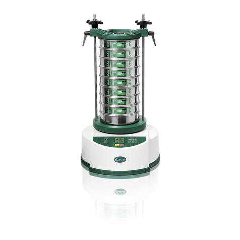
The Endecotts EFL 2000 is a vibrating shaker that is used to carry out
sieve tests in conjunction with sieve stacks for particle sizing of various
material samples.
It is based on a rotary motor with an eccentric cam drive with special
non-metallic laminated springs that are set at a calculated angle to
provide a horizontal twist, as well as a vertical movement to carry out
efficient sieve tests.
The EFL 2000 range are fixed amplitude shakers.
An incremental timer provides a range of pre-set
and repeatable sieve test run times.
The EFL is fully EMC and LVD
compliant and complies with all
relevant European directives.
- 1 -

Unpacking
________________________________________________
The shaker should be set up according to the following procedure and
the diagram opposite. The Internal packing and following list of items
should be removed from the case and checked before the EFL 2000 is
removed.
1 off Test Sieve Shaker EFL 2000
2 off M12 Plated Lock Nuts
2 off M12 Plated Plain Washers
2 off Clamping Handwheels
2 off Large Plain Clamp Washers
2 off Clamping Handwheels
1 off Clamp Plate Assembly complete
with Locking Assemblies
4 off Anti-Vibration Mounts
4 off M10 Large Washers
1 off Mains Cable
1 off Instruction Manual
EFL 2000/1
2 off Short Clamp Rods SA 564/3
2 off Standard Clamp Rods SA 564/1
EFL 2000/2
2 off Short Clamp Rods SA 564/3
2 off Long Clamp Rods SA 564/2
Keeping top opening of packing case uppermost unscrew transit bolts
from underside of case (placing blocks under packing will assist
this operation). Lift the shaker from packing case carefully. The anti-
vibration mounts should be screwed into the four tapped holes provided
on the underside of the underside of the machine and adjust the feet to
level the shaker then tighten the lock nuts.
- 2 -

Setting Up
________________________________________________
Assembly
The machine should be positioned on a level rigid and robust floor
suitable for the operation of the sieve shaker, (placing the shaker on a
level surface ensures the even distribution of the sample over the sieves
and ensures machine stability).
Take Care as the shaker weighs 83 Kg
CLAMP HAND CLAMP PLATE ASSEMBLY
WHEELS
LARGE PLAIN LOCKING HANDLE
CLAMP WASHERS LEVERS
SIEVE STACK CLAMP RODS
M12 PLATED LOCK
M12 PLATED WASHER
CONTROLPANEL
- 3 -

Setting Up
________________________________________________
Clamping Assembly
Fit one M12 nut and washer onto each clamp rod selected for use, then
screw the pair of clamp rods into the location plate and tighten the
locknuts.
Place the two large plain washers over the 20mm threads of the clamp
sleeves. These can be seen protruding vertically from the two side lugs
on the clamp plate. Screw the two handwheels loosely onto the 20mm
threads, leave a gap of 3mm between the large washer and the
handwheel face. Do not tighten right down at this point.
See Diagram below:
- 4 -

Setting Up
________________________________________________
Electrical Connections
Ensure that the voltage and frequency on the Rating Label, at the rear of
the shaker correspond with the local electrical mains supply. If there is
any discrepancy, please consult your supplier or a qualified electrician.
Do Not Connect to any other supply other than that stated
on the Nameplate
Important – This equipment must be connected to mains earth
The EFL sieve shaker is provided with a detachable 2 metre long mains
cable which has an IEC moulded connector at the shaker end and plug
suitable for connecting to the local mains supply. Certain models may
be supplied with a fused plug. In the event of failure the fuse must be
replaced with a fuse of identical rating.
- 5 -

Setting Up
________________________________________________
Sieve Stacking
The EFL 2000 shakers accommodate up to the following number of
sieves in a stack plus the required lid and receiver:
Model: Height: 300mm/12 inch 200mm/8 inch 100mm/3
inch
EFL Full Not Applicable 8 12
2000/1 Half Not Applicable 18 24
EFL Full 6 12 16
2000/2 Half Not Applicable 24 32
All sieve stacks require the necessary lid and receiver.
The recesses in the location casting will accept the following sieve
diameters.:
EFL 2000/1:
200mm/8 inch, 150mm/6 inch, 100mm/4 inch or 3 inch
EFL 2000/2:
300mm/12 inch, 200mm/8 inch, 150mm/6 inch, 100mm/4 inch or 3
inch
Place the receiver centrally on the location casting in the appropriate
recess. Stack the required sieves on top of the receiver. Put the samples
in the top sieve and fit the lid.
- 6 -

Setting Up
________________________________________________
Sieve Stacking
Align the locking assemblies in 1.
the two side lugs of the clamp
5mm
plate with the round clamp rods.
Slide the clamp plate down
squarely onto the lid at the top of
the sieve stack.
Ensure that the clamping 2.
handwheels at the top are loose
and the locking assemblies are
fully pushed down. There should
be a 5mm gap between the large
plain washer and the face of the
handwheel.
Place one hand on the top of 3.
the clamp plate and hold
square while locking one side
handle lever. Repeat for the
opposite side handle lever.
- 7 -
.

Setting Up
________________________________________________
Sieve Stacking
The side handle levers can be 4.
set vertically downwards by
pressing on the Red button
and pulling the handle
outwards to release. Turn the
handle to a safe, convenient
angle downwards and release
to engage the teeth.Screw the
two clamping handwheels
down simultaneously to ensure the clamping plate is square. Continue
until the handwheels are tight against the internal stop. Hand tightness
must be exerted so that the assembly does not loosen during vibration.
The locking side handle levers and clamping handwheels must be
tightened sufficiently to ensure that the sieves and receiver are clamped
securely during operation. Damage may occur if the shaker is allowed
to operate with a loose clamping plate.
- 8 -

Operating Instructions
________________________________________________
Position of Controls
Operators should be familiar with, and fully understand the controls and
indicators before operating the machine. This should be done in
conjunction with the diagram below:
CLAMP HAND CLAMP PLATE
WHEELS
SIDE HANDLE
LEVERS
SIEVE STACK
ROUND CLAMP
RODS
4. Power Indicator RECEIVER
3..Mains Connected
indicator, 5.ProcessTimer
Green l.e.d
6. Fuse
2..Mains Switch 1.Mains Inlet
(at rear) (at rear)
7.Blanking Plug
(at rear)
- 9 -

Operating Instructions
________________________________________________
Function of Controls
1. Mains Inlet Mains inlet with integral line filter. Ensure
the IEC connector on the mains lead is pushed fully into the
mains inlet.
2. Mains Switch This controls the electrical power on the
equipment. The side marked 1 is On and the side marked O is
Off.
3. Mains Connected Indicator This indicates electrical
power is connected to the equipment, even though the Mains
switch (2) is in the OFF position. The l.e.d. is illuminated when
the IEC connector is pushed fully into the inlet and power is
switched on at the local outlet. If the l.e.d. fails to light with the
local outlet switch in the On position then a Fuse (6) has blown
or power is not present at the mains.
4. Mains Power Indicator This l.e.d indicates that power has
been switched ON at the mains switch (2). The shaker will
operate when the appropriate actions are taken.
5. Process Timer This is a mechanical 0-60 minute timer
which also provides continuous running (for settings of less
than 15 minutes rotate the knob past the 15 minute mark and
then back to the desired setting). Operating periods are
increased by rotating clockwise and decreased by rotating
anti-clockwise (the timer will commence timing down as soon
as the knob is released, regardless of electrical power being
connected or not).
- 10 -

Operating Instructions
________________________________________________
Function of Controls
When the knob is turned anti-clockwise from the Off position
to the continuous running mark ‘׀’ the shaker will continue
running until the knob is returned to the Off position.
Turning timer knob clockwise
allows the EFL to run for
1min to 60min
TIME mins
l
0
5
OF
I
10
55
15
Turning timer knob
50
anti-cockwise allows
20
the EFL to run
25
45
continuously
30
35
40
F
60
6. Fuse This is an anti-surge, 1¼ inch ceramic fuse which
protects the electrical components within the equipment. It is
important that the recommended current rating is not exceeded
(5 Amperes for 230 volts, 10 Amperes for 110 volts) and the
fuse is replaced with the same type and size. If the fuse blows
after replacement then a fault exists in the equipment.
7. Blanking Plug This is removed and the threaded hole used
as a spillage outlet drain for wet sieving applications. An
optional wet sieving kit is available, and may be purchased
separately. The kit includes a nylon hosetail for connecting a
hosetail.
- 11 -

Operating Instructions
________________________________________________
Operation
1. Plug the mains lead into Mains Inlet (1) and into a power supply
socket.
2. Place sieves onto the shaker as described in Sieve Stacking.
3. Switch the power on at the power supply socket. The green l.e.d.
(Mains) will be energized.
4. Switch on the Mains Switch (2). The green l.e.d. (Power) will be
energized.
5. Set Process Timer (5) to required sieving time. The equipment will
immediately start and automatically switch off upon completion of
the set time.
NOTE: The shaker can be stopped at any time by turning the
Process Timer knob anti-clockwise to ‘0’. Unscrew the two
clamping handwheels and the two side handle levers on the clamp
plate. Slide the clamp plate up the rods to remove. The nest of
sieves may now be removed and the quantity of the sample on each
sieve analysed.
Take Care that there are no loose sieves on the shaker !
Do not attempt to remove the sieves before the shaker has
come to a halt
Do not unscrew clamping handwheels or side handle lever
while the shaker is in operation
- 12 -

Wet Sieving
________________________________________________
SAFETY NOTICE
WET SIEVING WITH ENDECOTTS SHAKERS
All shakers are electrically operated and it is therefore important to
ensure that the liquid used in wet sieving operations NEVER comes
into contact with the shaker mechanism or input terminals.
Endecotts machines are supplied with a spillage drain for minor spills.
The drain is not intended to be used for overflows or external water
sprays.
This Wet Sieving accessory is supplied for use with Endecotts Test
Sieve Shakers and should only be used by qualified personnel.
It is recommended that the mains power supply is via a residual current
device on a miniature circuit breaker (Power Breaker).
If there is any doubt with respect to the use of this equipment, contact a
qualified electrician IMMEDIATELY
Extreme care should be taken to avoid contact with the shaker, or
any electrical part of supply in operation at any time.
In the event that water spills into the shaker
DO NOT TOUCH THE SHAKER.
With dry hands switch of the supply at the mains and disconnect the
mains supply.
The shaker should be allowed to dry out thoroughly and examined by
qualified personnel before further use.
Should wet sieving be a routine procedure then consideration should be
given to the possible use of a remote controlled system.
CAUTION
THE SHAKER MUST BE CONNECTED TO MAINS EARTH
WHEN WET SIEVING
- 13 -

Wet Sieving Adaptor Kit
__________________________________
The wet sieving adapter kit is supplied as an optional extra for 8” or
200mm diameter sieves and should be ordered separately.
The wet sieving kit consists of the following items:
1 off Special Wet Sieving Clamp Plate
1 set ‘O’ Ring Seals. One required for each sieve in the
stack.
I off Special Wet Sieving Receiver.
(Specify for 200mm or 8 in. diameter sieves.)
1 off Nylon Hosetail.
The Blanking Plug (12) at the rear must be removed and the nylon
hosetail fitted. The hosetail must have a suitable length of hose
fitted to drain into a convenient drainage point. The ‘O’ ring seals
are fitted on the outside of the bottom rim of each sieve so that
when the sieves are stacked onto each other they form a seal. The
bottom sieve is stacked on the special receiver with a spout. Fit a
suitable length of hose to the spout to drain into a convenient
drainage point. The clamp plate is usually supplied with the rose
reversed to avoid damage. Undo and reverse, so that the rose head
is on the inside. Remove the lid from the sieve stack and replace the
standard clamp plate with the wet sieving clamp plate. Fit a suitable
length of hose to the inlet of the rose on the clamp plate and
connect to the fluid supply with flow regulation.
- 14 -

Maintenance
__________________________________
The Endecott’s EFL sieve shaker is maintenance free other than
keeping external surfaces clean.
Cleaning Cleaning must always be done with the
mains power switched off and the cable disconnected. Cleaning
should be done by wiping with a soft cloth, dampened in a dilution
of water and a mild detergent.
Do not use any solvent for cleaning
Fuse Replacement Should a fuse require replacement this must
be of an identical type and rating as the original. The rating of the
fuse is marked on a label above the fuse. Switch off the mains
supply at the switch at the rear of the shaker and remove the mains
cable. Unscrew the central cap of the fuseholder with a suitable
coin or screwdriver, extract the holder and the fuse together.
Remove the blown fuse and place the new fuse in the metal
retaining spring within the cap. Fit the cap and fuse back in the
holder and screw in fully.
Do not over tighten!
All replacement parts must be ordered by quoting the shaker serial
number and the correct part number. Part numbers can be obtained
from our sales or technical department.
- 15 -

Drive Unit
__________________________________
The drive unit is an electrical motor with a special shaft extension
for the eccentric cam to be mounted. The motor is mounted on a
cast bracket, which has supporting pillars for a self-aligning
support bearing. This is fitted at the end of the motor shaft. The
eccentric cam has a bearing mounted on it. This bears on the nylon
headed bolt on the underside of the location casting.
Removal
1. Remove the shaker cover. (Refer to section entitled
Eccentric Cam)
2. Loosen the locknut on the nylon headed bolt.
3. Screw nylon headed bolt fully into location casting.
Unscrew and remove 3 hexagonal headed bolts which
secure the drive unit to the base.
4. Remove the complete unit from the machine.
Motor Removal
1. Unscrew and remove 2 hexagonal headed bolts which
secure the self-aligning support bearing.
2. Remove support bearing from the motor shaft with
care.
3. Unscrew and remove 4 hexagonal headed bolts which
secure the motor to the motor mounting bracket.
- 16 -

Drive Unit
___________________________________
4. Release the grub screw in the eccentric cam.
5. Remove eccentric cam/bearing assembly from motor
shaft with care.
Assembly of Drive Unit
1. Slide eccentric cam/bearing assembly onto the motor shaft
with bearing outermost.
2. Locate the grub screw in the recess provided in the motor
shaft, and tighten to torque of 0.66 Kgfm. (6.5Nm).
3. Place 4 hexagon headed bolts in the motor flange with
threads protruding outwards. Ensure that there is a spring
washer under each head.
4. Locate the motor on machined face of motor mounting.
Screw up and tighten the 4 hexagonal bolts.
5. Slide the self-aligning support bearing onto the motor
shaft. Note: Do Not Force
6. Place 2 hexagonal headed bolts into support bearing flange
using flat and spring washers and screw in with finger
tightness.
7. Ensure that motor shaft will rotate “true”.
- 17 -

Drive Unit
___________________________________________
8.Tighten the 2 hexagon headed bolts to secure support bearing.
9. Re-check shaft rotation to ensure it is “true”.
Note:Any deflection of motor shaft will result in damage to
the motor.
Replacement
1. Locate the drive unit on base casting and screw in high the
tensile hexagon headed retaining bolts - finger tightness.
Ensure that there is both a flat and a spring washer under
each head.
2. Unscrew the nylon headed bolt to just above the eccentric
cam bearing surface.
3. Ensure that the bearing face is in the center of the nylon
pad on ‘both axis’. This must be in all directions.
4. Tighten the three hexagon headed bolts which secure the
drive unit to the base.
5. Adjust the eccentric cam clearance as described in
Eccentric Cam Adjustment of Clearance.
6. Reassemble the shaker in reverse order of 1 to 8 in the
section.
- 18 -
This manual suits for next models
1
Table of contents
Other Endecotts Laboratory Equipment manuals
Popular Laboratory Equipment manuals by other brands

AQUA EL
AQUA EL AS Series manual

Isotech
Isotech LIBRA 785 User maintenance manual/handbook

PerkinElmer
PerkinElmer RamanStation 400 Series Getting started guide

Almaco
Almaco Maizer Operator's manual

Cooper Surgical
Cooper Surgical K-Systems G95 user manual

R+M Suttner
R+M Suttner easyfoam365+ ST-167 user manual