Endress+Hauser Cleanfit COA451 User manual

Products Solutions Services
Operating Instructions
Cleanfit COA451
Retractable process assembly
BA00368C/07/EN/14.20
71478861
2020-04-17


Cleanfit COA451 Table of contents
Endress+Hauser 3
Table of contents
1 About this document ........... 4
1.1 Warning sign ........................ 4
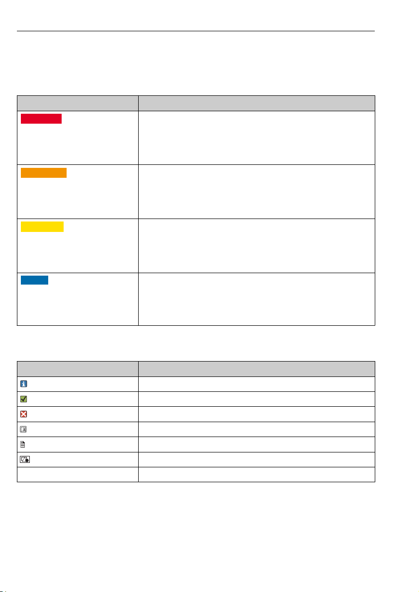
1.2 Symbols used ........................ 4
1.3 Symbols on the device ................ 5
2 Basic safety instructions ....... 5
2.1 Requirements for personnel ........... 5
2.2 Designated use ...................... 5
2.3 Workplace safety .................... 5
2.4 Operational safety ................... 6
2.5 Product safety ....................... 6
3 Product description ............. 7
3.1 Product design ....................... 7
4 Incoming acceptance and
product identification .......... 9
4.1 Incoming acceptance ................. 9
4.2 Product identification ................ 10
4.3 Scope of delivery .................... 10
4.4 Certificates and approvals ............ 11
5 Installation .................... 12
5.1 Installation conditions ............... 12
5.2 Mounting the assembly .............. 20
5.3 Post-installation check ............... 33
6 Commissioning ................ 34
6.1 Function check ..................... 34
7 Operation ...................... 35
7.1 Adapting the device to the process
conditions ......................... 35
8 Maintenance .................. 36
8.1 Maintenance tasks .................. 36
9 Repair .......................... 43
9.1 General notes ...................... 43
9.2 Spare parts ........................ 44
9.3 Return ............................ 46
9.4 Disposal .......................... 46
10 Accessories .................... 46
10.1 Device-specific accessories ............ 46
10.2 Service-specific accessories ........... 49
10.3 Accessory kits ...................... 49
11 Technical data ................. 50
11.1 Environment ....................... 50
11.2 Process ............................ 50
11.3 Mechanical construction ............. 50
Index ................................. 52

About this document Cleanfit COA451
4 Endress+Hauser
1 About this document
1.1 Warning sign
Structure of information Meaning
LDANGER
Causes (/consequences)
If necessary, Consequences of non-
compliance (if applicable)
‣Corrective action
This symbol alerts you to a dangerous situation.
Failure to avoid the dangerous situation will result in a fatal or serious injury.
LWARNING
Causes (/consequences)
If necessary, Consequences of non-
compliance (if applicable)
‣Corrective action
This symbol alerts you to a dangerous situation.
Failure to avoid the dangerous situation can result in a fatal or serious injury.
LCAUTION
Causes (/consequences)
If necessary, Consequences of non-
compliance (if applicable)
‣Corrective action
This symbol alerts you to a dangerous situation.
Failure to avoid this situation can result in minor or more serious injuries.
NOTICE
Cause/situation
If necessary, Consequences of non-
compliance (if applicable)
‣Action/note
This symbol alerts you to situations which may result in damage to property.
1.2 Symbols used
Symbol Meaning
Additional information, tips
Permitted or recommended
Not permitted or not recommended
Reference to device documentation
Reference to page
Reference to graphic
Result of a step

Cleanfit COA451 Basic safety instructions
Endress+Hauser 5
1.3 Symbols on the device
Symbol Meaning
Reference to device documentation
2 Basic safety instructions
2.1 Requirements for personnel
• Installation, commissioning, operation and maintenance of the measuring system may be
carried out only by specially trained technical personnel.
• The technical personnel must be authorized by the plant operator to carry out the specified
activities.
• The electrical connection may be performed only by an electrical technician.
• The technical personnel must have read and understood these Operating Instructions and
must follow the instructions contained therein.
• Faults at the measuring point may only be rectified by authorized and specially trained
personnel.
Repairs not described in the Operating Instructions provided must be carried out only
directly at the manufacturer's site or by the service organization.
2.2 Designated use
The manually operated Cleanfit COA451 retractable assembly is designed for the installation
of oxygen sensors in vessels and pipelines. Their mechanical construction means that they can
be operated in pressurized systems (see technical data).
The assembly is designed exclusively for use in liquid media.
Use of the device for any purpose other than that described, poses a threat to the safety of
people and of the entire measuring system and is therefore not permitted.
The manufacturer is not liable for damage caused by improper or non-designated use.
2.3 Workplace safety
As the user, you are responsible for complying with the following safety conditions:
• Installation guidelines
• Local standards and regulations
Electromagnetic compatibility
• The product has been tested for electromagnetic compatibility in accordance with the
applicable international standards for industrial applications.
• The electromagnetic compatibility indicated applies only to a product that has been
connected in accordance with these Operating Instructions.

Basic safety instructions Cleanfit COA451
6 Endress+Hauser
2.4 Operational safety
Before commissioning the entire measuring point:
1. Verify that all connections are correct.
2. Ensure that electrical cables and hose connections are undamaged.
3. Do not operate damaged products, and protect them against unintentional operation.
4. Label damaged products as defective.
During operation:
‣If faults cannot be rectified:
products must be taken out of service and protected against unintentional operation.
LCAUTION
Cleaning not switched off during calibration or maintenance activities
Risk of injury due to medium or cleaning agent!
‣If a cleaning system is connected, switch it off before removing a sensor from the medium.
‣If you wish to check the cleaning function and have therefore not switched off the cleaning
system, wear protective clothing, goggles and gloves or take other appropriate measures.
2.5 Product safety
2.5.1 State-of-the-art technology
The product is designed to meet state-of-the-art safety requirements, has been tested, and
left the factory in a condition in which it is safe to operate. The relevant regulations and
international standards have been observed.

Cleanfit COA451 Product description
Endress+Hauser 7
3 Product description
3.1 Product design
1
2
3
4
5
6
8
9
10
7
A0038438
1 Assembly in operational state (ball valve open)
1 Bracket for sensor holder
2 Sensor holder
3 Bayonet lock
4 Securing screws
5 Grease nipple
6 Ball valve/valve for venting or rinse connection
7 Process connection
8 Retraction pipe
9 Hand lever for opening/closing the ball valve
10 Handles
An additional rinse chamber valve can be mounted in the locking screw opposite the vent
valve.

Product description Cleanfit COA451
8 Endress+Hauser
3.1.1 Universal sensor holder
The sensor holder is used to position the sensor correctly in order to ensure correct measuring
accuracy.
If the sensor is not positioned correctly, the ball valve may be blocked or the sensor may be
located in the dead space as a result.
12
A0038451
2 Short sensor holder
1 Mounting position of the bayonet nut to hold the relevant sensor
2 Grooves of the safety rings to mount the bayonet nut

Cleanfit COA451 Incoming acceptance and product identification
Endress+Hauser 9
A0038479
3 Mounting position of the bayonet nut for CUS65D or COS51D
The name indicated on the holder serves as a mounting aid. The bayonet nut covers over
the marking for the selected sensor position.
4 Incoming acceptance and product identification
4.1 Incoming acceptance
1. Verify that the packaging is undamaged.
Notify the supplier of any damage to the packaging.
Keep the damaged packaging until the issue has been resolved.
2. Verify that the contents are undamaged.
Notify the supplier of any damage to the delivery contents.
Keep the damaged goods until the issue has been resolved.
3. Check that the delivery is complete and nothing is missing.
Compare the shipping documents with your order.
4. Pack the product for storage and transportation in such a way that it is protected
against impact and moisture.
The original packaging offers the best protection.
Make sure to comply with the permitted ambient conditions.
If you have any questions, please contact your supplier or your local Sales Center.

Incoming acceptance and product identification Cleanfit COA451
10 Endress+Hauser
4.2 Product identification
4.2.1 Nameplate
The nameplate provides you with the following information on your device:
• Manufacturer identification
• Order code
• Extended order code
• Operating conditions
• Serial number
• Safety information and warnings
• Approvals as per version ordered
‣Compare the information on the nameplate with the order.
4.2.2 Identifying the product
Product page
www.endress.com/COA451
Interpreting the order code
The order code and serial number of your product can be found in the following locations:
• On the nameplate
• In the delivery papers
Obtaining information on the product
1. Go to www.endress.com.
2. Call up the site search (magnifying glass).
3. Enter a valid serial number.
4. Search.
The product structure is displayed in a popup window.
5. Click on the product image in the popup window.
A new window (Device Viewer) opens. All of the information relating to your
device is displayed in this window as well as the product documentation.
4.2.3 Manufacturer's address
Endress+Hauser Conducta GmbH+Co. KG
Dieselstraße 24
D-70839 Gerlingen
4.3 Scope of delivery
The delivery comprises:
• Assembly in the version ordered
• Operating Instructions, English.

Cleanfit COA451 Incoming acceptance and product identification
Endress+Hauser 11
If you have any questions, please contact your supplier or your local sales center.
4.4 Certificates and approvals
4.4.1 CE/PED
The assembly has been manufactured according to good engineering practice as per Article 4,
Paragraph 3 of the Pressure Equipment Directive 2014/68/EU and is therefore not required
to bear the CE label.

Installation Cleanfit COA451
12 Endress+Hauser
5 Installation
5.1 Installation conditions
5.1.1 Dimensions
Assembly with G2" thread and weld-in adapter in measuring position (long and short
stroke)
226 (8.90)
Ø 49.3
(1.94)
X0
100
(3.94)
Ø 46
(1.81)
106
(4.17)
1 (0.04)
X1
311 (12.24)
67
(2.64)
185 (7.28)
270 (10.63)
109.5 (4.31)
92 (3.62)
115.5 (4.55)
Ø 86 (3.39)
Ø 91 (3.58)
X0
A0038481
4 Dimensions in mm (in)
X0,
X1
Dimensions depend on the sensor

Cleanfit COA451 Installation
Endress+Hauser 13
Assembly with G2" thread and weld-in adapter in service position (long and short
stroke)
101 (3.98)
X2
171
(6.73)
100
(3.94)
32
(1.26)
X2
276 (10.87)
A0038630
5 Dimensions in mm (in)
X2 Dimensions depend on the sensor

Installation Cleanfit COA451
14 Endress+Hauser
Assembly with flange connection
Ø 49.3
(1.94)
Ø 46
106 (4.17)
X0
100
(3.94)
X1
85
(3.35)
32 (1.26)
226 (8.90)
(1.81)
32
(1.26)
X2
276 (10.87)
100
(3.94)
101 (3.98)
A0038651
6 Dimensions in mm (in)
X0,
X2
Dimensions depend on the sensor
Sensor X0
CUS52D 25 (0.98)
CUS50D 26 (1)
CUS41/ 16 (0.63)
CUS51D 5 (0.2)
COS61D 12 (0.47)
CUS65 21 (0.83)
COS51D 12 (0.47)

Cleanfit COA451 Installation
Endress+Hauser 15
Sensor measuring
position
X1
CUS52D 139 (5.47)
CUS50D 110 (4.33)
CUS41/CUS51D, COS61D 101 (3.98)
CUS65, COS51D 59 (2.32)
Sensor service position,
long
X2
CUS52D 638 (25.12)
CUS50D 609 (23.98)
CUS41/CUS51D, COS61D 600 (23.62)
CUS65, COS51D 558 (21.97)
Sensor service position,
short
X2
CUS52D 533 (20.98)
CUS50D 504 (19.84)
CUS41/CUS51D, COS61D 495 (19.49)
CUS65, COS51D 453 (17.83)

Installation Cleanfit COA451
16 Endress+Hauser
Sensor holder with sensors
9.25
(0.37)
51.4
(2.02)
60.2
(2.37)
89.5
(3.52)
COS51D
CUS65(D)
COS61(D)
CUS41(D)
CUS51D
CUS50D
CUS52D
131
(5.16)
173 (6.81)
182 (7.17)
211 (8.31)
32
(1.26)
A0038478
7 Dimensions of sensor holder with sensors in mm (in)

Cleanfit COA451 Installation
Endress+Hauser 17
5.1.2 Process connections
A
2"
32 (1.26)
a
b
BC
A0038650
8 Dimensions of process connections in mm (in)
A G2" female thread
B G2" female thread with weld-in adapter
C Flange DN 50 / PN 16 (as per EN 1092-1) and flange ANSI 2" / 150 lbs
a DN 50: Ø 125 (4.92), ANSI 2": Ø 120.7 (4.75)
b DN 50: Ø 165 (6.50), ANSI 2": Ø 152.4 (6.00)

Installation Cleanfit COA451
18 Endress+Hauser
5.1.3 Installation instructions
Mounting location
The assembly is designed for installation on vessels and pipes. Suitable nozzles must be
available for this. The minimum pipe diameter is DN 80.
‣Before mounting the sensor, mount the assembly on the vessel or in the pipe.
The following diagram shows different installation positions in pipes, and indicates whether
they are permitted or not.
A0038661
9 Schematic of installation positions and orientations
‣Ideally, the assembly should be mounted in an ascending pipe. Installation in a horizontal
pipe is also possible.
• Install the sensor in places with uniform flow conditions.
• Do not install the sensor in places where air may collect or foam bubbles form or where
suspended particles may settle.
• Avoid installation in the down pipe.
• Avoid fittings downstream from pressure reduction stages which can lead to outgassing.

Cleanfit COA451 Installation
Endress+Hauser 19
Orientations
1
3
4
2
A0038660
10 Orientations, schematic
1 Sensor (see Accessories)
2 Transmitter
3 Retractable assembly
4 Direction of flow
The orientation depends on the sensor head. Pay attention to the Operating Instructions
for the relevant sensor. An inclination of at least 15° is recommended for amperometric
sensors
‣Make sure to avoid a siphon effect at the rinse chamber outlet. The inflow to the rinse
chamber is always from below.
a
190°
a
A0024141
11 Ascending pipe or vessel at side
α At least 15°
1 Flow direction
a a
A0024142
12 Vessel from above
α At least 15°, recommended 90°

Installation Cleanfit COA451
20 Endress+Hauser
5.2 Mounting the assembly
LWARNING
Medium flows out.
Risk of injury
‣Only install the assembly when the process is deactivated.
‣Before disassembling, always ensure that the process pipe and vessel are unpressurized,
empty and rinsed.
‣Move the assembly to the service position.
‣Close the ball valve.
5.2.1 Installing the assembly in the process
1. Mount the hand lever on the assembly.
2. Open the ball valve.
3. Move the assembly to the service position.
Retraction pipe is in the assembly.
4. Secure the assembly to the vessel or pipe using the selected process connection.
Flange process connection:
‣Prior to installation, check the flange seal between the flanges.
G2" process connection
‣Use a commercially available sealant (e.g. LOCTITE 561) to seal the G2" process connection.
5.2.2 Rinse water connection (optional)
NOTICE
Water pressure too high
The assembly can be damaged.
‣A pressure-reducing valve must be connected in series upstream if the water pressure can
increase to over 10 bar (87 psi).
Rinse the sensor in the service position with a second ball valve for the rinse chamber (see
accessories).
1. Connect the rinse water line to the rinsing nozzle provided. The two rinse nozzles on the
assembly are identical and can be used in the inlet and outlet.
2. Operate the rinse water connection of the assembly with a water pressure of 2 bar to
max. 6 bar (29 to 87 psi).
3. Also install a check valve and a dirt trap (100 μm, see "Accessories") in the water pipe (at
the inlet to the assembly).
Apart from water, you can also pass other or additional cleaning solutions through the
rinse chamber. When doing so, pay attention to the material resistance of the assembly
and make sure to comply with the maximum permitted temperatures and pressures.
Other manuals for Cleanfit COA451
1
Table of contents
Other Endress+Hauser Control Unit manuals

Endress+Hauser
Endress+Hauser Prosonic S FMU90 User manual

Endress+Hauser
Endress+Hauser CYA251 User manual

Endress+Hauser
Endress+Hauser Tank Side Monitor NRF590 User manual

Endress+Hauser
Endress+Hauser Nivotester FTR325 User manual

Endress+Hauser
Endress+Hauser VU340 User manual

Endress+Hauser
Endress+Hauser RNF22 User manual

Endress+Hauser
Endress+Hauser TMD1000 TMD1 User manual

Endress+Hauser
Endress+Hauser Tankvision NXA820 User manual

Endress+Hauser
Endress+Hauser Tankvision Multi Scan NXA83B User manual

Endress+Hauser
Endress+Hauser analytikjena TOC module User manual