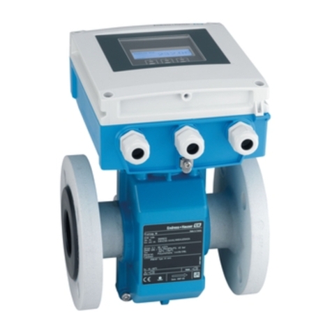
Promag 53 PROFIBUS-DP/-PA Contents
Endress+Hauser 3
Contents
1 Safety instructions . . . . . . . . . . . . . . 5
1.1 Designated use . . . . . . . . . . . . . . . . . . . . . . . . 5
1.2 Installation, commissioning and operation . . . 5
1.3 Operational safety . . . . . . . . . . . . . . . . . . . . . . 5
1.4 Return . . . . . . . . . . . . . . . . . . . . . . . . . . . . . . . 6
1.5 Notes on safety conventions and icons . . . . . . 6
2 Identification . . . . . . . . . . . . . . . . . . . 7
2.1 Device designation . . . . . . . . . . . . . . . . . . . . . 7
2.1.1 Nameplate of the transmitter . . . . . . . . 7
2.1.2 Nameplate of the sensor . . . . . . . . . . . . .8
2.2 CE mark, declaration of conformity . . . . . . . . . 8
2.3 Device certification PROFIBUS-DP/-PA . . . . . . 9
2.4 Registered trademarks . . . . . . . . . . . . . . . . . . 9
3 Installation. . . . . . . . . . . . . . . . . . . . 11
3.1 Incoming acceptance, transport and storage 11
3.1.1 Incoming acceptance . . . . . . . . . . . . 11
3.1.2 Transport . . . . . . . . . . . . . . . . . . . . . . 11
3.1.3 Storage . . . . . . . . . . . . . . . . . . . . . . . . 12
3.2 Installation conditions . . . . . . . . . . . . . . . . . . 13
3.2.1 Dimensions . . . . . . . . . . . . . . . . . . . . . 13
3.2.2 Mounting location . . . . . . . . . . . . . . . . 13
3.2.3 Orientation . . . . . . . . . . . . . . . . . . . . . . .15
3.2.4 Inlet and outlet runs. . . . . . . . . . . . . . . .16
3.2.5 Vibrations . . . . . . . . . . . . . . . . . . . . . . 16
3.2.6 Foundations, supports. . . . . . . . . . . . . .17
3.2.7 Adapters . . . . . . . . . . . . . . . . . . . . . . . .18
3.2.8 Nominal diameter and flow rate . . . . . 18
3.2.9 Length of connecting cable . . . . . . . . .24
3.3 Installation . . . . . . . . . . . . . . . . . . . . . . . . . . . 25
3.3.1 Installing the Promag W sensor . . . . . 25
3.3.2 Installing the Promag P sensor . . . . . . .31
3.3.3 Installing the Promag H sensor . . . . . . .37
3.3.4 Turning the transmitter housing. . . . . . .40
3.3.5 Installing the wall-mount transmitter
housing . . . . . . . . . . . . . . . . . . . . . . . . .41
3.3.6 Turning the local display . . . . . . . . . . . .43
3.4 Installation check . . . . . . . . . . . . . . . . . . . . . . 44
4 Wiring. . . . . . . . . . . . . . . . . . . . . . . . 45
4.1 Cable specifications for PROFIBUS-DP/-PA . 45
4.1.1 PROFIBUS-DP: Cable specifications . 45
4.1.2 PROFIBUS-PA: Cable specifications. . .48
4.2 Connecting the remote version . . . . . . . . . . . 50
4.2.1 Connecting Promag W / P / H . . . . . . 50
4.2.2 Cable specifications . . . . . . . . . . . . . . .52
4.3 Connecting the measuring unit . . . . . . . . . . . 53
4.3.1 Connecting the transmitter . . . . . . . . . 53
4.3.2 Terminal assignment . . . . . . . . . . . . . 55
4.3.3 Fieldbus connector . . . . . . . . . . . . . . . .56
4.4 Potential equalisation . . . . . . . . . . . . . . . . . . . 58
4.4.1 Standard case . . . . . . . . . . . . . . . . . . 58
4.4.2 Special cases . . . . . . . . . . . . . . . . . . . . 59
4.5 Degree of protection . . . . . . . . . . . . . . . . . . . . 61
4.6 Electrical connection check . . . . . . . . . . . . . . 62
5 Operation. . . . . . . . . . . . . . . . . . . . . . 63
5.1 Operation at a glance . . . . . . . . . . . . . . . . . . . 63
5.2 Operation via the local display . . . . . . . . . . . . 64
5.2.1 Display and operating elements . . . . . 64
5.2.2 Brief description of the function matrix. 67
5.2.3 Error messages . . . . . . . . . . . . . . . . . . 69
5.3 Communications: PROFIBUS-DP/-PA . . . . . . . 70
5.3.1 PROFIBUS-DP/-PA technology . . . . . . 70
5.3.2 PROFIBUS-DP system architecture . . . 71
5.3.3 PROFIBUS-PA system architecture . . . 72
5.3.4 Acyclic data exchange. . . . . . . . . . . . . 74
5.4 Operation with the PROFIBUS configuration
programs . . . . . . . . . . . . . . . . . . . . . . . . . . . . 75
5.4.1 FieldTool™ operating program . . . . . . 75
5.4.2 Commuwin II operating program . . . . . 75
5.5 Hardware configuration . . . . . . . . . . . . . . . . . 83
5.5.1 Configuration of write protection . . . . . 83
5.5.2 Configuration of the device address . . 84
6 Commissioning. . . . . . . . . . . . . . . . . 85
6.1 Function check . . . . . . . . . . . . . . . . . . . . . . . . 85
6.2 Commissioning the PROFIBUS-DP/-PA
interface using the local display . . . . . . . . . . . 86
6.3 Commissioning using the Class 2 master
(Commuwin II) . . . . . . . . . . . . . . . . . . . . . . . . . 87
6.3.1 Rescaling the input value . . . . . . . . . . . 89
6.4 System integration . . . . . . . . . . . . . . . . . . . . . 90
6.4.1 Cyclic data exchange. . . . . . . . . . . . . . 93
6.4.2 Configuration examples with
Simatic S7 HW-Konfig . . . . . . . . . . . . . 99
6.4.3 Cycle times. . . . . . . . . . . . . . . . . . . . . 104
6.5 Empty-pipe/full-pipe calibration . . . . . . . . . . 106
6.6 Data storage device (DAT, F-Chip™) . . . . . . 107
7 Maintenance . . . . . . . . . . . . . . . . . . 109
8 Accessories . . . . . . . . . . . . . . . . . . . 111
9 Trouble-shooting . . . . . . . . . . . . . . 113
9.1 Trouble-shooting instructions . . . . . . . . . . . . 113
9.2 System and process error messages . . . . . . 115
9.3 Process errors without messages . . . . . . . . . 121
9.4 Spare parts . . . . . . . . . . . . . . . . . . . . . . . . . . 122
9.5 Removing and installing printed circuit
boards . . . . . . . . . . . . . . . . . . . . . . . . . . . . . . 123
9.6 Replacing the device fuse . . . . . . . . . . . . . . 127
9.7 Replacing exchangeable measuring
electrodes . . . . . . . . . . . . . . . . . . . . . . . . . . . 128
