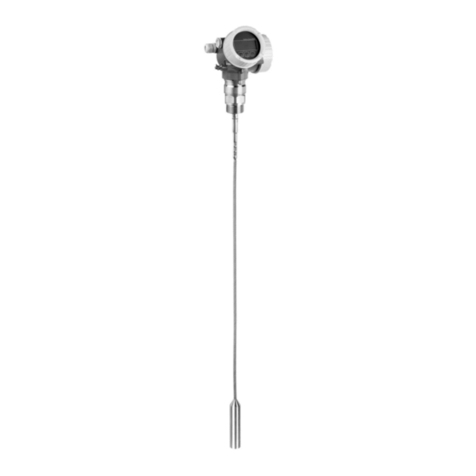
Proserve NMS80 Table of contents
Endress+Hauser 3
Table of contents
1 Declaration of conformity ........... 4
1.1 Other safety-related characteristic values ..... 6
1.2 Useful lifetime of electrical components ...... 6
2 Document information .............. 7
2.1 Document function ..................... 7
2.2 Using this document .................... 7
2.2.1 Information on the document
structure ....................... 7
2.3 Symbols used .......................... 7
2.3.1 Safety symbols .................. 7
2.3.2 Symbols for
certain types of information ......... 7
2.3.3 Symbols in graphics ............... 8
2.4 Supplementary device documentation ........ 8
3 Permitted devices types ............. 9
3.1 SIL label on the nameplate ............... 10
4 Safety function .................... 10
4.1 Definition of the safety function ........... 10
4.2 Safety-related signal ................... 10
4.3 Restrictions for use in safety-related
applications ......................... 11
4.3.1 Dangerous undetected failures in this
scenario ...................... 12
5 Use in safety instrumented
systems ........................... 13
5.1 Device behavior during operation .......... 13
5.1.1 Device behavior when switched on ... 13
5.1.2 Device behavior when safety
function is requested ............. 13
5.1.3 Device behavior in the event of
alarms and warnings ............. 13
5.1.4 Alarm and warning messages ...... 13
5.1.5 Device behavior when switched on ... 13
5.1.6 Device behavior when safety
function is requested ............. 13
5.1.7 Device behavior in the event of
alarms and warnings ............. 14
5.1.8 Alarm and warning messages ...... 14
5.2 Device configuration for safety-related
applications .......................... 14
5.2.1 Calibration of the measuring point -
safety function 1 (level
measurement) ................. 14
5.2.2 Calibration of the measuring point -
safety function 2 (current input
measurement) ................. 15
5.2.3 Configuration method ........... 16
5.3 Proof testing ......................... 21
5.3.1 Test sequence A (Approach the
level) ........................ 22
5.3.2 Test sequence B (simulate the level) .. 24
5.3.3 Test sequence C (simulation and
single-point level detection) ........ 26
5.3.4 Test sequence D (Feed in real
currents) ...................... 29
6 Life cycle ......................... 31
6.1 Requirements for personnel .............. 31
6.2 Installation .......................... 31
6.3 Commissioning ....................... 31
6.4 Operation ........................... 31
6.5 Maintenance ......................... 31
6.6 Repairs ............................. 32
6.7 Modification ......................... 33
7 Appendix ......................... 34
7.1 Structure of the measuring system ......... 34
7.1.1 System components ............. 34
7.1.2 Description of use as a protective
system ....................... 34
7.2 Proof testing ......................... 36
7.3 Notes on the redundant configuration of
multiple sensors ...................... 36
7.4 Further information .................... 37
