manuals.online logo
Brands
  1. Home
  2. •
  3. Brands
  4. •
  5. Endress+Hauser
  6. •
  7. Measuring Instrument
  8. •
  9. Endress+Hauser Stamosens CXM750 Technical specifications

Endress+Hauser Stamosens CXM750 Technical specifications

This manual suits for next models

1

Other Endress+Hauser Measuring Instrument manuals

Endress+Hauser Soliwave FQR56 User manual

Endress+Hauser

Endress+Hauser Soliwave FQR56 User manual

Endress+Hauser ria45 Technical specifications

Endress+Hauser

Endress+Hauser ria45 Technical specifications

Endress+Hauser Cerabar S PMP71 Instructions for use

Endress+Hauser

Endress+Hauser Cerabar S PMP71 Instructions for use

Endress+Hauser Nivocompact FTC 131 Manual

Endress+Hauser

Endress+Hauser Nivocompact FTC 131 Manual

Endress+Hauser Proline t-mass T 150 Technical specifications

Endress+Hauser

Endress+Hauser Proline t-mass T 150 Technical specifications

Endress+Hauser Proline Promag H 500 User manual

Endress+Hauser

Endress+Hauser Proline Promag H 500 User manual

Endress+Hauser Proline Promag W 400 Technical specifications

Endress+Hauser

Endress+Hauser Proline Promag W 400 Technical specifications

Endress+Hauser Memobase Plus CYZ71D User manual

Endress+Hauser

Endress+Hauser Memobase Plus CYZ71D User manual

Endress+Hauser Liquiphant M FTL50 Manual

Endress+Hauser

Endress+Hauser Liquiphant M FTL50 Manual

Endress+Hauser Cerabar M PMP55 User manual

Endress+Hauser

Endress+Hauser Cerabar M PMP55 User manual

Endress+Hauser Liquiline CA80SI Technical specifications

Endress+Hauser

Endress+Hauser Liquiline CA80SI Technical specifications

Endress+Hauser FMU 40 Parts list manual

Endress+Hauser

Endress+Hauser FMU 40 Parts list manual

Endress+Hauser RIA14 User manual

Endress+Hauser

Endress+Hauser RIA14 User manual

Endress+Hauser Liquitrend QMW43 User manual

Endress+Hauser

Endress+Hauser Liquitrend QMW43 User manual

Endress+Hauser FQG60 Manual

Endress+Hauser

Endress+Hauser FQG60 Manual

Endress+Hauser HART Proline Promag 51 User manual

Endress+Hauser

Endress+Hauser HART Proline Promag 51 User manual

Endress+Hauser Soliwave FQR56 User manual

Endress+Hauser

Endress+Hauser Soliwave FQR56 User manual

Endress+Hauser Proline Promass 83 User manual

Endress+Hauser

Endress+Hauser Proline Promass 83 User manual

Endress+Hauser Dosimag User manual

Endress+Hauser

Endress+Hauser Dosimag User manual

Endress+Hauser Liquiphant M FTL51C User manual

Endress+Hauser

Endress+Hauser Liquiphant M FTL51C User manual

Endress+Hauser Levelflex M FMP45 User manual

Endress+Hauser

Endress+Hauser Levelflex M FMP45 User manual

Endress+Hauser Proline Promass 83 Technical specifications

Endress+Hauser

Endress+Hauser Proline Promass 83 Technical specifications

Endress+Hauser CE 4 User manual

Endress+Hauser

Endress+Hauser CE 4 User manual

Endress+Hauser Proline Promass 83 User manual

Endress+Hauser

Endress+Hauser Proline Promass 83 User manual

Popular Measuring Instrument manuals by other brands

Powerfix Profi 278296 Operation and safety notes

Powerfix Profi

Powerfix Profi 278296 Operation and safety notes

Test Equipment Depot GVT-427B user manual

Test Equipment Depot

Test Equipment Depot GVT-427B user manual

Fieldpiece ACH Operator's manual

Fieldpiece

Fieldpiece ACH Operator's manual

FLYSURFER VIRON3 user manual

FLYSURFER

FLYSURFER VIRON3 user manual

GMW TG uni 1 operating manual

GMW

GMW TG uni 1 operating manual

Downeaster Wind & Weather Medallion Series instruction manual

Downeaster

Downeaster Wind & Weather Medallion Series instruction manual

Hanna Instruments HI96725C instruction manual

Hanna Instruments

Hanna Instruments HI96725C instruction manual

Nokeval KMR260 quick guide

Nokeval

Nokeval KMR260 quick guide

HOKUYO AUTOMATIC UBG-05LN instruction manual

HOKUYO AUTOMATIC

HOKUYO AUTOMATIC UBG-05LN instruction manual

Fluke 96000 Series Operator's manual

Fluke

Fluke 96000 Series Operator's manual

Test Products International SP565 user manual

Test Products International

Test Products International SP565 user manual

General Sleep Zmachine Insight+ DT-200 Service manual

General Sleep

General Sleep Zmachine Insight+ DT-200 Service manual

Sensa Core Lacto Spark user manual

Sensa Core

Sensa Core Lacto Spark user manual

VOLTCRAFT UTS-1980 operating instructions

VOLTCRAFT

VOLTCRAFT UTS-1980 operating instructions

EBCHQ 94915 Operation manual

EBCHQ

EBCHQ 94915 Operation manual

Balluff BIP LD2-T017-01-EP-S4 Series user guide

Balluff

Balluff BIP LD2-T017-01-EP-S4 Series user guide

Pulsar IMP Lite Series instruction manual

Pulsar

Pulsar IMP Lite Series instruction manual

ETCR 6800 user manual

ETCR

ETCR 6800 user manual

manuals.online logo
manuals.online logoBrands
  • About & Mission
  • Contact us
  • Privacy Policy
  • Terms and Conditions

Copyright 2025 Manuals.Online. All Rights Reserved.

KA215C/07/en/07.04
Brief Operating Instructions
Stamosens CXM750/CXS70
Warning!
These Brief Operating Instructions do not substitute the Operating Instructions!
In particular pay attention to the safety instructions in chapter 1 and to the special notes in the other chapters of the Operating Instructions!
#
Installation and Wiring
Installation
• Select a measuring point where representative measurement can be taken.
Do not mount the sensor where medium flow is turbulent and fast-flowing.
• We recommend to fit the transmitter with a weather protection cover (see
"Accessories").
• Attach the sensor to a special extension tube. Due to the weight of the sensor
(approx. 5 kg), the sensor cable does not provide sufficient support. Never carry the
sensor by its cable.
• The best fixture is a pendulum frame which holds the sensor vibration-free.
• Install the system at an easily accessible position to prevent danger for the operating
personnel (during commissioning or when carrying out maintenance and cleaning
work).
• Route all cable connections to prevent mechanical damage and interference from
other lines.
• Install measuring channels of the sensor in the direction of flow to obtain a self-
cleaning effect.
• The activated sludge version of the sensor is equipped with a cleaning unit which
prevents soiling or blocking due to particles by compressed air. For other applications
with soiling contents, the cleaning unit is available as an accessory.
Install the air outflow of the cleaning unit at the narrow side of the light slit.
a0000949-en
Abb. 1: Transmitter dimensions
a0000950-en
Abb. 2: Sensor dimensions
241/9.49
198/7.80
329 / 12.95 185 / 7.28
60 / 2.36
60/2.36
69/2.72
26 / 1.02
145 / 5.79
15 / 0.59
212/8.35
198 / 7.80
145 / 5.71
15 / 0.59
115/4.53
mm / inch
Ø127/5.0
G1½
360 / 14.17
mm / inch
Electrical connection
Terminal assignment
a0000952
Fig. 3: Electrical connection transmitter with power supply 80 ... 250 V AC
a0000953
Fig. 4: Electrical connection transmitter with power supply 24 V AC/DC
Cleaning unit
a0000951-en
Fig. 5: Connection of the cleaning unit
Relais: Load/Last max. 250V~/2A, 30V=/1A
Supply / Netz:
80-250 V~
L
14101619
Shield/
Schirm
NO
NC
COM
713
Alarm 1/
GW 1
Hold
Error/
Störung
Cleaning/
Reinigung
Input /
Eingang
Output /
Ausgang
RS232 Alarm 2/
GW 2
N25111720 GND
22 RxD
814
36121821 CTS
23 TxD
915
T 500 mA
F1
Klemmen führen auch bei ausgeschaltetem Gerät Spannung !!!
51509157 Terminals voltage to ground even when the unit is switched off !!!
Sensor 1
+
-
24
2831
I1
I2
24V DC / 100mA
25
2932
27
+24V
+24V
26
0V
0V
3033
0/4-20 mA
Shield/
Schirm
Duo-
Version:
Sensor 2
+
-
Relais: Load/Last max. 250V~/2A, 30V=/1A
14101619
Shield/
Schirm
NO
NC
COM
713
Alarm 1/
GW 1
Hold
Error/
Störung
Cleaning/
Reinigung
Input /
Eingang
Output /
Ausgang
RS232 Alarm 2/
GW 2
25111720 GND
22 RxD
814
36121821 CTS
23 TxD
915 F1
51509391
Sensor 1
+
-
24
2831
I1
I2
24V DC / 100mA
25
2932
27
+24V
+24V
26
0V
0V
3033
0/4-20 mA
Shield/
Schirm
Duo-
Version:
Sensor 2
+
-
Supply voltage only 24V DC/AC !!!
Versorgungsspannung nur 24V DC/AC !!!
T2A
L
L
+
-
PE L1 N PE
T
1A
Transmitter
1
230V AC / 50Hz
115V AC / 60Hz
L
1
16
N2
3
18
Fuse
or
Commissioning
Operating keys and their function
The operating keys and the integrated indicator LEDs have the following functions:
First commissioning
!Note!
• Before switching the system on for the first time, familiarise yourself with the
operation of the transmitter. For this, see in particular chapters "Safety instructions"
and "Operation".
• The sensor should be left in the medium for approx. 1 hour, so that the sensor can
adapt to the medium temperature.
• The transmitter has already been pre-configured at the factory and starts measuring
automatically when switched on. Due to the different waste water composition, the
media can vary greatly. Therefore, we recommend using an application-specific
calibration for commissioning.
Key Key function Indicator LED function
H– “Auto measuring” option
– back to the main menu from all sub-menus
Alarm value 1 exceeded
K– backwards in the sub-menu
(horizontal, see Appendix,)
Alarm value 2 exceeded
V– backwards in the main menu (vertical)
–increasevalue
Measuring range exceeded
W– forwards in the main menu (vertical)
– reduce value
Measuring range undershot
F– select option
– adopt value, forwards in the sub-menu (horizontal)
Retrieve error message
J– selection in the sub-menu Unassigned
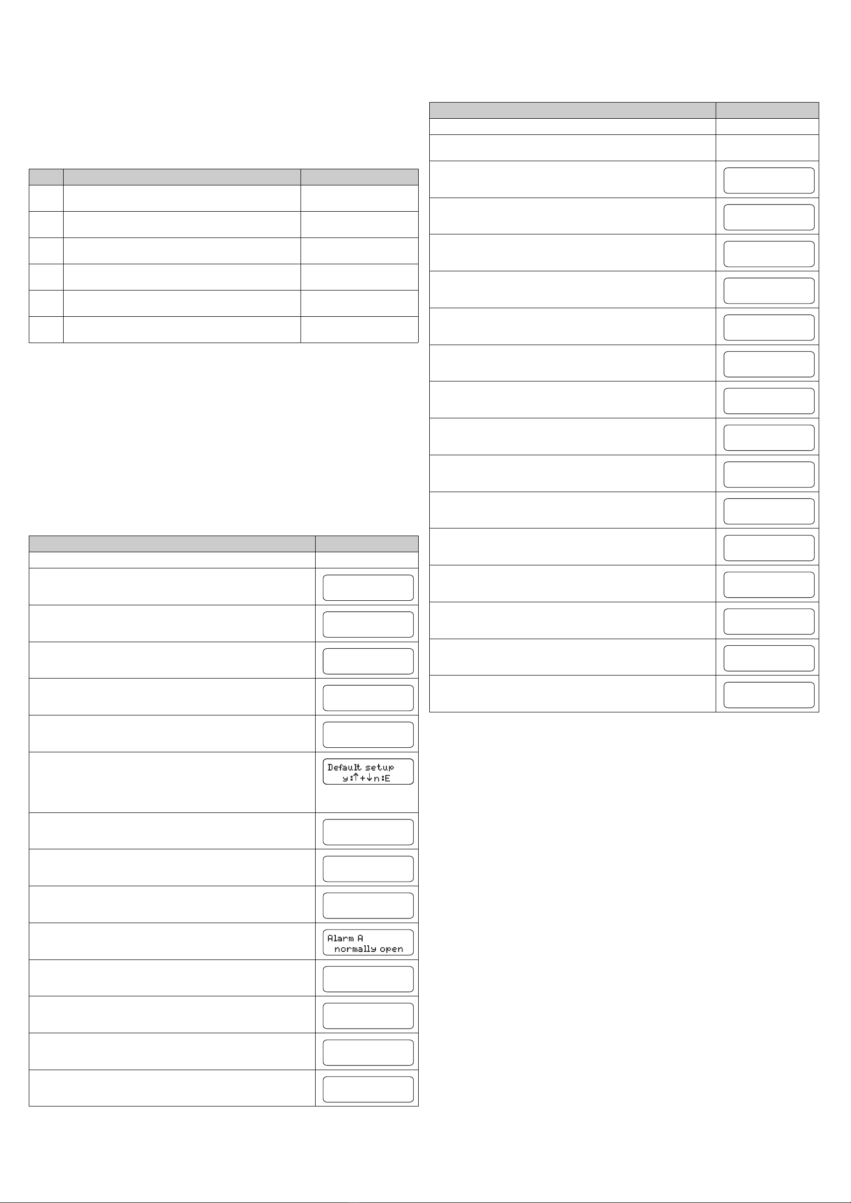
Action Display
Switch the transmitter on.
Press H.
Press five times Wand once F.
Press the Wkey to set the "99" code and confirm with F.
Use the Wor Vkeys to select your sensor and confirm with F.
Use the Wor Vkeys to select the desired unit of measure and confirm with F.
Hold down the Wand Vkeys simultaneously to activate the default setup for the
selected sensor type.
!Note!
The default setup is compulsory for initial start-up, in order to use the correct default
calibration.
Confirm the "Correction factor 0%" function with F.
Use the Wor Vkeys to select the number of measured values for forming the mean
value and confirm with F.
Use the Wor Vkeys to select the the current output and confirm with F.
Use the Wor Vkeys to select the configuration for alarm value A and confirm with
F.
Repeat the previous step for alarm value B.
Select the configuration for the diagnostic alarms similar to the alarm value setting.
Use the V, Wand Fkeys to set the current date and time. Confirm with F.
Press H. The system is ready for measurement now.
MEASUREMENT
CONFIGURATION
Code No.
99
NOx BS 0-30
Type of sensor
mg/l-N
Unit of measure
0%
Correct. factor
10
n mean value
4-20 mA
Analog output
Alarm B
normally open
Diagnostic alarm
normally open
10.02.02. 11:38
act. Date/Time
MEASUREMENT
One-point calibration
Three-point calibration
A one-point calibration is not useful for the activated sludge sensor. Therefore, carry
out a three-point calibration:
1. Take three samples at three times of different nitrate concentration and note down
the displayed frequency at the time of sampling.
!Note!
The concentrations must differ by 1 mg/l at minimum.
2. Determine the nitrate content of the samples in the laboratory.
3. Enter the value pairs of determined concentrations and noted frequencies (in order
of increasing resp. decreasing concentrations):
a. Proceed as with the one-point calibration (see above).
However, enter "3" instead of "1" for the number of measuring points in the
CALIBRATION POINTS menu .
b. Enter the first concentration in the NITRATE INPUT menu.
c. Enter the frequency value corresponding to the first concentration in the
FREQUENCY menu.
d. Repeat steps b and c for the remaining concentrations. After entering the last
frequency, return to the measuring mode.
The calibration is then finished.
Action Display
Leave the sensor to rest in the medium for approx. 1 hour.
Take a sample in the direct vicinity of the sensor and determine the nitrate content in the
laboratory.
Press H.
Press three times Fto display the sensor frequency associated with the measured value.
Note the sensor frequency value.
Press H.
Press twice Wand confirm with F.
Press the Wkey to set the "99" code and confirm with F.
Use the Wkey to set the number of measuring points to "1". Confirm with F.
Press H.
Press three times Wand confirm with F.
Press the Wkey to set the "99" code and confirm with F.
Use Wor Vto set the 1st measured value to the laboratory value. Confirm with F.
Press H.
Press four times Wand confirm with F.
Press the Wkey to set the "99" code and confirm with F.
Press three times Fto set the previously noted sensor frequency value.
Press H. The one-point calibration is now completed.
MEASUREMENT
Frequency
4836 Hz
MEASUREMENT
CALIBRATION PTS
Code No.
99
1
No. of points
MEASUREMENT
NITRATE INPUT
Code No.
99
1. Value
5.00 mg/l-N
MEASUREMENT
FREQUENCY
Code No.
99
Frequency
4836 Hz
MEASUREMENT