EnerSys Alpha XRT-TPPL User manual
1031-00014-B1-001, Rev. A (02/2023)
Introduction
The Alpha®Extended Runtime Thin Plate Pure Lead (XRT-TPPL) power system offers extended runtime for XM3.1-HP™
cable TV powering applications and solutions based on power supply loading that can be supported using two, four or
six battery string configurations. This guide briefly describes the XM3.1-HP power supply and provides procedures with
regard to the installation of the power supply, battery connection and initial start-up. The XM3.1-HP power supply requires
specific firmware to operate this system. For detailed information, refer to the Extended Runtime Thin Plate Pure Lead
(XRT-TPPL) Power System Technical Manual (Alpha p/n 031-00014-B0-001) available at www.alpha.com.
Audience
This guide is intended for experienced, qualified and licensed installation personnel familiar with the mechanical and
electrical requirements of enclosure and power supply systems. Review the support documentation on the website to
become familiar with the features and functions of the equipment in this system before proceeding.
1.0 Overview
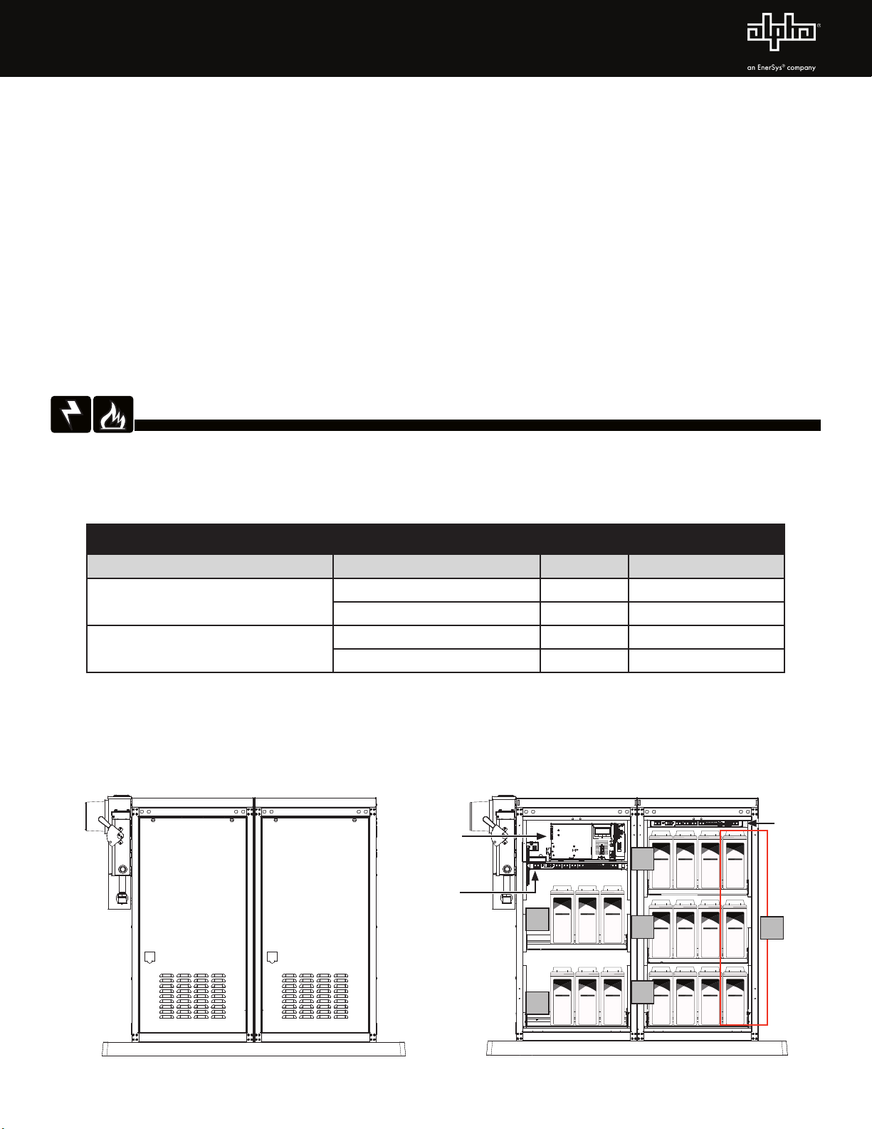
Battery string locations for an 18-battery configuration are noted in the image below as well as in Fig. 2-9 and Fig. 2-10.
Each string uses three batteries. Note that String D consists of the fourth battery on each row in the PN-4 FTB.
Extended Runtime Thin Plate Pure Lead (XRT-TPPL) Power System
Quick Start Guide
Fig. 1-1, PN-4 FT and PN-4 FTB XRT System
XM3.1
BROADBAND UPS
]
]
]
OUTPUT1
OUTPUT2
N+ 1
N
N
N
~
~
~
IntelligentInverter Module-IM3.1TM
BATTERY
TEMP
TORQUE
10.0 IN-LB
11.5kgf.cm
LRI
OUTPUT
ALARM
TEST
DS
OL
US
SFP
LNK
ALM/
RDY
E
T
H
GRN=OK
BLU=WARN
RED
=OUT
RST
RX/TX
PWR
TPR
A
STRGB
STRGC
STRGD
SMART
ALPHA
GUARD
E
N
V
BATTERYINPUT
BATTERY
BREAKER
RF
ACTIVE
PWR
COM
+
_
BIU
PN-4 FT PN-4 FT
PN-4 FTB PN-4 FTB
(Doors Removed)
XM3.1-HP XRT
BIU2
BIU1
AA
BB
C
WARNING! ELECTRICAL & FIRE HAZARD
• Failure to install and/or use this equipment as instructed in the system documents
can result in a hazard to personnel or damage to the equipment. This system is only
serviceable by qualified personnel.
• Maximum site load must not exceed the values in the table below:
Battery Configurations
Number of PN-4 Battery Enclosures Battery Type Quantity P/S Output Current
1 or 2 PowerSafe®SBS 190F TPPL 12 1 - 3 A
AlphaCell®210FTX TPPL 12 3.1 - 4 A
2PowerSafe® SBS 190F TPPL 18 4.1 - 5 A
AlphaCell®210FTX TPPL 18 5.1 - 6 A
D
2031-00014-B1-001, Rev. A (02/2023)
Procedure
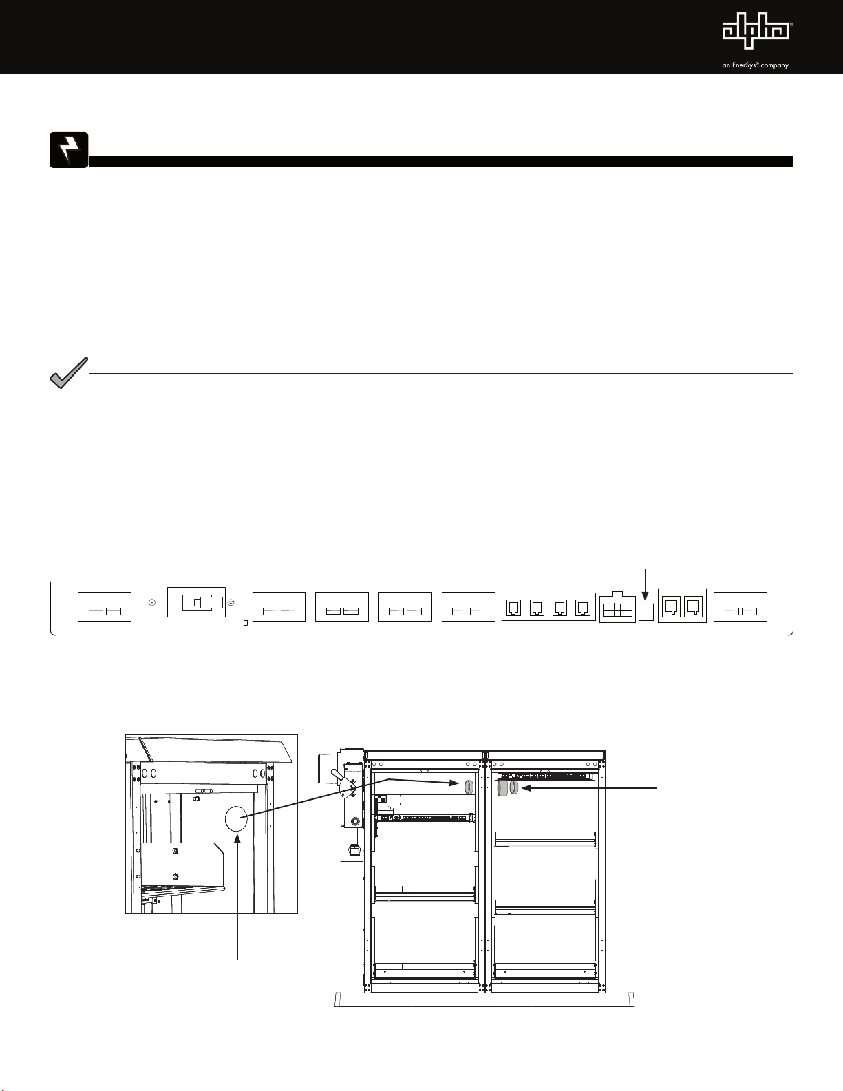
1. Before installing the batteries, ensure the enclosure(s) are set and bolted to pad. Remove bottom battery tray if
necessary.
2. Ensure enclosure grounding is in place.
3. Ensure BIU (Battery Interface Unit) is installed (see Fig. 1-1 for mounting locations) and verify the tamper switch (TPR)
is plugged in.
Fig. 2-2, Conduit PassThrough
Fig. 2-1, BIU Tamper Switch Location
2" Knockout
(Located on both enclosures)
Connect enclosures with
conduit pass through
2.0 Battery Installation And Start-Up Procedure
Required Tools
• Insulated tools (size and setting based on battery manufacturer torque specification)
• Safety glasses or face shield
• Rubber gloves
• Chest shield
• Box or bag for storing cables and hardware while out in the field
• True RMS voltmeter
Installer must wear the correct PPE when installing batteries. Failure to do so may result in
injury or death.
WARNING! ELECTRICAL HAZARD
Review Fig. 2-9 and Fig. 2-10 for hardware stack-up and wiring diagram to see the
recommended layout and set up, then proceed with the installation procedure below.
NOTICE:
4. Install conduit pass-through if side by side PN-4 enclosures are used. Use 2" conduit knockout on the side top front of
enclosure.
STRING B
STRING A
STRING C STRING D
PTS A
BATTERY TEMP SENSE
PTS B PTS C PTS D
80A CB
DC OUTPUT
BAT SNS
TPR COM 1 COM 2
DC INPUT
+
-+
-+
-+
-+
-+
-
PWR
A DCB
Tamper Switch (TPR)
3031-00014-B1-001, Rev. A (02/2023)
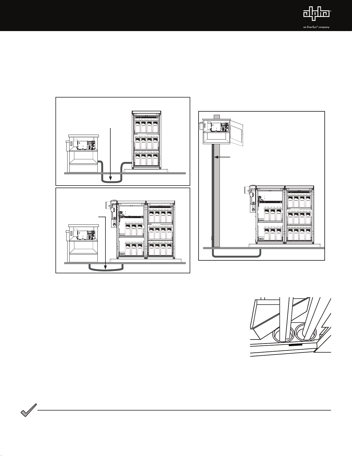
5. If integrating an existing ground mounted UPE or PWE cabinet, install metallic conduit run from the PN-4 FT to
existing enclosure (see figure below). Remove PN-4 bottom battery tray if necessary. Use 2" conduit knockout on
front side bottom of PN-4 or 2" knockout in bottom under battery tray to go under the pad. (Metallic conduit must be
used above ground to prevent radiated emissions. Metallic conduit must be ground bonded.)
6. If integrating a pole mounted enclosure, remove existing PWE batteries and slide trays so conduit can enter the
bottom of the enclosure. BIU Integration wires should be long enough to route to XM3.1-HP™ power supply battery
and RS485 COM connectors. Excess wire can be looped in the bottom of the PWE.
When installing PowerSafe®SBS 190F batteries, leave approximately 1½" of space behind the
batteries on the shelf. Always install batteries with the rear door removed to avoid slamming the
batteries into the rear door and causing damage.
NOTICE:
Fig. 2-3, Routing Conduit Underground Examples
Existing underground enclosure
5.5 Amp Draw
Add 1/2 or 2-inch metallic conduit
for battery cables and comms cable
PWR
COM
+
_
Existing underground enclosure
2 Amp Draw
Add 1 1/2 or 2-inch metallic conduit
for battery cables and comms cable
PWR
COM
+
_
Existing underground enclosure
5.5 Amp Draw
Add 1 1/2 or 2-inch metallic conduit
for battery cables and comms cable
PWR
COM
+
_
Existing Aerial Enclosure
5.5 Amp Draw
Existing Underground Enclosure
2 Amp Draw
Existing Underground Enclosure
5.5 Amp Draw
Add 1 ½" or 2" metallic conduit for
battery cables and COM cables
Add 1 ½" or 2"
metallic conduit for
battery cables and
COM cables
Add 1 ½" or 2" metallic
conduit for battery cables and
COM cables
Fig. 2-4, PN-4 FT Conduit Location
(Back of Enclosure)
7. Install grouped BIU extension, #6 AWG battery and COM cables in conduit run.
Remove 75A Anderson™ connector housing on the end to be pulled through
the conduit. Use appropriate wire pulling grip techniques to protect Anderson
terminals and RS485 COM connector. When in place, BIU extension wires must
be long enough to route from XM3.1-HP power supply to BIU1 connectors after
batteries are installed. Re-install 75A Anderson connector housing on battery
cables.
8. Ensure all PN-4 battery trays are installed correctly.
9. Verify XM3.1-HP power supply battery breaker and BIU circuit breakers are off.
10. With battery covers on, place batteries on shelves using proper lifting procedure.
This is a two-person operation. When installing AlphaCell®210FTX batteries leave
the rear handle flipped forward to aid in future removal. Use approximately ½"
spacing between batteries. On PN-4 FTB leave more space (approximately ¾")
between last battery in the first three string and the D string battery. This will
help with wiring the D string batteries.
4031-00014-B1-001, Rev. A (02/2023)
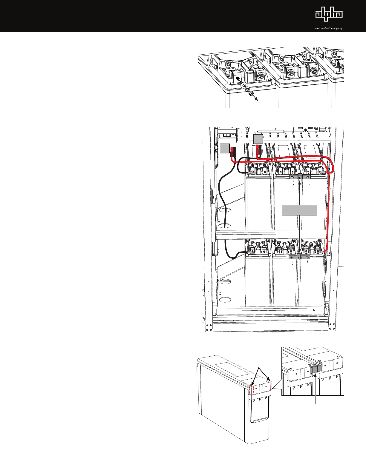
11. Remove all battery covers.
12. Remove all hardware from battery terminals and store in
a bag or convenient place. (Fig. 2-5)
13. Install 876-00059-20 BAT,INTG,36VDC,2STRG,PN4FT,W/
BIU,PTS,BS in the PN-4 FT with two battery trays. (See
Fig. 1-1, Fig. 2-9 and p/n 031-00014-08 System Wire
Diagram available on Alpha's website for reference.)
A. Start with A string battery cables on the bottom
tray of the PN-4 FT. Route the black wire through
the hole in left side of the top tray as seen in Fig.
2-6. Route the red wire along the right side of the
enclosure.
B. Install B string battery cables on middle tray.
C. Install intercell fuses on batteries 2A and 3A, and 2B
and 3B. (On AlphaCell® 210FTX batteries, the fuse
can be offset to the back. On PowerSafe® SBS 190F
batteries, the fuse must be offset to the front.)
D. Install interconnect bus bars on batteries 1A and 2A,
and 1B and 2B.
E. Install Precision Temperature Sensors (PTS). Plug in
to appropriate BIU1 port (ex: PTS A cable into the
PTS A BIU1 port) in turn so they don’t get mixed up.
Route wires down the right side. Use wire label A
& B provided by installer to mark both ends of PTS.
Note: The PTS are 4ft long.
F. Install battery voltage sense wires. Route wires
down the right side.
G. Torque battery terminals to battery manufacturer's
specifications.
H. Check battery cable connectors for correct polarity
and voltage. Verify connector color, orientation and
wire labels, then fully insert into BIU1.
Note: The BIU will power up as soon as the
batteries are connected, regardless of circuit
breaker position.
I. Before installing covers, use a corrosion inhibitor
such as NO-OX®electrical contact grease on battery
terminals. Install battery covers. (On PowerSafe SBS
190F batteries, the covers must be trimmed with
side cutters to fit around the intercell fuses. See Fig.
2-7. Trim side needed.)
14. Plug in battery voltage sense connector into BIU1.
15. Connect BIU1 extension cable from BIU DC Output to
XM3.1-HP™ power supply Battery Input.
16. Connect RS485 COM cable from BIU1 COM1 to
XM3.1-HP power supply BIU connection.
Fig. 2-5, Remove Battery Hardware
Fig. 2-6, Installing Battery Cables and Intercell Fuses
Fig. 2-7,Trimming Battery Cover on PowerSafe®SBS 190F
A
B
Intercell Fuses
1A
1B
2A
2B
3A
3B
Intercell Fuse
Trim the
side needed

5031-00014-B1-001, Rev. A (02/2023)
OUTPUT
ALARM
TEST
Fig. 2-8, XM3.1-HP™ Power Supply
Smart Display
1 7. Install 876-00059-22 BAT,INTG,36VDC,4STRG,PN4FT,W/BIU,PTS,BS in PN-4 FTB with 3 battery trays. (See Fig. 1-1,
Fig. 2-10 and p/n 031-00014-08 System Wire Diagram available on Alpha's website for reference.)
A. Start with A string battery cables on the bottom tray.
B. Install B string battery cables on middle tray.
C. Install C string battery cables on top tray.
D. Install D string battery cables.
E. Install intercell fuses on batteries 2A and 3A, 2B and 3B, and 2C and 3C. (On AlphaCell® 210FTX batteries the
fuse can offset to the back. On Powersafe®SBS 190F batteries the fuse must offset to the front.) If installing D
string batteries, use the F4 fuse wire kit between batteries 2D and 3D.
F. Install interconnect bus bars on batteries 1A and 2A, 1B and 2B and 1C and 2C. If installing D string batteries,
install an intercell jumper between batteries 1D and 2D.
G. Install Precision Temperature Sensors (PTS). Plug in to appropriate BIU2 port (ex: PTS A cable into the PTS A BIU2
port) in turn so they don’t get mixed up. Route wires down the right side. Use wire label A, B, C & D provided by
installer to mark both ends of PTS. Note: PTS A is 12ft. The rest are 4ft.
H. Install battery voltage sense wires. Route wires down the right side.
I. Torque battery terminals to battery manufacturer's specifications.
J. Check battery cable connectors for correct polarity and voltage. Verify connector color, orientation and wire labels
then fully insert into BIU2.
K. Before installing covers, use a corrosion inhibitor such as NO-OX®electrical contact grease on battery terminals.
Install battery covers. (On PowerSafe SBS 190F batteries the covers must be trimmed with side cutters to fit
around the intercell fuses. See Fig. 2-7.)
18. Plug in Battery Voltage Sense connector to BIU2.
19. Connect BIU2 extension cable from BIU2 DC Output to BIU1 DC Input.
20. Connect RS485 COM cable from BIU2 COM1 to BIU1 COM2.
21. Verify communication termination is installed in BIU2 COM2.
22. Turn on BIU breakers one at a time, then turn on XM3.1-HP™ power supply battery breaker.
23. On the XM3.1-HP power supply Smart Display, select B AT T and choose the battery model that corresponds with the
configuration. Check individual battery voltage via the Smart Display.
24. Verify BIU is configured correctly by selecting BIU INFO and all menus are "OK". Another way to access this is by
pressing the left three buttons on the Smart Display at the same time. If any menus have ALM flashing, identify the
alarm and fix the problem.
25. Verify proper operation. Site must be alarm-free after running self-test.This can be accomplished manually or
by using Alpha XM360™ software.
If only three battery strings are required, don’t install the D string wires, F4 fuse wire kit or PTS.
D string battery voltage sense wires GRY and WHT ring lugs must be taped up and wires coiled
with wire tie to prevent shorting.
NOTICE:

6031-00014-B1-001, Rev. A (02/2023)
2.1 Battery Installation Layout
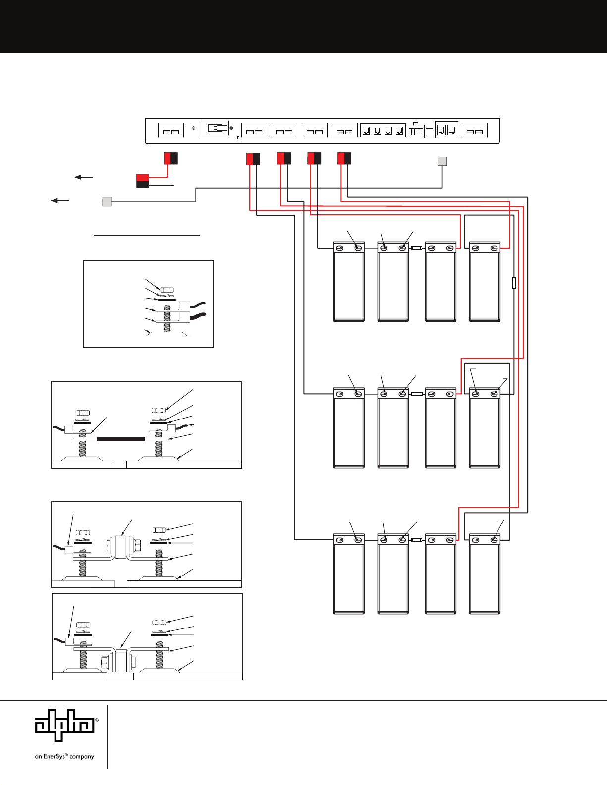
Fig. 2-9, PN-4 FT XRT Battery Installation Arrangement and Wiring Diagram
BOTTOM TRAY
BATTERY INTERFACE UNIT (BIU)
BAT 1B
BAT 3B
BAT 2B
BAT 1A
BAT 3A
BAT 2A
PTS B
PTS A
MIDDLE TRAY
100A
100A
BAT SNS
BAT SNS
BAT SNS
PowerSafe®
SBS 190F battery
AlphaCell®
210FTX battery
BAT SNS
- + - +- +
- + - + - +
TO POWER
SUPPLY
DC INPUT
TO POWER SUPPLY
BIU RS485
COMMUNICATION
CONNECTION
TO DC OUTPUT
ON BIU2
TO COM1
ON BIU2
STRING B
STRING A
STRING C STRING D
PTS A
BATTERY TEMP SENSE
PTS B PTS C PTS D
80A CB
DC OUTPUT
BAT SNS
TPR COM 1 COM 2
DC INPUT
+
-
+
-
+
-
+
-
+
-
+
-
PWR
A DCB
Precision
Temp
Sense (PTS)
Battery
Voltage
Sense
{
Battery String
Input
{
{
Circuit Breaker
{
COM
Tamper Switch
{
{
PN-4FT EXTENDED RUNTIME (XRT) SYSTEMS BATTERY ENCLOSURE
Interconnect
Bus Bar
M6 Nut
Flat Washer
Split Washer
Battery Terminal
Fused Interconnect
+-
Battery Sense
CONNECTIONS
Interconnect
+
Interconnect
Bus Bar
M6 Nut
Flat Washer
Split Washer
Battery Terminal
-
PTS
Battery Sense
Battery
M6 NUT
Split Washer
Flat Washer
(PTS or Battery Sense)
Battery Terminal
Battery Cable
100A Fuse
Interconnect
Bus Bar
M6 Nut
Flat Washer
Split Washer
Battery Terminal
+
-
Battery Sense
100A Fuse
12V BRN
12V YEL 24V GRN
24V ORG
PN-4 FT EXTENDED RUNTIME (XRT) SYSTEMS BATTERY ENCLOSURE
BATTERY INTERFACE UNIT (BIU1)
7
Alpha Technologies Services, Inc. | 3767 Alpha Way, Bellingham, WA 98226, USA
Tel.: Toll Free North America: +1 800 322 5742 | Outside US: +1 360 647 2360 | Technical Support: +1 800 863 3364
For more information visit our website at: www.alpha.com
© 2022 Alpha Technologies Services, Inc. All Rights Reserved. Trademarks and logos are the property of Alpha
Technologies Services, Inc. and its aliates unless otherwise noted. Subject to revisions without prior notice. E.&O.E.
NO-OX®is a registered trademark of Mind Head LLC.
031-00014-B1-001, Rev. A (02/2023)
Alpha Technologies Services, Inc. | 3767 Alpha Way, Bellingham, WA 98226, USA
Tel.: Toll Free North America: +1 800-322-5742 | Outside US: +1 360-647-2360 | Technical Support: +1 800-863-3364
For more information visit www.alpha.com
© 2022 Alpha Technologies Services, Inc. All Rights Reserved. Trademarks and logos are the property of EnerSys and its afliates unless otherwise
noted. The following trademarks are not the property of EnerSys: NO-OX®, Anderson™. Subject to revisions without prior notice. E.&O.E.
Fig. 2-10, PN-4 FTB XRT Wiring Diagram
BAT 1C
BAT 3D
BAT 3C
BAT 2C
BOTTOM TRAY
BATTERY INTERFACE UNIT (BIU)
BAT 1B
BAT 2D
BAT 3B
BAT 2B
BAT 1A
BAT 1D
BAT 3A
BAT 2A
PTS B PTS D
PTS C
PTS A
BAT SNS BAT SNS
MIDDLE TRAY
TOP TRAY
100A
100A
100A
100A
BAT SNS
BAT SNS
BAT SNS
BAT SNS BAT SNS BAT SNS
- +- + - + - +
- + - +- +- +
- + - + - + - +
TO DC INPUT
ON BIU1
TO COM2
ON BIU1
STRING B
STRING A
STRING C STRING D
PTS A
BATTERY TEMP SENSE
PTS B PTS C PTS D
80A CB
DC OUTPUT
BAT SNS
TPR COM 1 COM 2
DC INPUT
+
-
+
-
+
-
+
-
+
-
+
-
PWR
A DCB
Precision
Temp
Sense (PTS)
Battery String Input
Battery
Voltage
Sense
{
{
{
COM
Tamper Switch
{
{
Circuit Breaker
{
PN-4FTB EXTENDED RUNTIME (XRT) SYSTEMS BATTERY ENCLOSURE
PowerSafe
®
SBS 190F battery
AlphaCell
®
210FTX battery
Interconnect
Bus Bar
M6 Nut
Flat Washer
Split Washer
Battery Terminal
Fused Interconnect
+-
Battery Sense
CONNECTIONS
Interconnect
+
Interconnect
Bus Bar
M6 Nut
Flat Washer
Split Washer
Battery Terminal
-
PTS
Battery Sense
Battery
M6 NUT
Split Washer
Flat Washer
(PTS or Battery Sense)
Battery Terminal
Battery Cable
100A Fuse
Interconnect
Bus Bar
M6 Nut
Flat Washer
Split Washer
Battery Terminal
+-
Battery Sense
100A Fuse
24V WHT
24V GRN
24V VIO12V BLU
12V GRY
24V ORG12V BRN
12V YEL
PN-4 FTB EXTENDED RUNTIME (XRT) SYSTEMS BATTERY ENCLOSURE
BATTERY INTERFACE UNIT (BIU2)
Other EnerSys Power Supply manuals

EnerSys
EnerSys alpha APX3 Series User manual

EnerSys
EnerSys alpha LPS36 Quick start guide

EnerSys
EnerSys alpha APX3-G Series User manual

EnerSys
EnerSys Alpha Broadband UPS User manual

EnerSys
EnerSys alpha CXPS-E3 User manual

EnerSys
EnerSys alpha Cordex CXRF 48-3.6kW Quick start guide

EnerSys
EnerSys Alpha FMPS FTTP User manual


