EnerSys Alpha Broadband UPS User manual

1017-950-B1-001, Rev. A (07/2020)
Quick Start Guide
Fig. 1-1, Main features of the XM3.1-HP Series Power Supply
Introduction
This guide briefly describes the XM3.1-HP power supply and provides procedures with regard to the installation of the
power supply, battery connection, the Smart Display, initial startup and test, battery configuration and verification of
successful installation. For detailed information, refer to the XM3.1-HP Broadband UPS™ Technical Manual available at
www.alpha.com.
Audience
This guide is intended for experienced, qualified and licensed installation personnel familiar with the mechanical and
electrical requirements of enclosure and power supply systems. Review the support documentation on the website to
become familiar with the features and functions of the equipment in this system before proceeding. Failure to install
and/or use this equipment as instructed in the system documents can result in a hazard to personnel or damage to the
equipment. This system is only serviceable by qualified personnel.
1.0 Overview
The Intelligent Broadband UPS™ is comprised of the following:
Transformer Module — Acts as a stand-alone line conditioner. The transformer module contains a ferroresonant
transformer, AC oil capacitor, line isolation relay, Power Distribution Module, and EMC Filter board.
Intelligent Inverter Module — Required for standby operations and contains circuitry needed for the three-to-ve-
stage temperature-compensated battery charger, DC to AC inverter, AC line detectors and Smart Display.
Communications Module — The Communications Module is populated with the Smart AlphaGuard™ (SAG)
mounted to the Element Monitoring Module (EMM). The module also contains an embedded Cable Modem
Module (CMM) which enables status monitoring and communications. This module may also be referenced as a
"transponder" in this guide and supporting technical manuals.
A
B
C
SAG Battery Sense Harness
Required
Grounded Surge Protector
(Alpha p/n 162-028-10 or equivalent)
To HeadendRF Drop
1Output 1 (Primary) 9Battery Input
2Output 2 10 Environmental (ENV) Control Connector
3N + 1 Port 11 Smart AlphaGuard (SAG) Connector
4AC Power Input 12 SFP Optical Status Monitoring Port
5Smart Display with Softkeys 13 Ethernet (ETH) Connector
6Battery Breaker 14 Tamper (TPR) Switch Connector
7Local/Remote Indicator (LRI) Connector 15 RF Connector
8Precision Temperature Sensor (PTS) Connector
NOTICE:
Alpha recommends
tightening the RF cable
connector and the cables
attached to the Grounded
Surge Protector to a torque
setting of 10in-lb ± 1in-lb.
10
11
12
13
15
14
A B C
1
2
3
4
5
6
7
8
9
™

2017-950-B1-001, Rev. A (07/2020)
1.1 Communications Module
The Communications Module consists of the Element Monitoring Module (EMM), Cable Modem Module (CMM) and Smart
AlphaGuard™ (SAG) battery balancer. The embedded Cable Modem Module (CMM) may be ordered factory-installed or
added later to the Inverter Module by qualied personnel or Alpha®Service Depot. The CMM embedded DOCSIS®Status
Monitoring unit enables monitoring of Alpha power supplies through existing cable network infrastructure. Advanced
networking services provide quick reporting and access to critical powering information.
The CMM utilizes Simple Network Management Protocol (SNMP), standard SCTE-HMS and Alpha Management
Information Bases (MIBs) to provide network status monitoring and diagnostics. A web interface enables authorized
personnel direct access to advanced diagnostics using a common web browser. This guide pertains to all models and
standard options. Refer to the technical manual for additional details on advanced status monitoring using the SFP optical
port.
The EMM supports the Smart Display functionality and provides the communication interface between the inverter module
and the Cable Modem module. It also supports the necessary data storage and performs optional advanced AlphaAPPs
functions such as logging power supply events, utility events, and battery health analysis. Additionally, the EMM provides
the interface for the local Ethernet interface and logic for the ancillary equipment such as tamper switches.
1
3
2
4
6
1COM Indicator LED
2Cable Modem Power (PWR) Indicator
3Downstream LED
4Upstream LED
5Small Form-factor Pluggable (SFP) Port
10
11
12
13
14
15
Fig. 1-2, Communications Module Features
6Online LED
7Ethernet Status LED
8Alarm / Ready LED
9Rx/Tx Power LED
10 Environmental (ENV) Control Connector
11 Smart AlphaGuard (SAG) Connector
12 Ethernet (ETH) Connector
13 Tamper (TPR) Switch Connector
14 Reset Button
15 RF Connector for CMM
Cable Modem Module (CMM)
Element Monitoring
Module (EMM)
Smart AlphaGuard (SAG)
5
7
8
9

3017-950-B1-001, Rev. A (07/2020)
A/B [C/D] NEG
Black, Pin 5
Vbatt 3A 36V
Red, Pin 9
Vbatt 2A 24V
Orange, Pin 4
Vbatt 1A 12V
Brown, Pin 10
+
-
3A
+
-
2A
Black (String -) 0V
+
-
1A
36VDC
Red (+)
2.0 Battery Installation and Wiring
Load batteries into cabinet with the positive terminals (+)
facing forward. Coat the hardware and battery terminals
with an approved battery terminal corrosion inhibitor such as
NCP-2®and assemble the cables and hardware as shown in
the illustrations below. Torque hardware to 110 in-lbs (12.4
Nm). If M6 hardware is used, torque to 120 in-lbs (15.6 Nm).
With a Midtronics®Conductance meter (Celltron®Essential,
Celltron®Advanced or equivalent) measure the conductance
value (MHOS) of each battery and record for use in Section
6.2 Battery Conguration. Also, record the battery date code
on the battery label for entry on the DATE SET screen.
To Battery Connector
To Precision Temperature Sensor (PTS)
connector
To Smart
AlphaGuard
Connector
Verify battery voltage, cable color, connection
and polarity are correct before proceeding.
WARNING! ELECTRICAL HAZARD
Use 1/4-20 x 3/4" (19 mm) bolts for threaded insert terminals. If using a spacer for the in-line fuse link,
use 1/4-20 x 1" (25.4 mm) bolts.
CAUTION!
3.0 Output Voltage Reconguration Procedure
Tools Required:
Small at-blade screwdriver
1. To access output voltage terminal, remove the Inverter Module.
2. Loosen the terminal screw and move the output voltage wire
(Fig. 3-1) to the desired output voltage position on the terminal strip.
3. Torque the terminal block screw to 7 in-lbs (0.79 Nm) to secure the
output voltage wire.
4. Reinstall the Inverter Module.
Fig. 2-1, Battery String Wiring Diagram
Fig. 3-1, Output Voltage Terminal Positions
63V 89V
Factory Default Setting, 89V
Alternate Setting, 63V
Tighten to 7 in-lbs (0.79 Nm)
Before performing this procedure, unplug the Power
Supply from the AC power source and batteries.
WARNING! ELECTRICAL HAZARD
Fig. 2-2, Hardware Stack Up,
Non-Fused Connection
3/4" (19 mm) x
1/4-20 Bolt
Split Washer
Flat Washer
Battery Sense Cable
or PTS
Battery Cable
Battery Terminal
Nut
Split Washer
Flat Washer
Battery
Cable
In-Line Fuse Link
Flat Washer
1" (25.4 mm) or
3/4" (19 mm) x 1/4-20 Bolt
1" (25.4 mm) x
1/4-20 Bolt
Flat Washer
Split Washer
Spacer
Battery Terminal
Fuse
Fig. 2-3, Hardware Stack Up, Fused Connection
In-line
Fuse
The battery terminal hardware is subject to change based on battery make and model.
NOTICE:
4017-950-B1-001, Rev. A (07/2020)
1. After wiring battery cable kit, battery sense cables and PTS [8], as shown in Section 2,
verify DC/Battery breaker [6] is OFF.
2. Connect the Smart AlphaGuard™ (SAG) wire harness to SAG port [11].
3. Connect the Tamper Switch and RF cable to the transponder [13 and 14].
4. Verify the SPI’s (Service Power Inserter) ON / ALT Toggle Switch is in the ALT position.
5. Connect the SPI’s input cable to the Output 1 Connector [1]. If a 2nd
SPI / ALT Box is present connect input cable to Output 2 Connector [2].
6. Plug the optional Local/Remote Indicator (LRI) cable into the LRI connector [7]. For
existing LRI installations, use LRI adapter kit, p/n 875-952-20.
7. Turn AC breaker ON and verify it is the correct utility voltage at the outlet (per unit’s
nameplate voltage). If correct, plug in the XM3.1-HP line cord into the utility outlet.
8. Verify correct battery voltage and polarity on battery cable connector (see Fig. 2-1) with a
digital voltmeter; if correct, plug the battery cable connector into Inverter Module [9].
4.0 Power Supply Connections (Refer to Fig. 1-1)
Fig. 4-1, SPI toggle switch
(shown in ALT position)
ALT ON
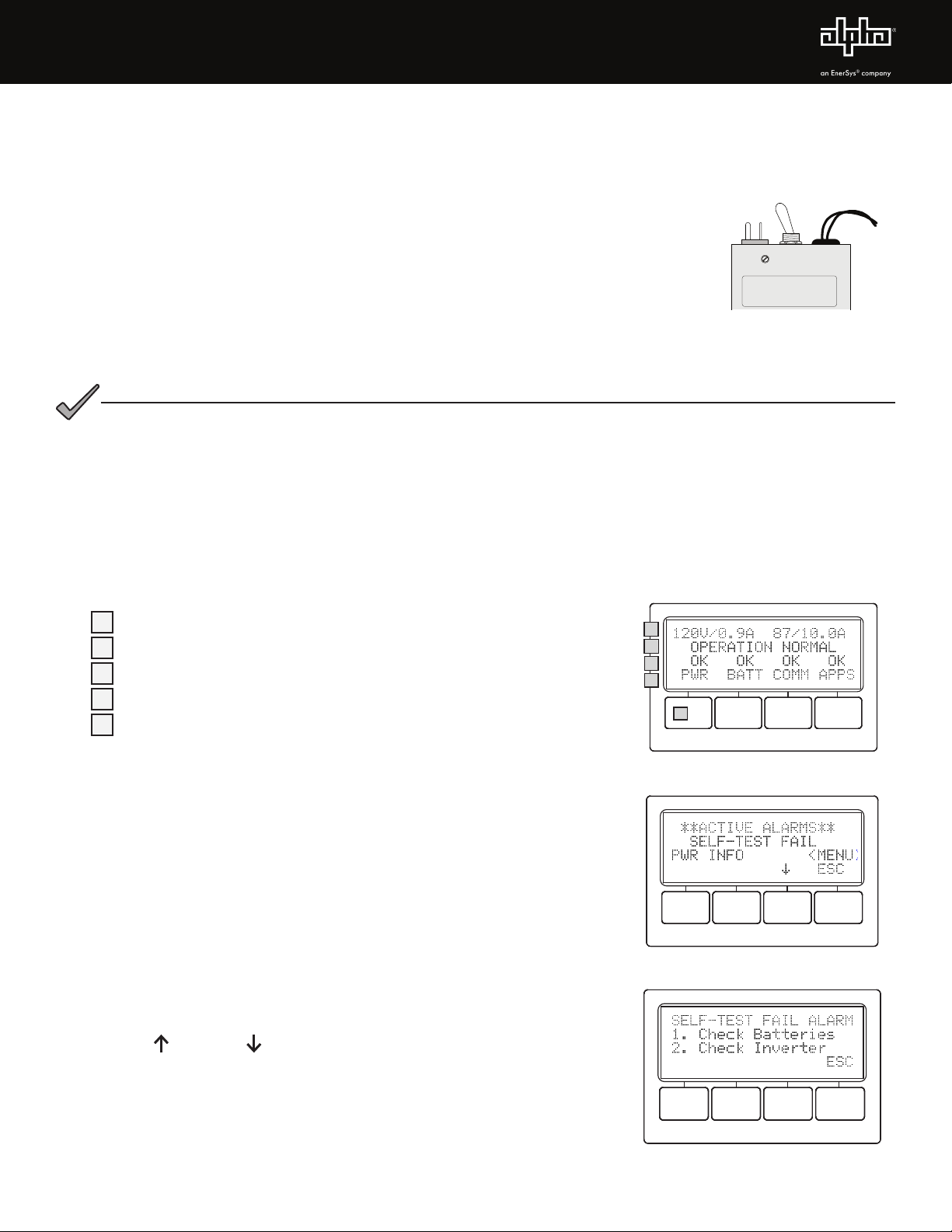
5.0 Using the Smart Display
All operational functions, system testing, menus and alarms are available via the illuminated Smart Display. Display
functions are accessible by following the indicated prompts above the four softkeys. Descriptions of the display functions
are detailed below. Press any of the softkeys to activate the Smart Display. For Smart Display functionality, an EMM
module is required to be installed in the Communications Module.
11st line: Displays Input and Output Voltage/Current
2Describes Power Supply Mode of Operation
3Describes Status of Functions
4Functionality top level menu PWR, BATT, COMM and APPS
5Softkeys (Menu-driven system conguration)
Fig. 6-2, Self-Test Fail Alarm Menu,
with suggestions for corrective actions
6.0 Startup, Battery Conguration and Self-Test
6.1 Initial startup
1. After completing all the steps in Section 4.0,Power Supply Connections,
turn the DC/Battery breaker [6] ON. The Smart Display will cycle through
its functions (approximately 60 seconds) verifying proper operation.
During this time, the XM3.1-HP may perform an automatic 5 second
Self-Test to verify whether a battery string is connected to the power
supply system by checking the battery string voltage. Upon successful
completion, the Smart Display will indicate “OPERATION NORMAL”.
From this screen, proceed to Section 6.2, Battery Conguration.
2. If power supply alarms are present and do not clear after 60 seconds,
press the softkey associated with the alarm to see the ACTIVE ALARM
list.
3. Press UP or DOWN to select the active alarm.
4. Press ENTR to select the alarm and display diagnostic information.
Press ESC to return to the alarm list. Refer to the XM3.1-HP Power
Supply Technical Manual for a complete listing of alarm conditions and
recommended diagnostic solutions.
5. Once the alarm has been cleared, the batteries can be congured in the
system as outlined in the next section.
1
4
3
5
Fig. 5-1, Smart Display with
Sample Screen
2
Fig. 6-1, Smart Display indicating a
Self-Test Fail Alarm
The power supply will boot regardless of the battery breaker position once the batteries are
connected. The inverter will not run, but the LCD screen will turn on and display instructions for
applying AC power or closing the breaker.
NOTICE:

5017-950-B1-001, Rev. A (07/2020)
6.2 Battery Conguration
1. From the Operation Normal screen, press the BATT softkey to open the BATTERY INFO menu.
2. Press ENTR to open BATT CONFIG Menu. The BATT MHOS screen opens*; press ENTR to access the rst battery
in the string, for example, (A1). The rst digit will be cycling on and o. Press the UP arrow key to set the value of
each digit as recorded at the time the batteries were installed. Once the correct value is set, press ENTR to advance
to the next digit. Use the UP arrow key as before to set the value. Repeat for each following digit. When complete,
press ENTR to return to the BATTERY MHOS screen. Press the DOWN arrow key to select the next battery in the
string and repeat the MHOS setting process.
3. Once the MHOS values for each battery have been set, press ESC to return to the BATTERY CONFIG MENU.
4. Press the DOWN arrow key to select the next line item for adjustment: BATT DATES.
5. Press ENTR to select battery and advance to DATE SET screen. Press ENTR to select Batt A1 date. Select ENTR
and key in the dates recorded from the battery labels at the time of installation. Press ESC to return to the DATE SET
screen and the down arrow to select the next battery. Repeat the above steps for each remaining battery.
6. Press DOWN arrow softkey and select BATT MODEL and from the submenu, select the battery type installed.
7. Press ENTR to return to the Battery Cong menu and select NUM BATT STRINGS and enter the correct value.
8. Press ENTR to accept new data.
9. Press ESC to return to the OPERATION NORMAL screen.
10. Switch SPI/ALT ON and verify the XM3.1-HP is supplying to the load.
Condition Output LED Alarm LED
Normal Operation On O
Minor Alarm Flash O
Major Alarm Flash Flash
Output O O Flash
OUTPUT
ALARM
TEST
A Self-Test Fail alarm will be activated and appear on the Smart Display and Transponder web page if the XM3.1-
HP detects one or more defective battery strings or problem with the Inverter Module. Replace batteries or module
as required. This is a latched alarm and power cycling the Inverter Module will not clear the alarm. This alarm can
only be cleared by successfully running in self-test for a minimum of one minute.
For power supply installations that may not have utility power available due to new construction or extended service
interruptions, it is recommended to disconnect the batteries from the power supply until the site is fully functional.
It is not recommended to have the power supply battery circuit breaker in the o position with batteries connected
and no utility power connected for extended periods of time. A warning will display on the Smart Display when this
condition is detected.
NOTICE:
NOTICE:
6.3 Self-Test Operation
The power supply should be operating correctly with no alarms present.
Use the Smart Display to verify Normal and Communication Information.
Verify Test Duration setting in the PWR CNFG menu screen.
1. Press and hold the TEST button for 1 to 2 seconds to start self-
test. The test will run for a preset time (5-180 minutes, set in the
PWR CNFG Menu). Self-test can also be entered by setting self-test
to ON in the PWR CNFG Menu. Additionally, the self-test can be
congured to perform a deep-discharge of 10%, 20%, 30%, 40% and
50% of battery capacity. When the deep discharge is complete, it will
revert back to the Timed Test.
Fig. 6-5, Test Button
Table 6-1, Alarm Indicators
* Battery MHOs and Date code should only be set after the transponder is online, as indicated by the "OL" LED showing a steady ON state.
This manual suits for next models
1
Table of contents
Other EnerSys Power Supply manuals

EnerSys
EnerSys Alpha FMPS FTTP User manual

EnerSys
EnerSys Alpha XRT-TPPL User manual

EnerSys
EnerSys alpha Cordex CXRF 48-3.6kW Quick start guide

EnerSys
EnerSys alpha LPS36 Quick start guide

EnerSys
EnerSys alpha CXPS-E3 User manual

EnerSys
EnerSys alpha APX3 Series User manual

EnerSys
EnerSys alpha APX3-G Series User manual
Popular Power Supply manuals by other brands

Videx
Videx 520MR Installation instruction

Poppstar
Poppstar 1008821 Instructions for use

TDK-Lambda
TDK-Lambda LZS-A1000-3 Installation, operation and maintenance manual

TDK-Lambda
TDK-Lambda 500A instruction manual

Calira
Calira EVS 17/07-DS/IU operating instructions

Monacor
Monacor PS-12CCD instruction manual


