EnerSys alpha APX3-G Series User manual
APX3-G Series
Non-standby Power Supplies
Installation and Operation Manual
Effective: May 2022
2 016-564-B0-001, Rev. A1 (05/2022)
Notas de seguridad y el cumplimiento
Revise los dibujos e ilustraciones que guran en este manual antes de
proceder. Si tiene alguna pregunta sobre la instalación o el funcionamiento
seguro del sistema, póngase en contacto con Alpha Technologies Services,
Inc. o con el representante más cercano de Alpha®. Guarde este documento
para futuras referencias.
Para reducir el riesgo de lesiones o muerte y para garantizar el
funcionamiento seguro y continuo de este producto, se han colocado los
siguientes símbolos en este manual. Cuando aparezcan estos símbolos,
tenga mucho cuidado y atención.
ADVERTENCIA DE RIESGO ELÉCTRICO proporciona
información de seguridad eléctrica para PREVENIR LESIONES
O LA MUERTE al técnico o usuario.
¡ADVERTENCIA! RIESGO ELÉCTRICO
ATENCIÓN proporciona requisitos especícos de regulación/del código
que pueden afectar a la ubicación de los equipos y/o a los procedimientos
de instalación.
ATENCIÓN:
AVISO proporciona información adicional para ayudar a
completar una tarea o procedimiento especíco.
AVISO:
PRECAUCIÓN proporciona información de seguridad con el n
de PREVENIR DAÑOS al material o equipo.
¡PRECAUCIÓN!
Notas de Conformidade e Segurança
Veja os desenhos e ilustrações contidos neste documento antes de
continuar. Se surgir qualquer dúvida sobre como instalar ou operar com
segurança o sistema, contate a Alpha Technologies Services, Inc. ou o
representante mais próximo da Alpha®. Guarde este documento para
futuras consultas.
Para reduzir o risco de lesões ou morte e assegurar a operação segura
continuada deste produto, os seguintes símbolos acompanham as
instruções deste manual. Ao encontrar estes símbolos, recomenda-se
maior precaução e atenção.
ALERTA DE PERIGO ELÉTRICO fornece informações elétricas
de segurança para EVITAR LESÕES OU MORTE de técnicos e
usuários.
ATENÇÃO! PERIGO ELÉTRICO
ATENÇÃO indica requisitos regulamentares ou de códigos especícos
que podem afetar a colocação do equipamento e/ou os procedimentos
de instalação.
ATENÇÃO:
AVISO fornece informações adicionais para ajudar a realizar um
procedimento ou tarefa especíca.
AVISO:
CUIDADO proporciona informações de segurança destinadas a
EVITAR DANOS ao material ou equipamentos.
ADVERTÊNCIA!
Safety Notes
Review the drawings and illustrations contained in this document before proceeding. If there are any questions regarding
the safe installation or operation of the system, contact Alpha Technologies Services, Inc. or the nearest Alpha®
representative. Save this document for future reference.
To reduce the risk of injury or death and to ensure the continued safe operation of this product, the following symbols have
been placed throughout this manual. Where these symbols appear, use extra care and attention.
ATTENTION provides specic regulatory/code requirements that may affect the placement of
equipment and /or installation procedures.
ATTENTION:
NOTICE provides additional information to help complete a specic task or procedure.
NOTICE:
ELECTRICAL HAZARD WARNING provides electrical safety information to PREVENT INJURY
OR DEATH to the technician or user.
WARNING! ELECTRICAL HAZARD
CAUTION provides safety information intended to PREVENT DAMAGE to material or
equipment.
CAUTION!

3016-564-B0-001, Rev. A1 (05/2022)
HINWEIS:
ACHTUNG enthält spezische regulatorische/rechtliche Anforderungen,
die sich auf die Platzierung von Geräten bzw. auf Installationsverfahren
auswirken können.
ACHTUNG:
HINWEIS bietet zusätzliche Informationen, die bei der Erledigung
einer bestimmten Aufgabe oder eines bestimmten Verfahrens
helfen.
STROMSCHLAGGEFAHR liefert dem Personal
Sicherheitshinweise zur elektrischen Sicherheit, um
VERLETZUNGEN ODER TOD ZU VERHINDERN.
WARNUNG! STROMSCHLAGGEFAHR
VORSICHT liefert Sicherheitshinweise zur VERMEIDUNG VON
SCHÄDEN an Material oder Ausrüstung.
VORSICHT!
Hinweise zur Einhaltung der Sicherheit
Sehen Sie sich die Zeichnungen und Abbildungen in diesem Dokument an,
bevor Sie fortfahren. Wenn Sie Fragen zur sicheren Installation oder zum
sicheren Betrieb des Systems haben, wenden Sie sich an Alpha Technologies
Services, Inc. oder an die nächstgelegene Vertretung von Alpha®. Behalten
Sie dieses Dokument zur späteren Verwendung.
Um die Verletzungs- oder Todesgefahr zu verringern und den sicheren Betrieb
dieses Produkts zu gewährleisten, wurden die folgenden Symbole in diesem
Handbuch durchgehend angebracht. Wo diese Symbole erscheinen, ist
besondere Vorsicht und Aufmerksamkeit geboten.
Remarques sur la sécurité et la conformité
Passez en revue les dessins et les illustrations contenus dans le présent
manual avant de procéder. Pour toute question concernant l’installation
ou le fonctionnement sécuritaire du système, veuillez communiquer avec
Alpha Technologies Services, Inc., ou le représentant Alpha® le plus près.
Veuillez conserver le présent document pour le consulter ultérieurement.
An de réduire le risque de blessure ou de mort, et pour assurer le
fonctionnement continu et sûr de ce produit, les symboles suivants ont été
répartis dans l’ensemble du manuel. Lorsque ces symboles sont présents,
veuillez faire preuve de plus de prudence et d’attention.
« ATTENTION » fournit des exigences réglementaires ou de codes
spéciques qui peuvent avoir un effet sur la mise en place de
l'équipement, les procédures d'installation, ou les deux.
ATTENTION:
« AVIS » fournit des renseignements supplémentaires pour aider
à terminer une tâche ou une procédure particulière.
AVIS:
PRUDENCE fournit des renseignements sur la
sécurité visant à PRÉVENIR LES DOMMAGES au
matériel ou à l’équipement.
PRUDENCE!
L'AVERTISSEMENT SUR LES DANGERS ÉLECTRIQUES
fournit des renseignements sur la sécurité électrique an de
PRÉVENIR LES BLESSURES au technicien ou à l'utilisateur,
voire LA MORT.
AVERTISSEMENT! DANGER ÉLECTRIQUE

4016-564-B0-001, Rev. A1 (05/2022)
APX3-G Series Non-standby Power Supply
Installation and Operation Manual
016-564-B0-001, Rev A1
Effective Date: May 2022
© 2022 by Alpha Technologies Services, Inc.
Disclaimer
Images contained in this manual are for illustrative purposes only. These images may not match your installation.
Operator is cautioned to review the drawings and illustrations contained in this manual before proceeding. If there are
questions regarding the safe operation of this powering system, please contact Alpha Technologies Services, Inc. or your
nearest Alpha®representative.
Alpha® shall not be held liable for any damage or injury involving its enclosures, power supplies, generators, batteries or
other hardware if used or operated in any manner or subject to any condition not consistent with its intended purpose or is
installed or operated in an unapproved manner or improperly maintained.
Contact Information
Sales information and customer service in USA
(7AM to 5PM, Pacic Time):
Complete technical support in USA
(7AM to 5PM, Pacic Time or 24/7 emergency support):
Sales information and technical support in Canada:
Website:
+1 800 863 3364
+1 888 462 7487
www.alpha.com
+1 800 322 5742

5 016-564-B0-001, Rev. A1 (05/2022)
Table of Contents
Safety Notes...........................................................................................................................................................................2
Unpacking and Inspection ......................................................................................................................................................6
General Safety Precautions....................................................................................................................................................6
Electrical Safety......................................................................................................................................................................7
Mechanical Safety ..................................................................................................................................................................7
1.0 Overview and Specications .....................................................................................................................................8
1.1 The Alpha®APX3-G Series...........................................................................................................................8
1.2 Alpha® APX3-G Series Specications ........................................................................................................10
1.3 Operating Principle.....................................................................................................................................10
1.4 Operation....................................................................................................................................................11
2.0 Installing an Alpha® APX3-G Unit ............................................................................................................................12
2.1 Enclosure Grounding..................................................................................................................................12
2.2 Pole-mount Installations .............................................................................................................................13
2.2.1 Wooden, Steel or Concrete Pole Mounting Procedure..................................................................13
2.3 Wall Mount Installations..............................................................................................................................14
2.4 Connecting an Alpha® APX3-G Unit ...........................................................................................................15
2.4.1 AC Output Connection...................................................................................................................15
2.4.2 Utility Power Connection ...............................................................................................................16
2.4.3 External Service Disconnect..........................................................................................................16
3.0 Initial Startup............................................................................................................................................................17
4.0 Troubleshooting and Repair ....................................................................................................................................18
4.1 Troubleshooting Guide ...............................................................................................................................18
4.2 Important Repair Instructions .....................................................................................................................18
4.3 Parts and Ordering Information ..................................................................................................................18
4.3.1 Ordering.........................................................................................................................................18
4.3.2 Replacement Parts ........................................................................................................................19
4.4 System Block Diagram ...............................................................................................................................19
Figures
Fig. 1-1, Alpha APX3-G Series Non-standby Power Supply (front view)................................................................................8
Fig. 1-2, Alpha APX3-G Series Non-standby Power Supply Vented Indoor Conguration (front view)..................................8
Fig. 1-3, Alpha APX3-G (608G) without cover........................................................................................................................9
Fig. 1-4, Alpha APX3-G (615G) without cover........................................................................................................................9
Fig. 1-5, Ferroresonant ‘Tank’ Circuit and Resulting Output Waveform ...............................................................................11
Fig. 1-6, Alpha APX3-G Operational Controls ......................................................................................................................11
Fig. 2-1, Grounding Enclosure..............................................................................................................................................12
Fig. 2-2, Pole-mounted Alpha APX3-G unit ..........................................................................................................................13
Fig. 2-3, Wall-mounting holes on APX3-G unit .....................................................................................................................14
Fig. 2-4, Sealing Plug Locations (Cover Removed) .............................................................................................................14
Fig. 2-5, Seizure Screw Location..........................................................................................................................................15
Fig. 2-6, Stinger Pin..............................................................................................................................................................15
Fig. 2-7, Connecting to Output Coaxial Connector...............................................................................................................15
Fig. 2-8, Utility Power Input and AC Output Connections.....................................................................................................16
Fig. 3-1, Voltage Reading Locations.....................................................................................................................................17
Fig. 4-1, APX3-G System Block Diagram.............................................................................................................................19
Tables
Table 1-1, APX3-G Series Specications .............................................................................................................................10
Table 4-1, APX3-G Replacement Parts ................................................................................................................................19

6016-564-B0-001, Rev. A1 (05/2022)
Unpacking and Inspection
Carefully remove the unit from its shipping container and inspect for damage. If items are damaged or missing,
immediately contact Alpha Technologies Services, Inc. and the shipping company. Most shipping companies have a short
claim period.
Save the original shipping container. It provides support for the unit during shipping.
If you need to return a unit for service, repackage it in its original shipping container. If you do not have the original
shipping container, repack the unit with at least 8 centimeters of shock-absorbing material to prevent shipping damage.
General Safety Precautions
To avoid injury:
• This equipment shall be installed by qualied service personnel only, according to the installation instructions provided
with each unit.
• The louvered versions are intended for indoor or outdoor installation. The mesh cover versions are intended for indoor
installation or in another enclosure.
• This equipment is intended for use in a national two wire CATV system. Line-Neutral/Ground is functional and relies
upon multi-point grounding of the end-use enclosure for safety. Acceptability of this equipment in the end-use CATV
system is to be determined by the authority having jurisdiction (AHJ) or NCB.
• Pollution Degree 3 environment, overvoltage category III. Indoor mesh cover version evaluated for max 55ºC ambient
temperature. Louvered cover version (indoor and outdoor) evaluated for use at max 40ºC ambient temperature.
• Intended to be connected to a CABLE DISTRIBUTION SYSTEM with a maximum external transient overvoltage rating
of 4000Vpk.
• Enclosure must remain locked at all times, except when authorized service personnel are present.
• Remove all conductive jewelry or personal equipment prior to servicing equipment, parts, connectors, wiring, or
batteries.
• Read and follow all installation, equipment grounding, usage, and service instructions included in this manual.
• Use proper lifting techniques whenever handling enclosure, equipment, or parts.
• Never use uninsulated tools or other conductive materials when installing, maintaining, servicing or replacing this
equipment.
Do not use popcorn-type packing material. Alpha Technologies Services, Inc. is not responsible
for damage caused by improper packing on returned units.
NOTICE:
This product and its associated hardware may contain equipment, or parts which have
accessible hazardous voltage or currents.
CAUTION!
The APX3-G unit must ship palletized at all times.
NOTICE:

7 016-564-B0-001, Rev. A1 (05/2022)
Enclosure, equipment or parts may be damaged or cause damage if used or installed
improperly.
CAUTION!
To avoid damage:
• Prior to installation, verify that the AC input voltage to the equipment matches with respect to voltage and frequency.
• Prior to installation, verify that the output voltage from the equipment matches the voltage requirements of the
connected equipment (load).
• Prior to installation, verify that the enclosure’s utility service panel is equipped with a properly rated circuit breaker for
use with the equipment inside. Refer to manufacturer’s recommendations.
• Review and upgrade utility service panel circuit breaker requirements whenever the equipment within the enclosure is
changed.
• Prior to installation, contact local utilities, local building maintenance departments, and cable/piping locator services to
ensure that installation does not interfere with existing utility or building cables/piping.
• Do not exceed the output rating of equipment. Verify load requirements prior and during connection process.
Mechanical Safety
• Power supplies can reach extreme temperatures under load.
• Use caution around sheet metal components and sharp edges.
• An accessible disconnect device needs to be provided with this product when permanently installed. If it is provided
with a power supply cord, the plug/ socket outlet needs to be readily accessible
Electrical Safety
• Lethal voltages are present within the power supply and electrical boxes. Never assume that an electrical connection
or conductor is not energized. Check the circuit with a volt meter with respect to the grounded portion of the enclosure
(both AC and DC) prior to any installation or removal procedure.
• Do not work alone under hazardous conditions.
• A licensed electrician is required to install permanently wired equipment.
• Input voltages can range up to 230VAC. Ensure that utility power is disabled before beginning installation or removal.
• Ensure no liquids or wet clothes contact internal components.
• This equipment works continuously.
• This equipment meets IP14/NEMA 3R standards with the standard cover. With a vented cover, this equipment meets
NEMA 1 (indoor) standards.

8016-564-B0-001, Rev. A1 (05/2022)
1.0 OverviewandSpecications
1.1 The Alpha®APX3-G Series
The Alpha® APX3-G non-standby power supply series provides conditioned power to signal ampliers in Cable Television
and Broadband distribution systems. The transformer is mounted directly to the chassis, and supplies the load with
current-limited, regulated AC power that is free from disturbances caused by spikes, surges and other forms of power line
transients.
This inexpensive and reliable Alpha APX3-G non-standby power supply can be mounted on a wooden, steel or concrete
pole, or mounted on a wall. It will deliver safe operation at all load conditions. The Alpha APX3-G units contain a
ferroresonant transformer, a resonant circuit capacitor, two terminal blocks, and are equipped with an input circuit breaker,
visual output "ON" indicator, output coaxial terminal, ground connection, and a pre-looped output wire for output current
measurement.
The Alpha APX3-G series, along with the entire line of Alpha power products, is designed to be one of the most rugged,
reliable, and cost-effective power supplies available. With over a million powering installations in more than 50 countries,
Alpha is one of the world’s leading suppliers of reliable communication powering and offers complete technical support
and prompt, reliable service to ensure that your power supply provides you with years of trouble-free operation. For further
information, contact Alpha or go to: www.alpha.com.
An optional mesh cover is available for all models. Units supplied with mesh covers are intended
for indoor use only. Contact your Alpha®representative for details.
NOTICE:
Fig. 1-1, Alpha APX3-G Series Non-standby Power Supply
(front view)
Fig. 1-2, Alpha APX3-G Series Non-standby
Power Supply Vented Indoor Conguration
(front view)

016-564-B0-001, Rev. A1 (05/2022) 9
1.0 Overview and Specications, continued
Fig. 1-3, Alpha APX3-G (608G) without cover
Fig. 1-4, Alpha APX3-G (615G) without cover
LEFT FRONT
FRONT
LEFT
RIGHT
RIGHT

10 016-564-B0-001, Rev. A1 (05/2022)
1.0 Overview and Specications, continued
1.2 Alpha®APX3-GSeriesSpecications
1.3 Operating Principle
The APX3-G Series non-standby power supply utilizes ferroresonant transformer technology to provide line conditioning
and voltage regulation. The primary and secondary windings of the transformer are physically isolated from each other by
a large steel core which signicantly reduces the capacitive coupling of spikes and noise to the secondary winding. This
provides a regulated, current-limited output with excellent isolation and noise attenuation: 140dB common mode; 80dB
transverse mode.
An oil-lled resonant AC capacitor is connected to the resonant (secondary) winding of the transformer forming a tank
circuit. This provides the resonant circuit function which contributes to the voltage regulation of the supply. The advantage
of this type of transformer/capacitor design is the ability of the ferroresonant transformer to regulate its output voltage
over a wide range of input voltages and output loading. Typical output voltages may vary + 5% with 87% efciency, with
input voltage variations of + 20% of nominal line voltage, and output loading of 20% to 100%. This tight regulation is
advantageous in cable television applications as the active devices are protected from dangerous voltage uctuations.
Another unique feature of the ferroresonant transformer is its ability to provide current limiting in the event of a short-
circuit. This effect is called foldback. The transformer’s output current can typically reach 150% of the nameplate output
current rating for a short period of time without damage to the transformer. When the transformer reaches the saturation
point, the output current will decrease (foldback on itself) to a minimum value, and thereby provide current limiting.
Designs based on a ferroresonant transformer are extremely rugged and reliable, and offer many years of trouble-free
operation.
Alpha® non-standby power supplies are extremely efcient, and have a typical efciency rating of >87% at full load.
Model Input Voltage Frequency Output Voltage Max. Output Current
608G 176 - 276VAC 50Hz ±3% 59.9 - 66.2VAC / 45.6 - 50.4VAC 8A
615G 176 - 276VAC 50Hz ±3% 59.0 - 66.2VAC / 45.6 - 50.4VAC 15A
EnvironmentalSpecications
Operating temperature range (Standard Outdoor) Agency compliance: -40°C to 40°C
Design limit: -40°C to 50°C
Operating temperature range (Vented Indoor) Agency compliance: -40°C to 55°C
Design limit: -40°C to 60°C
Humidity rating 95% (non-condensing)
MechanicalSpecications
Weight Audible Noise
(Standard Outdoor Conguration)
Audible Noise
(Vented Indoor
Conguration)
Model 608G (Standard) 12.5kg <45dBA
Model 608G (Mesh) 12.2kg <43dBA
Model 615G (Standard) 15.0kg <45dBA
Model 615G (Mesh) 14.7kg <43dBA
Dimensions, overall (H × W × D) 333mm × 170mm × 240mm
An optional mesh cover is available for all models. Units supplied with mesh covers are intended
for indoor use only. Contact your Alpha®representative for details.
NOTICE:
The APX3-G unit must ship palletized at all times.
NOTICE:
Table 1-1, APX3-G Series Specications

016-564-B0-001, Rev. A1 (05/2022) 11
1.0 Overview and Specications, continued
1.4 Operation
Fig. 1-5, Ferroresonant ‘Tank’ Circuit and Resulting Output Waveform
Fig. 1-6, Alpha APX3-G Operational Controls
The output waveform from the ferroresonant transformer is not a true sine or square wave, but is instead a quasi-square
wave.
Ferroresonant
transformer and AC
capacitor
C1
T1
Noisy input
waveform Clean output
waveform
It is necessary to use a true RMS voltmeter to correctly measure the output voltages.
NOTICE:
All controls and indicators for the Alpha APX3-G unit, except the input circuit breaker, are
accessible on the faceplate of the unit.
NOTICE:
Input Circuit Breaker
Input Cable Gland
Output Indicator
Light
Ground Stud
Output Coaxial Connector

12 016-564-B0-001, Rev. A1 (05/2022)
2.0 Installing an Alpha®APX3-G Unit
2.1 Enclosure Grounding
Fig. 2-1, Grounding Enclosure
Service Drop
To Service Entrance
Meter
Copper Ground Rod
12.7mm × 2.4m (1/2" × 8')
Service Entrance
Mounting Bracket
APX3-G
#8 AWG (Minimum)
Copper Ground Wire
Output Coaxial Cable
Utility Power Input
(From Service Entrance)
Alpha® recommends using the grounding method illustrated below. The grounding method may vary depending on
local codes and other site-specic characteristics.
NOTICE:

016-564-B0-001, Rev. A1 (05/2022) 13
2.0 Installing an Alpha® APX3-G Unit, continued
2.2 Pole-mount Installations
The Alpha® APX3-G series non-standby power supplies are designed to mount on a wooden, steel or concrete pole or
wall. When installing an Alpha APX3-G unit on a pole, an approved mounting strap must go through the mounting slots of
the unit and around the pole (straps must be stainless, galvanized or equivalent). When installing on a wall, use four 8mm
lag bolts. Most regulatory agencies require the base of the unit to be at a minimum height from the ground.
2.2.1 Wooden, Steel or Concrete Pole Mounting Procedure
Required Tools and Materials:
• Two customer-supplied pole straps of an appropriate width to t through the mounting slots of the unit and appropriate
length to t around the pole. Straps must meet code requirements, be stainless, galvanized or equivalent, and be able
to support the unit for the anticipated lifetime.
• Assorted screwdrivers, sockets or wrenches.
Procedure:
1. Unpack the unit.
2. Thread the pole-mounting straps through the unit’s strap slots.
3. Position the unit onto the pole and fasten straps.
4. Tighten straps according to strap manufacturer’s specications.
5. Trim any excess strapping material.
Fig. 2-2, Pole-mounted Alpha APX3-G unit
Mounting Slots
Verify height restrictions and allowances before installing an Alpha®APX3-G unit.
NOTICE:
Install this equipment strictly according to installation instructions. The faceplate must face
downward in order to meet the Type 3R Rainproof requirements.
NOTICE:
Water splashing upwards into the cutouts or louvers may ood the interior of the enclosure
causing unpredictable shorting or electrical failure.
CAUTION!
14 016-564-B0-001, Rev. A1 (05/2022)
2.0 Installing an Alpha® APX3-G Unit, continued
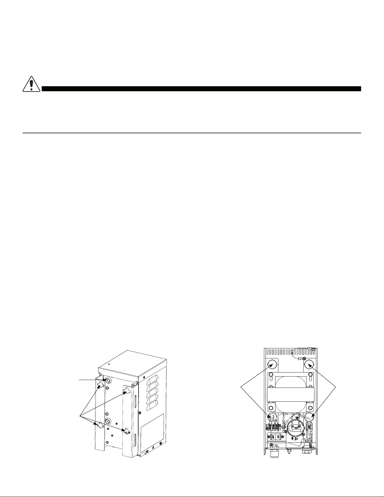
Fig. 2-3, Wall-mounting holes on APX3-G unit Fig. 2-4, Sealing Plug Locations (Cover Removed)
2.3 Wall Mount Installations
For wall mounting, securely fasten the unit to the wall with four 8mm lag bolts of appropriate grade and material to support
the unit.
Required Tools and Materials:
• Four customer-supplied stainless steel M8 × 90mm long (or larger) lag bolts
• Four customer-supplied stainless steel M8 flat washers, 24mm max. diameter × 2mm min. thickness
• Ratchet w/ 13mm socket
• Level
• Stud nder (optional)
• Drill w/ 5mm drill bit
• Tape measure
• Assorted screwdrivers (#2 Phillips head, #2 Standard head)
Procedure:
1. Unpack the unit.
2. Remove the four securing screws from the exterior sides of the cover, loosen the two retaining screws and remove the
cover from the chassis.
3. Place the APX3-G template (located on last page of this manual) at the required height for mounting and mark the
location of the mounting holes.
4. With the 5mm drill bit, drill the four holes for mounting.
5. Screw the four lag bolts with washers into the mounting surface. Leave approximately 2-3mm between the screw
head and mounting surface.
6. Remove the sealing plugs in the front of the mounting holes.
The populated cabinet weighs approximately 16kg (35.4 lbs). Installer needs to ensure the wall is
capable of supporting the loaded enclosure. Direct mounting to wall studs and 19mm (3/4") plywood
backing is required.
CAUTION!
Before installing an enclosure, the location and method of mounting must be approved by the utility.
ATTENTION:
Sealing
Plugs
Sealing
Plugs
Mounting
Holes
Sealing
Plugs (×4)

016-564-B0-001, Rev. A1 (05/2022) 15
2.0 Installing an Alpha® APX3-G Unit, continued
Fig. 2-5, Seizure Screw Location
Fig. 2-6, Stinger Pin
Fig. 2-7, Connecting to Output
Coaxial Connector
• Failure to replace the sealing plugs will allow moisture to enter the enclosure and damage
equipment.
• Install this equipment strictly according to installation instructions.
• The faceplate must face downward in order to meet the rainproof requirements for pole-
mount installation.
CAUTION!
7. Align the APX3-G unit mounting holes over the lag bolts with at washers and slide the chassis downward into the
slots. Securely tighten the top lag bolts by inserting the ratchet and socket through the access holes in the back of the
chassis. Replace the four sealing plugs, making sure they properly t.
8. Continue to Section 2.3.1, AC Output Connection.
31.7cm (1.25”)
2.4 Connecting an Alpha®APX3-G Unit
2.4.1 AC Output Connection
Required Tools:
• Appropriate open-end wrenches and screwdrivers
1. Prepare the incoming coaxial cable used for the distribution of power
(including external ttings not supplied by Alpha®).
2. Loosen the seizure screw output tting to accommodate the center pin
("stinger") of the cable connector.
3. Screw the cable connector into the output port (large hex nut tting)
located on the baseplate of the Alpha APX3-G unit. Make sure that
the center pin extends far enough into the tting so that the seizure
assembly can be secured.
4. Tighten the brass seizure screw on the cable "stinger" or center
conductor to 2.82Nm (25in-lb).
5. Connect line cords for utility power. See Section 2.4.2, Utility Power
Connection for detail.
6. Replace cover and securely tighten cover securing and retaining
screws.
7. Choose the right tie-in for power from the terminal block of the
transformer. For the APX3-608G and APX3-615G units, the output
default is 63V. Ensure power is OFF when changing the output tie-in.
The center conductor may be trimmed to allow for a ush
t. The length of the center conductor must be 31.7cm
(1.25”) from the end to the center of the O-Ring.
NOTICE:
Seizure Screw

16 016-564-B0-001, Rev. A1 (05/2022)
2.0 Installing an Alpha® APX3-G Unit, continued
2.4.2 Utility Power Connection
The APX3-G unit is not supplied with a line cord to allow the installer to select the most suitable cord and plug for the
installation (#14 AWG is recommended). The power cord is installed as indicated in Fig. 2-8 above. The cable tting is
equipped with a strain relief clamp and spade crimp connectors for secure attachment of the line cord. Three spade crimp
connectors are provided with the APX3-G unit for connecting the line cord to the input terminal block. The installer must
strip the line cord wires and crimp the spade connectors onto the ends of the wires before terminating to the terminal
block. Alpha recommends a portable crimping tool such as the TE 47387.
2.4.3 External Service Disconnect
When installing an external service disconnect, install it between the utility power connection and the Alpha APX3-G unit.
(The customer supplies the external service disconnect. Please consult manufacturer or local power utility company for
specic installation instructions and guidelines.)
For pole-mount enclosures, attach directly to utility pole. (See Section 2.2.1, Wooden, Steel or Concrete Pole Mounting
Procedure.)
Fig. 2-8, Utility Power Input and AC Output Connections
Ensure the tightness of the seizure screw for the cable "stinger." Arcing may occur because
of a loose connection. During routine maintenance, always check the seizure screw
assembly to ensure that it is tight. Alpha® is not responsible for damage to equipment or
personnel because of incorrect taps or loose connections.
WARNING! ELECTRICAL HAZARD
To change voltage outputs from 63V to 48V (see Fig. 2-8 above), select the appropriate tie-in,
then tighten the screws on the terminal block.
NOTICE:
If installing an external breaker, use a “high magnetic” trip breaker rated for 220/240VAC, 10A
(for 608G and 615G) normally used in HVAC (Heating, Ventilation, Air Conditioning) applications
to accommodate the high-inrush currents associated with the start-up of ferroresonant
transformers (400 Amp, no-trip, rst-half cycle).
NOTICE:
L N 48V 63V
Cable Fitting for AC Line Cord
Utility Power Input
Terminal Block
Output Terminal
Block
016-564-B0-001, Rev. A1 (05/2022) 17
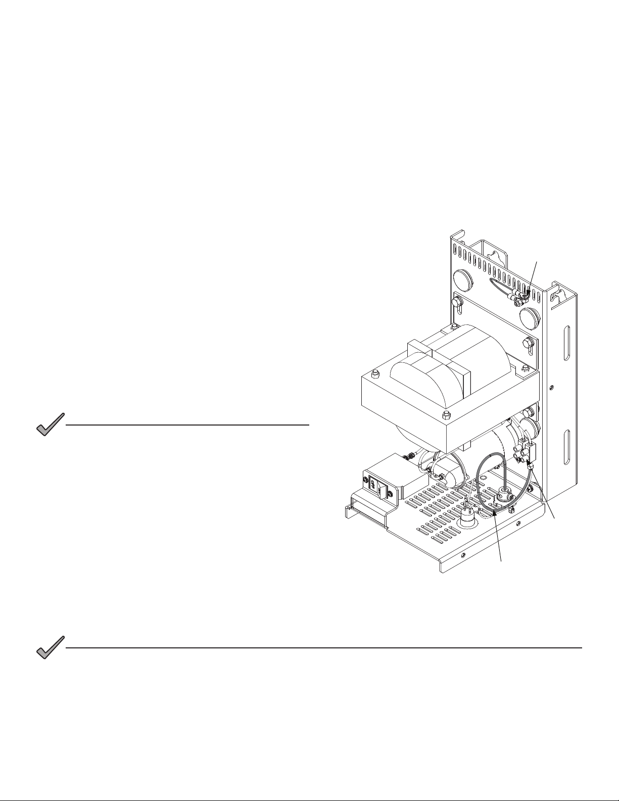
3.0 Initial Startup, continued
Procedure:
1. Before applying power, ensure that the AC LINE input
breaker is in the OFF position.
2. If present, switch the external service entrance breaker
(located outside of the enclosure) to ON.
3. Activate the Alpha APX3-G unit by pressing the input
switch to ON.
4. Use a true RMS voltmeter to measure the output voltage
of the Alpha APX3-G unit by placing the multimeter
positive probe on the output terminal block screw and
negative probe on the ground stud located at the top
of the APX3-G unit (see Fig. 3-1). The voltage will read
between 59.9V and 66.2VAC (608G), and 59V and
66.2V (615G) for 63VAC output.
5. The APX3-G unit is equipped with a pre-looped wire for
output current measurements, as shown in Fig. 3-1. Use
the AC current clamp meter on the pre-looped wire to
measure the current. The current draw must not exceed
8A (maximum) for the APX3-608G model, and 15A
(maximum) for the APX3-615G model.
6. Remove power from unit.
7. Install and close the cover on the Alpha APX3-G unit.
Secure the retaining screw and lock the enclosure.
Fig. 3-1, Voltage Reading Locations
3.0 Initial Startup
The Alpha® APX3-G unit must be tested before it is placed into service. Once utility and cable connections have been
made, testing may begin.
Required Tools:
• True RMS voltmeter
• AC current clamp meter
If you use a non-RMS type voltmeter, the
reading can be off by as much as 10% due
to the “quasi” square-wave output of the
ferroresonant transformer.
NOTICE:
If the unit is noisy after Step 6, remove the cover, then make sure it aligns with the side rails as
you again replace the cover. Also, the side securing screws may be re-installed to further secure
the cover.
NOTICE:
Pre-looped Wire
Output
Terminal Block
Screw
Ground Stud

18 016-564-B0-001, Rev. A1 (05/2022)
4.0 Troubleshooting and Repair
4.1 Troubleshooting Guide
The troubleshooting guide is designed to display typical symptoms, causes and solutions, beginning with the most obvious
and working systematically through the unit. Alpha Technologies Services, Inc. recommends that the power supply
maintenance log accompany units brought in for bench service to aid the technician in troubleshooting the problem.
4.3 Parts and Ordering Information
4.3.1 Ordering
To order parts, contact the Alpha Technologies Services, Inc. Customer Service Department directly at:
To obtain emergency technical support (7 days/week, 24 hours/day) call:
To nd additional information about Alpha products, services, and ofce locations, go to: www.alpha.com.
Returns must be prepaid and insured. Alpha® does not accept COD and freight collect. Alpha
Technologies Services, Inc. does not assume responsibility for damage caused by improper
packing of returned units.
NOTICE:
Latin America: +1 360 647 2360 United Kingdom: +44 1279 422110
Germany: +49 9122 79889 0 Middle East: +357 25 375675
Australia: +61 2 9894 7866 China: +86 10 5462 6760
Rest of Asia: +1 360 647 2360
Western/Eastern Europe: +49 9122 79889 0
China: +86 10 8462 6760
U.S.: +1 360 647 2460
Symptom Probable Cause Remedy
No output to cable
(no AC line power)
• Utility power outage
• AC power cord unplugged
• AC input circuit breaker tripped
• Use voltmeter to verify 220VAC / 230VAC at receptacle
• Plug in AC power cord
• Reset AC circuit breaker
No output to cable. • Local seizure screw
• Poor connection at cable output connector
• Loose connection at transformer lug
• Tighten seizure screw
• Check connector
• Check connection
Incorrect output voltage. • Incorrect type of voltmeter used.
• Under-loaded output (608G<1A) (615G<1.5A)
• Over-loaded output
• Faulty tank circuit capacitor (may appear swollen
or distorted; may leak oil).
• Use a TRUE RMS meter
• Correct or increase load
• Reduce load
• Replace capacitor, C1
4.2 Important Repair Instructions
Before returning a unit to Alpha Technologies Services, Inc. for repair, contact the nearest Alpha® repair facility, technical
support or sales ofce to obtain a Return Material Authorization (RMA) number. The RMA must be clearly marked on the
unit’s original shipping container. If the original container is no longer available, pack the unit in at least 3 inches of shock
absorbent material (do not use popcorn-type material for packaging), and clearly mark the RMA on the outside of the
shipping container.

016-564-B0-001, Rev. A1 (05/2022) 19
4.0 Troubleshooting and Repair, continued
4.3.2 Replacement Parts
The following parts can be replaced in the eld and are available from Alpha Technologies Services, Inc. To order parts,
please specify the model number which appears on the nameplate, and contact your nearest Alpha sales ofce.
4.4 System Block Diagram
Fig. 4-1, APX3-G System Block Diagram
Table 4-1, APX3-G Replacement Parts
Alpha p/n Type Description
210-079-18-001 Capacitor Oil Filled 15µF; 660VAC
Ground G
L
N
Line
Neutral
Pre-looped wire for output
current measurement Terminal
Block
Terminal
Block Circuit
Breaker
Output
Indicator
Output
Coax
Connector
63VAC Out
63VAC
48VAC Out
48VAC
Oil
Capacitor
Ferro
Transformer
Oil
Capacitor
Pre-looped wire in
unit reference

114mm
163mm
Mounting Template:
Mark the holes and position the drill according
to the mounting hardware.
Remove the black plastic plugs in order to
tighten the mounting hardware. Please replace
the plugs after tightening hardware.
This manual suits for next models
2
Table of contents
Other EnerSys Power Supply manuals

EnerSys
EnerSys alpha CXPS-E3 User manual

EnerSys
EnerSys alpha APX3 Series User manual

EnerSys
EnerSys alpha Cordex CXRF 48-3.6kW Quick start guide

EnerSys
EnerSys alpha LPS36 Quick start guide

EnerSys
EnerSys Alpha FMPS FTTP User manual

EnerSys
EnerSys Alpha XRT-TPPL User manual

EnerSys
EnerSys Alpha Broadband UPS User manual
Popular Power Supply manuals by other brands

Whelen Engineering Company
Whelen Engineering Company VPPS2C installation guide

BEHLMAN
BEHLMAN BL15000 Series User's guide and technical reference manual

INIM
INIM IPS12060G quick start guide

Cisco
Cisco PWR-7513-AC Replacement instructions

Spellman
Spellman BERTAN 602C-10P instruction manual

Weather X
Weather X WR882R user guide


