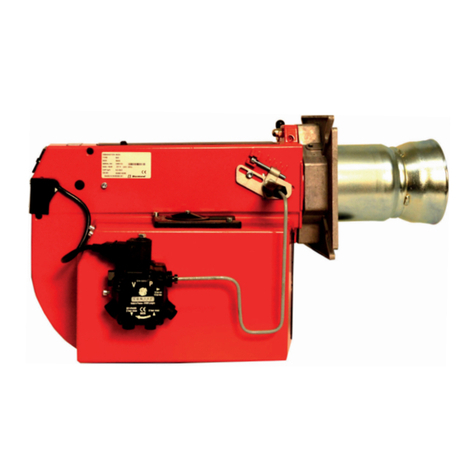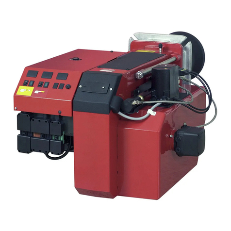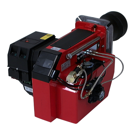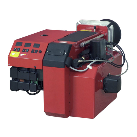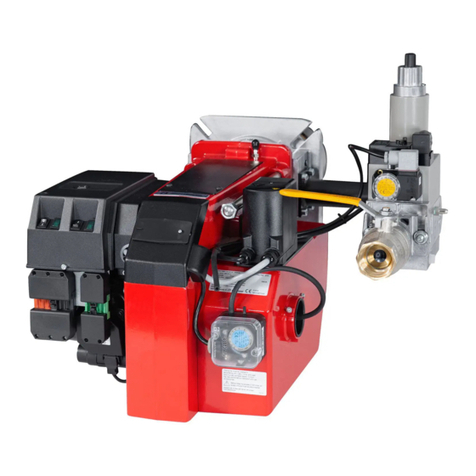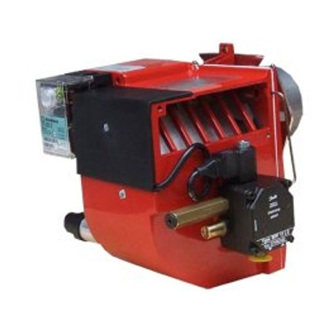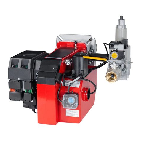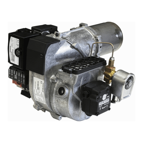
3Bentone BFG1
General
Table of contents
GENERAL
1. General Information_______________________________________________________4
Safety instructions ______________________________________________________4
Actions to take if you smell gas____________________________________5
Burner servicing schedule ___________________________________________6
Component replacement intervals________________________________6
Delivery check____________________________________________________________6
2. Technical data _______________________________________________________________7
2.1 Burners are intended for use at:_________________________________7
2.2 Dimensions _____________________________________________________________7
1.0.1 Dimensions flanges________________________________________7
2.3 Capacity range BFG1 H3 __________________________________________8
2.3.1 Gas categories, approved gases_____________________9
2.3.2 Electric Specification EN 60335-2-102 ____________9
2.4 Model BFG1-2 H3__________________________________________________ 10
2.4.1 Burner output/ Basic settings_______________________ 10
2.5 Description ____________________________________________________________11
2.5.1 Components_______________________________________________12
3. Installation __________________________________________________________________ 13
3.1 Skeleton diagrams _________________________________________________ 13
3.2 Delivery check _______________________________________________________ 14
3.3 Preparations for installation_____________________________________14
3.4 Gas supply ____________________________________________________________14
3.5 Electric connection_________________________________________________ 14
3.6 Setting brake plate and air flow________________________________ 14
3.7 Burner installation___________________________________________________ 15
3.7.1 Hole pattern________________________________________________ 15
3.7.2 Burner installation________________________________________ 15
3.7.3 Gas connections _________________________________________15
3.7.4 Electric connection ______________________________________15
3.8 Control measures___________________________________________________ 16
3.8.1 Gas quality _________________________________________________16
3.8.2 Bleeding_____________________________________________________16
3.8.3 Function test_______________________________________________16
3.8.4 Leakage testing___________________________________________ 16
3.9 Recommended excess air when using default setting 17
3.10 Determining the gas quantity for the system______________17
3.10.1 Example of how to calculate the gas quantity
(natural gas G20): _____________________________________________18
3.11 Calculating the quantity of gas supplied____________________19
3.11.1 Nozzle assembly adjustment ________________________20
3.11.2 Air intake adjustment ___________________________________20
3.11.3 Procedure for setting the amount of air __________ 20
3.11.4 Inlet cone, air control ___________________________________21
3.11.5 Rotation of the air intake ______________________________ 21
3.11.6 Air duct ______________________________________________________ 21
4. Burner Service ____________________________________________________________ 22
4.1 Service__________________________________________________________________ 22
4.1.1 Combustion device service___________________________ 22
4.1.2 Fan motor replacement________________________________23
4.1.3 Air intake and inlet cone service ____________________24
4.1.4 Fan wheel check _________________________________________ 25
4.1.4.1 Inspection ______________________________________________25
4.1.5 Fan wheel service________________________________________ 25
4.1.6 Electrical package _______________________________________26
4.1.6.1 Complete electrical package replacement _____________26
4.1.6.2 Single electrical package component replacement ____27
4.1.6.3 Replacing the damper motor___________________________ 27
4.2 Multiblock MB-ZRDLE 405-412_______________________________ 28
4.2.1 Pressure taps______________________________________________ 30
4.2.2 Electrical connection____________________________________30
5. General instructions ____________________________________________________31
5.1 Flame monitoring and ionisation current check __________31
5.1.1 Flame monitoring ionisation __________________________ 31
5.1.2 UV –detector (QRC)_____________________________________31
5.1.3 Flame monitoring UV-detector (QRC)_____________31
5.1.4 Setting of air pressure switch________________________32
5.1.5 Setting gas pressure switch min____________________ 33
5.1.6 Setting gas pressure switch max___________________33
5.1.7 Handing over of the installation _____________________34
6. Electric equipment LME...____________________________________________ 35
6.1 Wiring diagram ______________________________________________________35
6.1.1 List of components______________________________________36
6.1.2 Function LME...___________________________________________36
6.2 Control program at faults; fault mode indicator LME .... _
37
6.2.1 Colour codes ______________________________________________37
6.2.1.1 Diagnosing alarm causes_______________________________37
6.2.1.2 Limiting of starting repetitions __________________________37
6.2.1.3 Alarm code table _______________________________________38
6.2.1.4 Interface diagnostics ___________________________________38
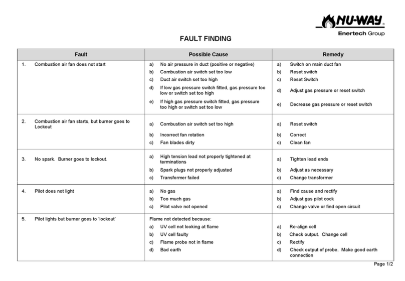
7. Troubleshooting __________________________________________________________ 39
Gas Burner______________________________________________________________ 39
8. DECLARATION OF CONFORMITY _______________________________42
9. General instructions for gasburners_____________________________43
9.2.1 Installation __________________________________________________43
9.2.2 Maintenance_______________________________________________ 43
9.2.3 If the burner has stopped _____________________________ 43
9.2.4 Shut-Off _____________________________________________________43
9.2.5 Warning______________________________________________________ 43


