manuals.online logo
Brands
  1. Home
  2. •
  3. Brands
  4. •
  5. Hobo
  6. •
  7. Accessories
  8. •
  9. Hobo RXW-UC Series User manual

Hobo RXW-UC Series User manual

RXW Pulse Input Sensor (RXW-UCx-xxx) Quick Start
23965-C MAN-QSG-RXW-UCx
Adding a Sensor Node to the HOBOnet® Wireless Sensor Network
Important: Keep the sensor node near the station while completing
these steps.
If you are setting up a new station, follow the instructions in the
station quick start guide before setting up this sensor node (go to
www.onsetcomp.com/manuals/24500-rx2105-and-rx2106-manual
for RX2105 and RX2106 stations or
www.onsetcomp.com/manuals/rx3000-qsg for RX3000 stations).
1
2
3
4 Watch the sensor node LCD during the process of joining the
network:
5
6 Go to www.hobolink.com to monitor
sensor node status and health. See the
HOBOlink Help for details.
Press the Search button. The magnifying glass icon blinks while the
station is in search mode waiting for sensor nodes to join the network.
Press the Select button on the station to switch to the module with
the manager (module 2 on RX2105 or RX2106 stations).
Open the sensor node door and install the rechargeable
batteries. Press this button on the sensor node for 3 seconds.
Press the Search button on the station again to stop the
search for sensor nodes.
This signal strength icon
blinks while searching for
a network.
Once a network is found, the
icon stops blinking and the
bars cycle from left to right.
a. b.
c. d.
This network connection
“x” icon blinks while the
sensor node completes
the registration process,
which may take up to
five minutes.
Once the sensor node has
finished joining the network, the
“x” icon is no longer displayed
and the channel count on the
station LCD increases by two
(one for the pulse input sensor
and one for the sensor node
battery).
1-800-LOGGERS 2 www.onsetcomp.com
Installing the Bracket and Sensor Node
1
Orient the bracket so the text TOP is facing
upwards.
2
To install the bracket onto a wall, use
the two long screws included in the
package. Screw the bracket to a wall
using the two holes on the mid-section
of the bracket.
3
To install the bracket
onto a pole, slip a cable
tie through each of the
channels on the bracket
and fasten the tie
around the pole.
4
Insert the bottom of the
sensor node into the retaining
clips on the bottom of the
bracket then press the top of
the sensor node into the clips
at the top of the bracket.
5
Use the short screw
included in the package to
fasten the sensor node to
the bracket.
6 Close the sensor node and use a padlock to keep it secure.
Note: Ensure that the node seal is clean from foreign
debris.
1-800-LOGGERS (564-4377) • 508-759-9500
www.onsetcomp.com/support/contact
© 2022 Onset Computer Corporation. All rights reserved. Onset, HOBO, and HOBOlink are registered trademarks of Onset
Computer Corporation. All other trademarks are the property of their respective companies.
This product has been manufactured by Onset Computer Corporation and in compliance with Onset’s ISO 9001:2015 Quality
Management System.
23965-C MAN-QSG-RXW-UCx
Mounting and Positioning the Sensor Node
•Position the sensor node towards the sun, making sure the solar panel is oriented so that it receives optimal sunlight throughout each
season. It may be necessary to periodically adjust the sensor node position as the path of the sunlight changes throughout the year or
if tree and leaf growth alters the amount of sunlight reaching the solar panel.
•Make sure the sensor node is mounted a minimum of 1.8 m (6 feet) from the ground or vegetation to help maximize distance and
signal strength.
•Consider using plastic poles such as PVC to mount the sensor node as certain types of metal could decrease the signal strength.
•Place the sensor node so there is full line of sight with the next sensor node. Use a repeater if there is an obstruction between sensor
nodes.
•There should not be more than five sensor nodes in any direction from a repeater or the manager. Data from sensor nodes travels or
“hops” across the network and may not reach the station if the sensor node is more than five hops away.
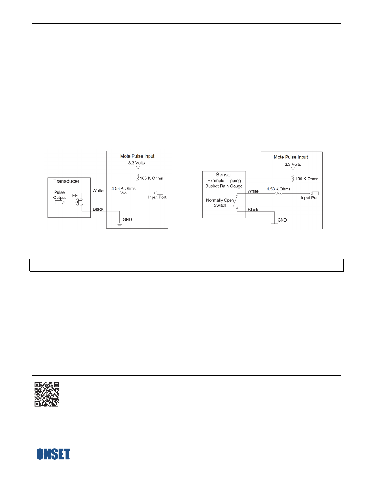
Input Connections
The pulse input sensor has two input connections. The white wire (+) is powered at 3.3 V through a 100 KΩresistor. This power is
supplied from the sensor node battery. The black wire (-) is connected to the sensor node’s ground connection. The input cable can be
connected directly to screw terminals on the sensor or to sensor cables with the included wire nuts.
Wiring for RXW-UCC Pulse Input Wiring for RXW-UCD Pulse Input
Connection Using Wire Nuts
Important: If using wire nuts, make sure the connection is protected from the elements.
1. Strip 1 cm (0.39 in.) of insulation from the end of wires, taking care not to nick the metal conductors.
2. Twist the stripped wires together clockwise and then screw on the wire nut clockwise.
3. Check the connection by gently pulling on the wires to verify a solid mechanical connection. Always strain-relief the connection to
make sure that the connection is not broken by being jerked or repeatedly worked back and forth.
Pulse Input Sensor Mounting Guidelines
•Coil and secure excess cable with cable ties.
•If cable is on the ground, use a conduit to protect against such things as animals, lawn mowers, and exposure to chemicals.
•When making a connection to a third-party sensor, take time to make sure that the connection is reliable and protected from rain,
dirt, and direct exposure to the elements. Refer to the manufacturer’s product documentation for additional information on
system configuration.
For specifications, complete mounting guidelines, and other details about this sensor node, refer to the full product manual. Scan the code
at left or go to www.onsetcomp.com/support/manuals/23966-rxw-ucx-manual.

This manual suits for next models

4

Other Hobo Accessories manuals

Hobo RX3000 Series User manual

Hobo

Hobo RX3000 Series User manual

Hobo S-LIA-M003 User manual

Hobo

Hobo S-LIA-M003 User manual

Hobo RXW 10HS User manual

Hobo

Hobo RXW 10HS User manual

Hobo RXW-SPER Series User manual

Hobo

Hobo RXW-SPER Series User manual

Hobo S-WCG-M003 User manual

Hobo

Hobo S-WCG-M003 User manual

Hobo RXW-GP3 Series User manual

Hobo

Hobo RXW-GP3 Series User manual

Hobo RXW-THC Series User manual

Hobo

Hobo RXW-THC Series User manual

Hobo WELL-CAP-02 User manual

Hobo

Hobo WELL-CAP-02 User manual

Hobo RXW-WCF Series User manual

Hobo

Hobo RXW-WCF Series User manual

Hobo RXW-THC-B Series User manual

Hobo

Hobo RXW-THC-B Series User manual

Hobo RXW TEROS-12 User manual

Hobo

Hobo RXW TEROS-12 User manual

Hobo HOBOnet RXW-THC-B Series User manual

Hobo

Hobo HOBOnet RXW-THC-B Series User manual

Hobo S-RGx-M002 User manual

Hobo

Hobo S-RGx-M002 User manual

Hobo S-LIA-M003 User manual

Hobo

Hobo S-LIA-M003 User manual

Hobo S-LWA-M003 User manual

Hobo

Hobo S-LWA-M003 User manual

Hobo RX User manual

Hobo

Hobo RX User manual

Hobo RXW series User manual

Hobo

Hobo RXW series User manual

Hobo S-LIA-M003 User manual

Hobo

Hobo S-LIA-M003 User manual

Hobo Davis S-RGE-M002 User manual

Hobo

Hobo Davis S-RGE-M002 User manual

Popular Accessories manuals by other brands

LCJ CAPTEURS CV7-BG manual

LCJ CAPTEURS

LCJ CAPTEURS CV7-BG manual

Bosch Rexroth ActiveMover Assembly instructions

Bosch

Bosch Rexroth ActiveMover Assembly instructions

Logitech Harmony Link user manual

Logitech

Logitech Harmony Link user manual

WilTec 50035 Operation manual

WilTec

WilTec 50035 Operation manual

Eurotronic Z-Wave Plus instructions

Eurotronic

Eurotronic Z-Wave Plus instructions

Philips M1131A Instructions for use

Philips

Philips M1131A Instructions for use

cable matters 402013 installation instructions

cable matters

cable matters 402013 installation instructions

Tefcold CKC8 Technical manual

Tefcold

Tefcold CKC8 Technical manual

Woody Valley Wani light 2 owner's manual

Woody Valley

Woody Valley Wani light 2 owner's manual

PCB Piezotronics 351B12 Installation and operating manual

PCB Piezotronics

PCB Piezotronics 351B12 Installation and operating manual

PHYWE Cobra SMARTsense Energy operating instructions

PHYWE

PHYWE Cobra SMARTsense Energy operating instructions

Arcteq AQ-0 Series instruction manual

Arcteq

Arcteq AQ-0 Series instruction manual

Monoprice 7940 instruction manual

Monoprice

Monoprice 7940 instruction manual

Digitus DS41211 user manual

Digitus

Digitus DS41211 user manual

Emos E08825 manual

Emos

Emos E08825 manual

Sygonix 2612693 operating instructions

Sygonix

Sygonix 2612693 operating instructions

Johnson Hardware 200FD Series installation instructions

Johnson Hardware

Johnson Hardware 200FD Series installation instructions

PCB Piezotronics HT356A66 Installation and operating manual

PCB Piezotronics

PCB Piezotronics HT356A66 Installation and operating manual

manuals.online logo
manuals.online logoBrands
  • About & Mission
  • Contact us
  • Privacy Policy
  • Terms and Conditions

Copyright 2025 Manuals.Online. All Rights Reserved.