ENPC EP-PT11 User manual

EP-PT11
Motherboard for
Pentium MMX ™
User's Manual
Order Number 41010004
October, 1997

EC-CONFORMITY DECLARATION
(EC conformity marking)
FOR HE FOLLOWING EQUIPMEN :
Product Name : MO HERBOARD
Model: EP-P 11
Manufacturer: ENPC ECHNOLOGY CORP.
Manufacturer Address: 6FL., No. 19, Wu Chuan 6 Rd.,
Wu-Ku Industrial Park, aipei, aiwan.
IS HEREWI H CONFIRMED O COMPLY WI H HE EQUIPMEN S SE UP
IN HE COUNCIL DIREC IVE ON HE APPROXIMA ION OF HE LAW OF
MEMBER S A ES RELA ING O ELEC ROMAGNE IC COMPA IBILI Y
(89/336/EEC) AND LOW VOL AGE DIREC IVE 78/28/EEC. FOR HE
EVALUA ION REGARDING HE ELEC ROMAGNE IC COMPA IBILI Y
AND SAFE Y, HE FOLLOWING S ANDARDS WERE APPLIED:
* EN50081-1 (1992) : GENERIC EMISSION S ANDARDS
EN550022 (1994) : EMISSION
EN60555-2 (1987) : HARMONICS
EN60555-3 (1987) : VOL AGE FLUC UA IONS
* EN50082-1 (1992) : GENERIC IMMUNI Y S ANDARD
IEC 801-2 (1984) : ELEC ROS A IC DISCHARGE IMMUNI Y
IEC 801-3 (1984) : RADIA ED IMMUNI Y
IEC 801-4 (1988) : ELEC RICAL FAS RANSIEN
he manufacturer also declares the conformity of above mentioned product with the
actual required safety standards in accordance with LVD 73/23 EEC.
Manufacturer/Importer
Date: May 16, 1997
Signature: Signature:
Name: JEFF CHANG Name: PE ER CHEN
(Project Leader) (President)
EP-P 11 User's Manual

EP-PT11
Motherboard
for
Compatible PC
User Manual Rev 1.4
Related Motherboard: EP-P 11 P.C.B. Rev 1.4
Date: October, 1997
EP-P 11 User's manual
i

1. Introduction
FCC & DOC COMPLIANCE
Federal communications Commission tatement
his device complies with FCC Rules Part 15. Operation is subject to the
following two conditions:
his device may not cause harmful interference, and
his device must accept any interference received, including
interference that may cause undesired operation.
his equipment has been tested and found to comply with the limits for a
Class B digital device, pursuant to Part 15 of the FCC Rules. hese limits
are designed to provide reasonable protection against harmful interference
in a residential installation. his equipment generates, uses and can radiate
radio frequency energy and, if not installed and used in accordance with
manufacturer's instructions, may cause harmful interference to radio
communications. However, there is no guarantee that interference will not
occur in a particular installation. If this equipment does cause harmful
interference to radio or television reception, which can be determined by
turning the equipment off and on, the user is encouraged to try to correct the
interference by one or more of the following measures:
Re-orient or relocate the receiving antenna.
Increase the separation between the equipment and receiver.
Connect the equipment to an outlet on a circuit different from that to
which the receiver is connected.
Consult the dealer or an experienced radio/ V technician for help.
Warning: he use of shielded cables for connection of the monitor to the
graphics card is required to assure compliance with FCC regulations.
Changes or modifications to this unit not expressly approved by the party
responsible for compliance could void the user's authority to operate this
equipment.
Canadian Department of Communications tatement
his digital apparatus does not exceed the Class B limits for radio noise
emissions from digital apparatus set out the Radio Interference Regulations
for the Canadian Department of Communications.
EP-P 11 User's Manual
ii

Table Of Contents
1. INTRODUCTION...................................................................................................
1.1 ABOU HIS MANUAL.............................................................................................
1.2 I EM CHECKLIS ......................................................................................................
1.3 SPECIFICA IONS.......................................................................................................
1.4 NO ES ON INS ALLA ION.......................................................................................
2. IN TALLATION....................................................................................................
2.1 MO HERBOARD LAYOU .........................................................................................
2.2 INS ALLA ION S EPS...............................................................................................
2.3 SYS EM MEMORY (SIMM AND DIMM).................................................................
2.3.1 SIMM/DIMM Memory Installation Procedures:............................................
2.4 CEN RAL PROCESSING UNI (CPU)........................................................................
2.4.1 Installing the CPU...........................................................................................
2.4.2 xpansion Cards.............................................................................................
2.5 EX ERNAL CONNEC ORS.........................................................................................
2.5.1 Keyboard Connector and USB Port................................................................
2.5.2 PS/2 Mouse Connector (J18)..........................................................................
2.5.3 Parallel Printer Port (CON2, 25-pin Female)................................................
2.5.4 Serial Ports (COM1, COM2, 9-pin Male Connector).....................................
2.5.5 AT & ATX Power Supply Connectors.............................................................
2.5.6 Floppy Drive Connector (J12, 34-pin block)..................................................
2.5.7 Primary/Secondary ID connectors. (J9 & J11: 40-pin blocks)....................
2.5.8 Front Panel Connector....................................................................................
2.5.9 CPU Cooling Fan Connector (J7, FAN).........................................................
2.5.10 IrDA Compliant Infrared Module Connector (J3: Front IR; J10: Rear IR).
2.5.11 xternal Battery Connector (J4)...................................................................
2.5.12 Clear CMOS Connector (J6).........................................................................
2.5.13 Flash BIOS Vpp (J19)...................................................................................
3. CPU ETTING ......................................................................................................
3.1 SE ING CPU YPE (J20)........................................................................................
3.2 EX ERNAL CLOCK FREQUENCY (SW1)...................................................................
3.3 CPUVCORE JUMPER SE INGS (JP1)....................................................................
3.4 CPUVCORE ABLE (JP1)......................................................................................
3.5 FREQUENCY RA IO SE INGS (JB1).......................................................................
EP-P 11 User's manual
iii

1. Introduction
1. Introduction
1.1 About this Manual
his manual is arranged to help you set up and run this Pentium
MMX™ Motherboard as quickly as possible.
Information is presented in the following three chapters:
Chapter 1.
Introduction: his chapter presents the features of the motherboard;
what components and accessories should be included with it;
and describes the specifications of this product, including a
diagram of the motherboard layout.
Chapter 2.
Installation: his chapter shows how to install the motherboard, and
how to configure its various features and functions.
Chapter 3.
CPU Settings: his chapter contains all the technical information you
need to set the type, voltage, and clock speed of your CPU.
EP-P 11 User's Manual
1

1. Introduction
1.2 Item Checklist
his product comes with the following components:
Motherboard x 1
9-pin serial port & 25-pin parallel port flat cable with bracket x 1
Bracket with 25-pin serial port and PS/2 Mouse ribbon cable x 1
40-pin IDE connector flat cable x 1
34-pin floppy disk drive flat cable x 1
User's Manual x 1
Quick Setting Label x 1
Bus Master IDE Driver Diskette x 1
USB Connection Cable with bracket x 1 (Optional)
IrDA Module (Optional)
EP-P 11 User's Manual
2

1. Introduction
1.3 Specifications
Processor:
ZIF socket 7 support for intel® Pentium (P54C & P55C;)
Cyrix 6x86 (M1 & M2), and AMD K5/K6 Series processors
and CPU speeds up to 233MHz. .
Chipset:
intel® 82430 X System Controller, intel® 82371AB PCI
ISA IDE Xcelerator, I E 8679/8687 (Giga I/O Controller)
BIOS:
Award/AMI BIOS with DMI support, 1 to 2Mb Flash ROM
with Green PC, Plug-and-Play, ACPI, and PC97
System Memory:
4 x 72-pin SIMM / 2 x 168-pin DIMM Slots support up to
256MB. he system supports mixed memory technologies:
Extended Data Out (EDO), Fast Page (FP) DRAM, and
Synchronous DRAM (SDRAM).
On-board Multi-I/O:
1 x FDD Port support up to 2.88MB
1 x Parallel Port (LP ) support ECP/EPP
2 x High Speed Serial (16550 UAR ) Ports
2 x Universal Serial Bus (USB) Port
1 x A Keyboard Port
1 x PS/2 Mouse Port
1 x Real ime Clock (R C)
2 x IrDA
PCI Bus Master IDE:
2 x PCI Bus Master IDE Controllers
Support PIO Mode 3/4 EIDE Devices (HDD, CD-ROM, LS-
120 FDD, etc.);
EP-P 11 User's Manual
3

1. Introduction
Ultra DMA/33 mode; and HDD Auto-Detect
Expansion Slots:
4 x 32-bit PCI Bus Master Slots, 3 x 16-bit ISA Slots
2 x DIMM Connectors for SDRAM or EDO RAM
Cache Onboard:
512KB Pipeline Burst SRAM Cache
Options:
Infrared (IrDA) Wireless Interface Kit
Universal Serial Bus (USB) Connector Kit
Dimensions:
220mm x 250mm (8.7" x 10")
Form Factor:
Baby A Form Factor
EP-P 11 User's Manual
4

1. Introduction
1.4 Notes On Installation
his motherboard has been designed with the Intel 82430 X, PCI
chipset, which was developed by Intel Corporation to fully support
the Pentium Processor PCI/ISA system. he Intel 82430 X PCI
chipset provides increased integration and improved performance.
he chipset provides an integrated IDE controller with two high
performance IDE interfaces, for up to four IDE devices (hard devices,
CD-ROM device, etc). he I E 8679/8687 Super I/O controller
provides standard I/O functions: floppy interface, two serial ports with
16-Byte FIFO buffers, and an EPP/ECP-capable parallel port.
Care must be taken when inserting memory modules, inserting the
CPU, or even plugging PCI cards into associated slots to avoid
damaging any circuits or sockets on the motherboard. A cooling fan
is strongly recommended when installing P54C, P54C B, P55C, K5,
K6, 6x86, or M2 CPU, to avoid overheating.
he motherboard requires a minimum of 4MB of system memory,
and can support a maximum of 256MB.
he onboard L2 Cache comprises 256KB or 512KB of synchronous
SRAM to increase system performance.
he motherboard supports standard Fast Page (FP), EDO (Extended
Data Out), or SDRAM (Synchronous DRAM) memory, and provides
four 72-pin SIMMs and two 168-pin DIMMs. he sockets support
1Mx32(32MB) single-sided or double-sided memory modules.
Memory timing requires 70ns Fast Page devices or 60ns EDO RAM.
Memory parity generation and checking is not supported. (DRAM
Modules may be parity (x36) or non-parity (x32).
he board also has two onboard PCI IDE connectors, and detects the
IDE hard disk type through an automatic BIOS utility. he system
also supports Award Plug & Play BIOS for the ISA and PCI cards.
EP-P 11 User's Manual
5
2. Installation
2. Installation
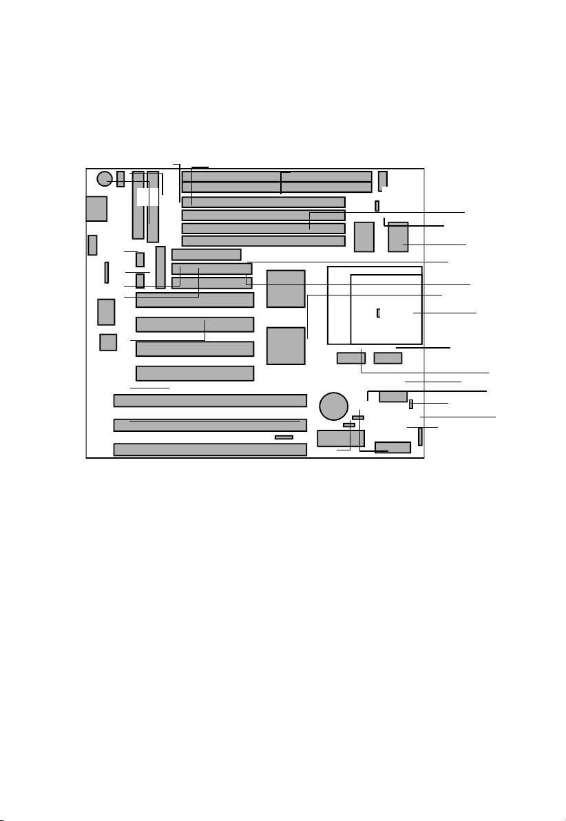
2.1 Motherboard ayout
A. 2x 168-pin DIMM sockets
B. A X Power Connector
C. A Power Connector
D. PS/2 Mouse
E. A Keyboard Connector
F. USB 2 Channel Ports
G. Rear IrDA X/RX
H. COM 1,2
I. Parallel Port
J. 4xPCI Bus Master Slots
K. 3xISA 16-bits Slots
L. External Battery Connector
M. 4x72-pin SIMM sockets
N. HCLK frequency select
DIP-switch
O. Cache Memory Pipeline
Burst SRAM
P. Floppy Connector
Q. PCI Bus Master IDE PIO
Mode 3,4 DMA Mode 2
R. Intel 430 X Chipsets
S. ZIF Socket 7 for CPU
. CPU ype Selector
U. Frequency Ratio Selector
V. CPUVCORE Jumper
W. Flash BIOS +12v/+5v
select
X. Fan Connector
Y. Front IrDA X/RX
Z. Front Panel Connector
AA. Clear CMOS Jumper
BB. Award/AMI BIOS with
BIOSGreen PC Features
EP-P 11 User's Manual
6
S
R
M
N
O
P
Q
U
V
Y
Z
AA
BB
D
F
G
I
H
J
K
L
W
X
BA
C
E

2. Installation
2.2 Installation Steps
1. Install SIMM (and DIMM) memory modules
2. Install the CPU
3. Install Expansion Card(s)
4. Install the External Connectors
5. Power On Procedures
6. Set jumpers for CPU type and speed.
EP-P 11 User's Manual
7
2. Installation
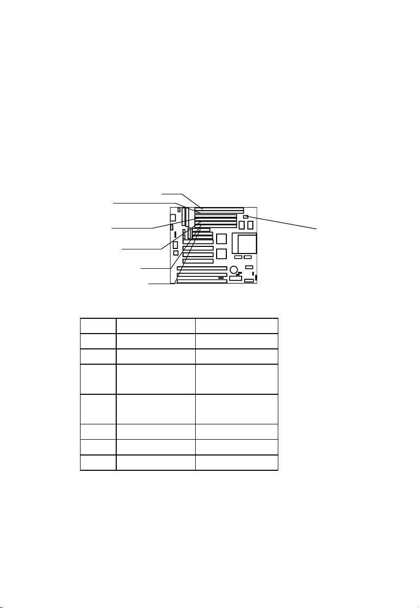
2.3 System Memory (SIMM and DIMM)
his motherboard supports four 72-pin SIMMs (Single Inline
Memory Modules) of 4MB, 8MB, 16MB, 32MB, and/or 64MB to
form a memory size between 8MB to 256MB. he DRAM can be
either 60ns or 70ns Fast Page Mode (FPM, Asymmetric or
Symmetric), Extended Data Output (EDO). SIMMs must be installed
in pairs so that each bank contains two of the same size memory
modules.
Install memory in any or all of the banks an any combination as
shown in the table below:
Item Bank Memory Module
1 DIMM 1 8-128MB
2 DIMM 1, 2 8-128MB
3 DIMM 2
SIMM 3, 4
8-128MB
4 DIMM 1
SIMM 1, 2
8-128MB
4-32MB
5 SIMM 1, 2 4-32MB
6 SIMM 3, 4 4-32MB
7 SIMM 1, 2, 3, 4 4-32MB
NOTE: You cannot mix two types (FPM, EDO, or SDRAM) or sizes
of memory in a single bank. After installing any memory modules,
setup is required using "Auto Configuration" in the Chipset Features
section of BIOS setup.
EP-P 11 User's Manual
8
SDRAM voltage
select (3.3v/5v)
DIMM 2
DIMM 1
SIMM 4
SIMM 1
SIMM 2
SIMM 3

2. Installation
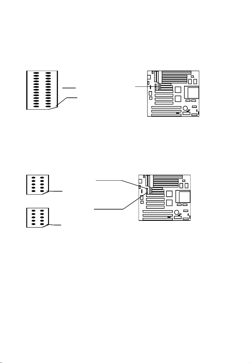
2.3.1 IMM/DIMM Memory Installation Procedures:
1. he SIMM memory modules will only fit in one orientation
because of a plastic Safety Tab on one end of the SIMM socket
which exactly fits the notched end of the SIMM module.
2. Press the SIMM into its socket at a 45-degree angle to the
motherboard, making sure that all the contacts are aligned with the
socket.
3. With you finger tips, gently push the memory module into a
vertical position so that it clicks into place.
4. he plastic guides should go through the two mounting holes on
the sides and the metal clips should snap on the other side.
5. o remove a memory module, squeeze both metal clips outwards
and rock the module back to a 45-degree angle, then lift it out of
the socket.
6. his motherboard is optimized for SDRAM performance: It
supports the new generation Synchronous Dynamic Random
Access Memory (SDRAM), and allows combined usage of SIMM
and DIMM memory modules.
2.4 Central Processing Unit (CPU)
he motherboard provides a 321-pin ZIF Socket 7. he CPU should
have a fan attached to it to prevent overheating. If the CPU did not
come with a fan then purchase a fan before you turn on your system.
Apply thermal jelly to the CPU top and then install the fan onto the
CPU.
NOTE: Without a fan, the CPU can overheat and cause damage to
both the CPU and the motherboard.
2.4.1 Installing the CPU
o install a CPU, locate the ZIF socket and open it by first pulling the
lever sideways away from the socket's "Lock" then upwards to a 90-
EP-P 11 User's Manual
9

2. Installation
degree angle. Insert the CPU with the correct orientation. he ZIF
socket has a square pattern of pinholes, but there is one hole missing
from the pattern in one corner. On the CPU, there is a white dot
printed near one corner, on the top face. Be sure that the white dot on
the CPU lines up with the odd corner of the socket. If you try to
insert the CPU in the wrong orientation, you could damage it!
You should have a CPU fan that will cover the face of the CPU. With
the added weight of the CPU fan, no force is required to insert the
CPU. Once completely inserted, hold down the fan and close the
socket's lever.
NOTE: You must set the CPU xternal Clock (BUS) Frequency
Selection and CPU to BUS Frequency Ratio according to the type of
CPU you install.
( ee chapter 3 CPU Settings for more information.)
2.4.2 Expansion Cards
Both ISA and PCI expansion cards may need an assigned IRQ.
System IRQs are available to cards installed in the ISA expansion bus
first, and any remaining IRQs are then used by PCI cards. Currently,
there are two types of ISA cards. he original ISA expansion card
design, now referred to as Legacy ISA, requires that you configure the
card's jumpers manually and then install it in any available slot on the
ISA bus. You may use Microsoft's Diagnostic (MSD.EXE) utility to
see a map of your used and free IRQs. For Windows 95 users, open
the "Control Panel" icon in "My Computer", and double-click on the
"System" icon, then click on the "Device Manager" tab. Double
clicking on a specific device gives you "Resource" tab which shows
the Interrupt number and address. Make sure that no two devices use
the same IRQs or your computer will experience problems when those
two devices are in use at the same time.
o simplify this process this motherboard has complied with the Plug
and Play (PnP) specification, which was developed to allow automatic
system configuration whenever a PnP-compliant card, is added to the
EP-P 11 User's Manual
10

2. Installation
system. For PnP cards, IRQs are assigned automatically from those
currently available.
If the system has both Legacy and PnP ISA card installed, IRQs are
assigned to PnP cards from those not used by Legacy cards. he PCI
and PnP Configuration section of the BIOS setup utility can be used
to indicate which IRQs are being used by Legacy cards. For older
Legacy cards that do not work with the BIOS, you can contact your
vendor for an ISA configuration utility. An IRQ number is
automatically assigned to PCI expansion cards after those used by
Legacy and PnP ISA cards. In the PCI bus design, the BIOS
automatically assigns an IRQ to any PCI slot which has a card that
requires an IRQ. o install a PCI card, you need to set something
called the IN (interrupt) assignment. Since all the PCI slots on this
motherboard use an IN A#, be sure that the jumpers on your PCI
cards are set to IN A.
2.4.2.1 Assigning DMA Channels for ISA Cards
Some ISA cards, both Legacy and PnP may also need to use a DMA
(Direct Memory Access) channel. DMA assignments for this
motherboard are handled the same way as the IRQ assignment process
described above. You can select a DMA channel in the PCI and PnP
configuration section of the BIOS Setup utility.
NOTE: Choose "Yes" for those IRQ's and DMA's you wish to
reserve for Legacy (Non-PnP) ISA expansion cards in "IRQ xx Used
by ISA" and "DMA x Used By ISA" under PnP and PCI Setup in the
BIOS Setup, otherwise conflicts may occur.
EP-P 11 User's Manual
11

2. Installation
2.5 External Connectors
NOTE: Please refer to the diagram on page 6 and to the markings on
the motherboard to be sure that connectors and jumper caps are placed
correctly. Placing jumper caps on connector pin-blocks can cause
damage to your motherboard.
2.5.1 Keyboard Connector and U B Port
(J16, 5-pin Female and J13, 8-pin Female)
USB Pinout:
1 USBV0
2 USBV1
3 USBD0-
4 USBD1-
5 USBD0+
6 USBD1+
7 USBG0
8 USBG1
2.5.2 P /2 Mouse Connector (J18)
If you are using a PS/2 mouse, you must enable the PS/2 port in the
BIOS Setup.
Pin 1 VCC
2 NC
3 NC
4 NC
5 MSDA
6 NC
7 GND
8 MSCLK
EP-P 11 User's Manual
12
USB Port
Pin #1
Keyboard Port
J18, PS/2
Mouse
Pin #1
2. Installation
2.5.3 Parallel Printer Port (CON2, 25-pin Female)
You can enable or disable the parallel port (LP 1) and choose its IRQ
number in the BIOS setup.
2.5.4 erial Ports (COM1, COM2, 9-pin Male Connector)
he two serial ports (COM1 & COM2) can be used for pointing
devices or other serial devices. See Onboard Serial Port in Chipset
Features Setup in the BIOS setup software to configure.
EP-P 11 User's Manual
13
COM2 Port
Pin #1
Pin #1
COM1 Port
Parallel Port ( ON2”)
Pin #1

2. Installation
2.5.5 AT & ATX Power upply Connectors
J14 is a standard 12-pin A -type or PS/2 type socket. Be sure to
attach the two connectors with the two black wires next to each other,
at the centre. J15 is a standard A X-type power connector. ( he
A X power connector can only be inserted the correct way.)
2.5.6 Floppy Drive Connector (J12, 34-pin block)
he motherboard provides a standard floppy disk (FDD) connector
that supports 360K, 720K, 1.2M, 1.44M and 2.88M floppy disk types.
You can attach a floppy disk cable directly to this connector.
2.5.7 Primary/ econdary IDE connectors. (J9 & J11: 40-pin
blocks)
hese connectors support the provided IDE hard disk ribbon cable.
After connecting the single end to the board, connect the plug(s) at the
EP-P 11 User's Manual
14
FDD Connector
Pin #1
Black Wires
at Center
A Power Connector
A X Power
Connector
Keyhold

2. Installation
other end to your hard disk drive(s). If you install two hard disks, you
must configure the second drive to slave mode by setting its jumper
accordingly. Please refer to your hard disk documentation for the
jumper settings. he BIOS now supports SCSI device or IDE CD-
ROM boot-up (see "Boot Sequence" in the BIOS Features Setup of
the BIOS Software)
2.5.8 Front Panel Connector
2.5.8.1 IDE Activit LED (J1, pins 2-4)
hese pins connect to the IDE (hard disk) activity indicator light on
the system cabinet.
2.5.8.2 S stem Power LED (J1, pins 9/11-13)
his connector accepts both 2-pin and 3-pin plugs. It lights the
system power LED when the motherboard has power.
EP-P 11 User's Manual
15
Primary IDE
Secondary IDE
Pin #1
Pin #1
J1
HDD LED
(pins 2-4)
Pin 2 (+)
Table of contents
Other ENPC Motherboard manuals


