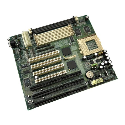
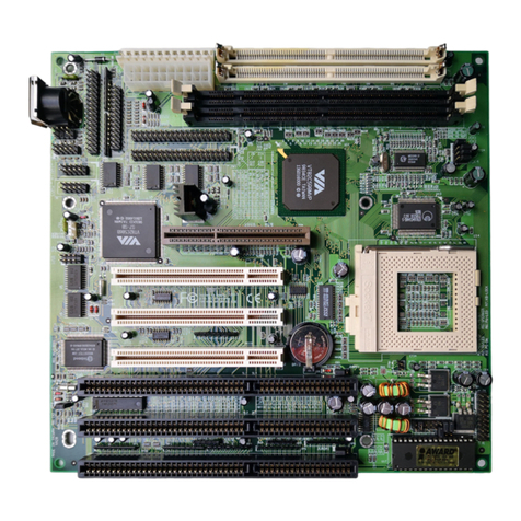
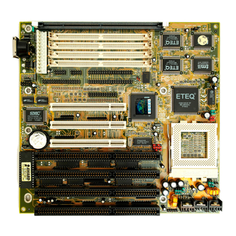
ENPC EP-PT21 User manual

EP-PT21
Motherboard for
Pentium MMX ™
User's Manual
Order Number 41010007
November, 1997

EC-CONFORMITY DECLARATION
(EC conformity marking)
FO THE FOLLOWING EQUIPMENT:
Product Name : MOTHE BOA D
Model: EP-PT21
Manufacturer: ENPC TECHNOLOGY CO P.
Manufacturer Address: 6FL., No. 19, Wu Chuan 6 d.,
Wu-Ku Industrial Park, Taipei, Taiwan.
IS HE EWITH CONFI MED TO COMPLY WITH THE EQUIPMENTS SET UP
IN THE COUNCIL DI ECTIVE ON THE APP OXIMATION OF THE LAW OF
MEMBE STATES ELATING TO ELECT OMAGNETIC COMPATIBILITY
(89/336/EEC) AND LOW VOLTAGE DI ECTIVE 78/28/EEC. FO THE
EVALUATION EGA DING THE ELECT OMAGNETIC COMPATIBILITY
AND SAFETY, THE FOLLOWING STANDA DS WE E APPLIED:
* EN50081-1 (1992) : GENE IC EMISSION STANDA DS
EN550022 (1994) : EMISSION
EN60555-2 (1987) : HA MONICS
EN60555-3 (1987) : VOLTAGE FLUCTUATIONS
* EN50082-1 (1992) : GENE IC IMMUNITY STANDA D
IEC 801-2 (1984) : ELECT OSTATIC DISCHA GE IMMUNITY
IEC 801-3 (1984) : ADIATED IMMUNITY
IEC 801-4 (1988) : ELECT ICAL FAST T ANSIENT
The manufacturer also declares the conformity of above mentioned product with the
actual required safety standards in accordance with LVD 73/23 EEC.
Manufacturer/Importer
Date: Nov 16, 1997
Signature: Signature:
Name: JEFF CHANG Name: KUNNAU CHEN
(Project Leader) (President)
EP-PT21 User’s Manual

EP-PT21
Motherboard
for
Compatible PC
User Manual ev 1.3
elated Motherboard: EP-PT21 P.C.B. ev 2.1
Date: Nov. 1997
EP-PT21 User’s Manual i

FCC & DOC COMPLIANCE
Federal Communication Commi ion Statement
This device complies with FCC ules Part 15. Operation is subject to the
following two conditions:
This device may not cause harmful interference, and
This device must accept any interference received, including
interference that may cause undesired operation.
This equipment has been tested and found to comply with the limits for a
Class B digital device, pursuant to Part 15 of the FCC ules. These limits
are designed to provide reasonable protection against harmful interference
in a residential installation. This equipment generates, uses and can radiate
radio frequency energy and, if not installed and used in accordance with
manufacturer's instructions, may cause harmful interference to radio
communications. However, there is no guarantee that interference will not
occur in a particular installation. If this equipment does cause harmful
interference to radio or television reception, which can be determined by
turning the equipment off and on, the user is encouraged to try to correct the
interference by one or more of the following measures:
e-orient or relocate the receiving antenna.
Increase the separation between the equipment and receiver.
Connect the equipment to an outlet on a circuit different from that to
which the receiver is connected.
Consult the dealer or an experienced radio/TV technician for help.
Warning: The use of shielded cables for connection of the monitor to the
graphics card is required to assure compliance with FCC regulations.
Changes or modifications to this unit not expressly approved by the party
responsible for compliance could void the user's authority to operate this
equipment.
Canadian Department of Communication Statement
This digital apparatus does not exceed the Class B limits for radio noise
emissions from digital apparatus set out the adio Interference egulations
for the Canadian Department of Communications.
EP-PT21 User’s Manual
ii

Table Of Content
1. INTRODUCTION.........................................................................................IV
1.1 ABOUT THIS MANUAL........................................................................IV
1.2 ITEM CHECKLIST.................................................................................V
1.3 SPECIFICATIONS...................................................................................1
1.4 NOTES ON INSTALLATION...................................................................1
2. INSTALLATION.............................................................................................1
2.1 MOTHE BOA D LAYOUT.....................................................................1
2.2 INSTALLATION STEPS...........................................................................2
2.3 SYSTEM MEMO Y................................................................................2
2.4 CENT AL P OCESSING UNIT (CPU)....................................................3
2.4.1 Installing the CPU.....................................................................3
2.4.2 Setting CPU Speed with ”Easy-Jumpers”.................................4
2.5 EXTE NAL CONNECTO S.....................................................................6
2. .1 PS/2 Keyboard Connector and USB Port.................................6
2. .2 Parallel Printer Port (CON2, 2 -pin Female)..........................6
2. .3 Serial Ports (COM1, COM2, 9-pin Male Connector)...............7
2. .4 AT & ATX Power Supply Connectors........................................7
2. . Floppy Drive Connector (J9, 34-pin block)..............................8
2. .6 Primary/Secondary IDE connectors. (J6 & J7: 40-pin blocks) 8
2. .7 IDE Activity LED (J22, pins 2-4)..............................................9
2. .8 Front Panel Connector..............................................................9
2. .9 CPU Cooling Fan Connector (J )..........................................12
2. .10 IrDA Connector (J21: Front IR; J10: Rear IR)....................13
2. .11 External Battery Connector (J1)...........................................13
2. .12 Clear CMOS Connector (J4).................................................14
EP-PT21 User’s Manual i

1. Introduction
1.1 About this Manual
This manual is arranged to help you set up and run this Pentium
MMX™ Motherboard as quickly as possible.
Information is presented in the following two chapters:
Chapter 1.
Introduction: This chapter presents the features of the motherboard;
what components and accessories should be included with it;
and describes the specifications of this product, including a
diagram of the motherboard layout.
Chapter 2.
Installation: This chapter shows how to install the motherboard, and
how to configure its various features and functions.
EP-PT21 User’s Manual
ii

1.2 Item Checklist
This product comes with the following components:
Motherboard x 1
40-pin IDE connector flat cable x 1
34-pin floppy disk drive flat cable x 1
User's manual x 1
Flash OM utility & Bus master IDE driver diskette (Optional)
ear panel shielding (Optional)
IrDA module (Optional)
EP-PT21 User’s Manual i

1.3 Specifications
Processor:
ZIF socket 7 support intel® Pentium MMX™; intel® P54C,
P55C Series, Cyrix 6x86/M2 Series, and AMD K5/K6 Series.
Supports current and future CPUs.
Chipset:
intel® 82430TX System Controller; intel® 82371AB PCI/ISA
IDE Accelerator.
BIOS:
Award/AMI BIOS support DMI; Flash OM with Green PC,
Plug-and-Play, ACPI, and PC97
System Memory:
Four 72-pin SIMMs and two 168-pin DIMM Slots support up
to 256MB. The system supports mixed memory technologies:
Extended Data Out (EDO) AM, Fast Page (FP) D AM, and
SD AM (Synchronous D AM).
On-board Multi-I/O:
1 x FDD Port supports up to 2.88MB
1 x Parallel Port (LPT) support ECP/EPP
2 x High Speed Serial (16550 UA T) Ports
2 x Universal Serial Bus (USB) Ports
1 x PS/2 Keyboard Port
1 x PS/2 Mouse Port
1 x eal Time Clock ( TC)
2 x IrDA ports
Cache Onboard:
512KB Pipeline Burst S AM Cache
EP-PT21 User’s Manual i

PCI Bus Master IDE:
2 x PCI Bus Master IDE Controllers
Support PIO Mode 3/4 EIDE Devices (HDD, CD- OM, LS-
120 FDD, etc.);
Ultra DMA/33 mode; and HDD Auto-Detect
Expansion Slots:
4 x 32-bit PCI Bus Master Slots, 3 x 16-bit ISA Slots
Options:
Infrared (IrDA) Wireless Interface Kit
LM75 CPU Temperature Gauge
LM78 Hardware Monitor Chip
Dimensions:
210mm x 305mm
Form Factor:
ATX Form Factor
EP-PT21 User’s Manual i

1.4 Notes On Installation
This motherboard has been designed with the Intel 82430TX, PCI
chipset, which was developed by Intel Corporation to fully support
the Pentium Processor PCI/ISA system. The Intel 82430TX PCI
chipset provides increased integration and improved performance.
The chipset provides an integrated IDE controller with two high
performance IDE interfaces, for up to four IDE devices (hard devices,
CD- OM device, etc). The Super I/O controller provides standard
I/O functions: floppy interface, two serial ports with 16-Byte FIFO
buffers, and an EPP/ECP-capable parallel port.
Care must be taken when inserting memory modules, inserting the
CPU, or even plugging PCI cards into associated slots to avoid
damaging any circuits or sockets on the motherboard. A cooling fan
is strongly recommended when installing P54C, P54CTB, P55C, K5,
K6, 6x86, or M2 CPU, to avoid overheating.
The motherboard requires a minimum of 8MB of system memory,
and can support a maximum of 256MB.
The onboard L2 Cache comprises 256KB or 512KB of static AM
(S AM) to increase system performance.
The motherboard supports standard Fast Page (FP), EDO (Extended
Data Out), or SD AM (Synchronous D AM) memory, and provides
four 72-pin SIMMs and two 168-pin DIMMs. The sockets support
1Mx32(32MB) single-sided or double-sided memory modules.
Memory timing requires 70ns Fast Page devices or 60ns EDO AM.
Memory parity generation and checking is not supported. (D AM
Modules may be parity (x36) or non-parity (x32).
The board also has two onboard PCI IDE connectors, and detects the
IDE hard disk type through an automatic BIOS utility. The system
also supports Award Plug & Play BIOS for the ISA and PCI cards.
EP-PT21 User’s Manual i

2. Installation
2. Installation
2.1 Motherboard ayout
EP-PT21 User’s Manual i
Program Connector
Intel 430TX Chipset
CPU type select
Intel 430TX Chipset
512KB Cache
CPU speed select
LM75 CPU temp. sensor
ZIF CPU socket
Switching voltage regulator
Two 168-pin
DIMM sockets
Four 72-pin SIMM
sockets
ear IrDA port
COM1 serial port
Parallel port
COM2 serial port
PS/2 Keybd/Mouse
AT power connector
ATX power connector
USB serial port
Front panel jumper
Clear CMOS jumper
DIMM
voltage select
FDD Connector
Primary IDE
Secondary IDE
Three ISA slots
External battery
connector
LM78 hardware
monitor
Super I/O chipset
Lithium battery
Super I/O Chipset
Four PCI slots
Fan connector
Front IrDA port
Award BIOS

2. Installation
2.2 Installation Steps
1. Set jumpers on the motherboard
2. Install D AM (and SD AM) memory modules
3. Install the CPU
4. Install Expansion Card(s)
5. Install the External Connectors
2.3 System Memory
This motherboard supports four 72-pin SIMMs (Single Inline
Memory Modules) of 4MB, 8MB, 16MB, 32MB, and/or 64MB to
form a memory size between 8MB to 256MB. The D AM can be
either 60ns or 70ns Fast Page Mode (FPM, Asymmetric or
Symmetric), Extended Data Output (EDO). SIMMs must be installed
in pairs so that each bank contains two of the same size memory
modules.
Install memory in any or all of the banks at any combination as shown
in the table below:
EP-PT21 User’s Manual
2
SD AM voltage
select (3.3v/5v)
SIMM 4
SIMM 3
SIMM 2
DIMM 1
DIMM 2
SIMM 1

2. Installation
Item Bank Memory Module
1 DIMM 1 8-128MB
2 DIMM 1, 2 8-128MB
3 DIMM 2
SIMM 3, 4
8-128MB
4-64MB
4 DIMM 1
SIMM 1, 2
8-128MB
4-64MB
5 SIMM 1, 2 4-64MB
6 SIMM 3, 4 4-64MB
7 SIMM 1, 2, 3, 4 4-64MB
NOTE: You cannot mix two types (FPM, EDO, or SD AM) or sizes
of memory in a single bank. After installing any memory modules,
setup is required using "Auto Configuration" in the Chipset Features
section of BIOS setup.
2.4 Central Processing Unit (CPU)
The motherboard provides a 321-pin ZIF Socket 7. The CPU should
have a fan attached to it to prevent overheating. If the CPU did not
come with a fan then purchase a fan before you turn on your system.
Apply thermal jelly to the CPU top and then install the fan onto the
CPU.
NOTE: Without a fan, the CPU can overheat and cause damage to
both the CPU and the motherboard
2.4.1 In talling the CPU
To install a CPU, locate the ZIF socket and open it by first pulling the
lever sideways away from the socket's "Lock" then upwards to a 90-
degree angle. Insert the CPU with the correct orientation as shown.
Look to see that the pins are denser on one half compared to the other
half. You should have a CPU fan that will cover the face of the CPU.
With the added weight of the CPU fan, no force is required to insert
EP-PT21 User’s Manual i

2. Installation
the CPU. Once completely inserted, hold down the fan and close the
socket's lever.
2.4.2 Setting CPU Speed with ”Ea y-Jumper ”
The Easy-Jumpers system greatly simplifies the task of setting the
proper CPU type and speed. All the information you need is clearly
marked right on the motherboard.
First, set the CPU type (P54C, MMX, K5, ... etc.) with one jumper
cap on the J25 pin block.
Next, set the bus speed. The default value (with no jumpers added) is
66Mhz. If you need to use 75MHz or 83.3MHz, then place a jumper
cap over the appropriate pins on block J24. Pins 17-18 set 75MHz;
and pins 19-20 set 83.3MHz.
Finally, set the CPU speed as a multiple of the bus speed on J24.
Note that there are two captions next to each pair of pins in J24. The
first one is a multiplication factor, such as 2.0”; and the second is a
CPU speed based on the default bus speed of 66MHz.
Thus, if you set a bus speed other than the default, you should pay
attention only to the multiplication factor and NOT the pre-printed
CPU speeds.
For example, suppose you have a Pentium-150 CPU, and you wish to
run with a bus speed of 75MHz. You would place three jumper caps,
as follows:
EP-PT21 User’s Manual
1.5
2.0
2.5
3.0
3.5
4.0
4.5
5.0
4
J25, CPU Type
J24, Clock
Speed

2. Installation
J25, pins 1-2 (P54C) J24, pins 21-22 (X75)
pins 3-4 (x2.0)
1
3
3
1
6
6
2
0
0
2
3
3
2
6
6
3
0
0
3
3
0
1
0
0
X
8
3
.
3
X
7
5
This would give you a bus speed of 75MHz, and a CPU speed of
150MHz.
Note: although the caption next to the jumper in this example reads
x2.0 | 133, the actual speed is 75MHz X 2.0, or 150MHz.
EP-PT21 User’s Manual i
Sets CPU type to P54C
Selects 75MHz bus
Sets CPU speed to
2.0X bus speed

2. Installation
2.5 External Connectors
NOTE: Please refer to the diagram on page 1 and to the markings on
the motherboard to be sure that connectors and jumper caps are placed
correctly. Placing jumper caps on connector pin-blocks can cause
damage to your motherboard.
2.5.1 PS/2 Keyboard/Mou e Connector and USB Port
(J17, 2x 6-pin Female and J16, 6-pin Female)
2.5.2 Parallel Printer Port (J14, 25-pin Female)
You can enable or disable the parallel port (LPT1) and choose its I Q
number in the BIOS setup.
2.5.3
EP-PT21 User’s Manual
6
J16 : USB Connector
J17 : Keyboard/Mouse Connector
J14 : Parallel
Port
(Support Standard
USB Specification)

2. Installation
2.5.4 Serial Port (COM1, COM2, 9-pin Male Connector)
The two serial ports (COM1 & COM2) can be used for pointing
devices or other serial devices. See Onboard Serial Port in Chipset
Features Setup in the BIOS setup software to configure.
2.5.5 AT & ATX Power Supply Connector
J23 is a standard 12-pin AT-type or PS/2 type socket. Be sure to
attach the two connectors with the four black wires next to each other,
at the centre. J12 is a standard ATX-type power connector. (The
ATX power connector can only be inserted the correct way.)
EP-PT21 User’s Manual i
COM1 Port
J23 :
AT Power
Connector
J12 :
ATX Power
Connector
Keyhold
COM2 Port
Black Wires
at Center
J11 :
J15 :

2. Installation
2.5.6 Floppy Drive Connector (J9, 34-pin block)
The motherboard provides a standard floppy disk driver (FDD)
connector that supports 360K, 720K, 1.2M, 1.44M and 2.88M floppy
disk types. You can attach a floppy disk cable directly to this
connector.
2.5.7 Primary/Secondary IDE connector . (J6 & J7: 40-pin
block )
These connectors support the provided IDE hard disk ribbon cable.
After connecting the single end to the board, connect the plug(s) at the
other end to your hard disk drive(s). If you install two hard disks, you
must configure the second drive to slave mode by setting its jumper
accordingly. Please refer to your hard disk documentation for the
jumper settings. The BIOS now supports SCSI device or IDE CD-
OM boot-up (see "Boot Sequence" in the BIOS Features Setup of
the BIOS Software)
EP-PT21 User’s Manual
8
Secondary
IDE
Primary
IDE
FDD Connector
Pin #1
Primary IDE
Secondary IDE
Pin #1 Pin #1

2. Installation
2.5.8
EP-PT21 User’s Manual i

2. Installation
2.5.9 IDE Activity LED (J22, pin 2-4)
These pins connect to the IDE (hard disk) activity indicator light on
the system cabinet.
2.5.10 Front Panel Connector
2.5.10.1 System Power LED (J22, pins 9/11-1 )
This 2-pin connector lights the system power LED when the
motherboard has power
EP-PT21 User’s Manual
10
J22
J22
HDD LED
(pins 2-4)
pins 11-13, for
2-pin connector
pins 9-13, for
3-pin connector
Table of contents
Other ENPC Motherboard manuals
