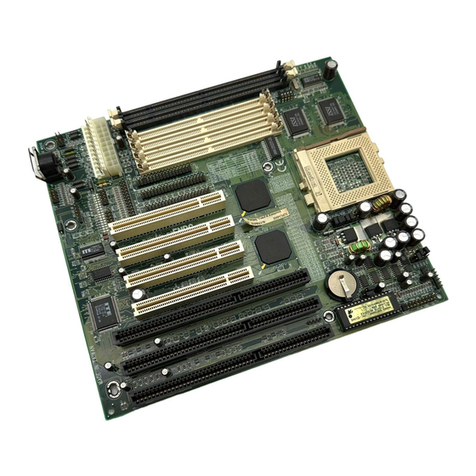
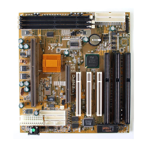
ENPC EP-PI11 User manual

EP-PI11
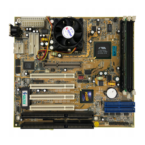
Motherboard of
Pentium with MMX
User’s Manual
Order Number 41010012
January 1998
User Manual Rev 1.0
Related Motherboard: EP-PI11 P.C.B. Rev 1.X
Date: Jan. 199

i
Chapter 1 INTRODUCTION
T BLE OF CONTENTS
Chapter 1.............................................................................................1
1-1 About this Manual……..................................................................1
1-2 Item Checklist…………................................................................2
1-3 Specifications………….................................................................3
Chapter 2.............................................................................................5
2-1 Motherboard Description...............................................................5
2-2 Motherboard Layout……..............................................................6
2-3 System Memories……….........................................................…..7
2-4 Central Processing Unit (CPU)......................................................9
2-5 Expansion Cards & Slots..............................................................10
2-6 External Connectors…….............................................................11
2-7 Hardware Jumper/Switch Setup...................................................23
PEENDIX What is the AGP (Accelerated Graphics Port ) ?...............29
PEENDIX B FCC & DOC Declation Of Conformity.......................30
PEENDIX C CE Declation Of Conformity......................................31
EP-PI11 User’s Manual

11
Chapter 1 INTRODUCTION
1-1 bout this Manual
This manual is arranged to help you set up and run this Motherboard
of Pentium with MMX as soon as possible.
The information is presented in the following two chapters:
Chapter 1 Introduction:
Presents what you should receive with your
motherboard, the features and specifications
of the product. This chapter enclosed with a
diagram showing the layout of the
motherboard.
Chapter 2 Installation:
Motherboard Installation includes detailed
information on how to install and configure
the motherboard.
EP-PI11 User’s Manual

2
Chapter 1 INTRODUCTION
1-2 Item Checklist
This product comes with the following components:
Motherboard x 1
40-pin IDE Connector Flat Cable x 1
34-pin Floppy Disk Drive Flat Cable x 1
Bracket with 25-pin serial port and PS/2 Mouse ribbon cable x 1
User’s Manual x 1
Bracket with Com Port and Printer Port Flat cable x 1
Bus Master IDE/Ultra DMA-33 Drivers Diskette x 1 (Option)
IrDA Module x 1 (Option)
LDCM Diskette x 1 (Option)
USB Connector Cable with bracket x 1 (Option)
Option : Components will be included upon
customer ordering instructions per
Proforma Invoice & additional external
procurement cost will be included.
EP-PI11 User’s Manual

11
Chapter 1 INTRODUCTION
1-3 Specifications
Processor: ZIF socket 7 support intel® Pentium
MMX™; intel® P54C, P55C Series,
Cyrix 6x 6/M2 Series, and AMD K5/K6
Series. Supports current and future CPUs.
(Cyrix 6x86 linear burst support)
Chipset: VIA VT 2C59 AT North Bridge for Pentium
VIA VT 2C5 6B South Bridge with ACPI
Power Management
BIOS: Award BIOS With Flash ROM, support PnP,
PCI 2.1, CD-ROM, ATAPI, LS-120, and any
IDE Device Bootable, Virus Protection, DMI
Ready
System Memory: Two 72-pin SIMMs
and two 16 -pin DIMM Slots supports.
The system supports mixed memory
technologies: Extended Data Out (EDO)
RAM, Fast Page (FP) DRAM, and
SDRAM (Synchronous DRAM)
Multi-I/O Onboard:
1 x FDD Port support up to 2. MB
1 x Parallel Port (LPT) support ECP/EPP
2 x High Speed Serial (16C550 UART) Ports
2 x Universal Serial Bus (USB) Ports
1 x AT Keyboard Port
1 x PS/2 Mouse Port
1 x IrDA Infrared Interfaces
EP-PI11 User’s Manual

4
Chapter 1 INTRODUCTION
PCI Bus Master IDE: PCI Enhanced IDE Interface with 4 IDE
Devices
Support HDD Auto-Detect
Support up to PIO Mode 4, DMA Mode 2
Support UltraDMA-33 extensions
Support ATAPI compliant device include
DVD devices
Fully compatible with PCI Local Bus
Specifications V2.1
I/O Connector: 2 x USB Ports, 1 x AT Keyboard Port,
1 x PS/2 Mouse Port, 1 x Parallel Port,
2 x Serial Port
Expansion Slots: 3 x 16-bit ISA Slots with 100% ISA
Compatible Functions
3 x 32-bit PCI Slots supporting PCI BUS
Master Slots Conform with PCI
Specifications Version 2.1
1 x AGP Slot supported.
Options: 1 x Infrared (IrDA) Wireless Interface Kit
1 x Universal Serial Bus (USB) Connector
Kit
Extended Features: Advanced Configuration and Power
Interface (ACPI) ready
Support Win95 Soft-Off (For ATX Power
only)
Support “Programmable OnNow / Security
Wake-Up” feature
Support SM-Bus
Dimension: 220 mm x 230 mm
Form Factor: Baby AT Form Factor
EP-PI11 User’s Manual

11
Chapter 2 INST LL TION
2-1 Motherboard Description
The motherboard is designed with the VIA VT 2C597AT PCI chipset
which is developed by VIA Corporation to fully support the
Pentium Processor PCI/ISA system. The VIA VT 2C597AT PCI
chipset provides increased integration and improved performance
designs. The chipset provides an integrated IDE controller with two
high performance IDE interfaces for up to four IDE devices (hard
devices, CD-ROM device, etc). The Super I/O controller provides the
standard PC I/O function: floppy interface, two 16-Byte FIFO serial
ports and EPP/ECP capable parallel port.
Care must be taken when inserting memory modules, inserting CPU
or even plugging PCI card into associated slots to avoid damaging any
circuits or sockets on board. A cooling fan is strongly recommended.
The motherboard supports minimum of MB of system memory and a
maximum 1GB RAM.
The motherboard supports standard Fast Page (FP), EDO (Extended
Data Output), or SDRAM (Synchronous DRAM). The motherboard
provides two 16 -pin DIMM.
The board also supports onboard two PCI IDE connectors, and detects
the IDE hard disk type by the BIOS utility which is automatic. The
system also supports Award Plug & Play BIOS for the ISA and PCI
cards.
EP-PI11 User’s Manual

6
Chapter 2 INST LL TION
2.2 Motherboard Layout
EP-PI11 User’s Manual
Modem/LAN
Wake Up
ISA
USB
Connector
HCLK
Select
DIMM2
DIMM1
SIMM2
SIMM1
ATX Power Conn.
AT Power Conn.
LPT
Front
Panel
Connector
BIOS
Flash ROM
VPP Select
COMS
Clear
Connector
K/B
Power On
Select
AT
Keyboard
IDE2
IDE1
COM1
COM2
Rear
IrDA
PS/2
Mouse
AGP
CPU
Vcore
Selector
CPU
PCI
Fan
CO
nne
ctor
Freq
Ratio
Select
FDD

11
Chapter 2 INST LL TION
2-3 System Memories
This motherboard supports two 72-pin Single Inline Memory
Modules (SIMM) of 4MB, MB, 16MB, 32MB, and/or 64MB to
form a memory size between MB to 256MB. The DRAM can be
either 60ns or 70ns Fast Page Mode (FPM, Asymmetric or
Symmetric), Extended Data Output (EDO). SIMMs must be installed
in pairs so that each bank contains two of the same size and same
model memory modules.
This motherboard also supports two Dual Inline Memory
Modules (DIMM’S), The Dual Inline Memory Module (DIMM) must
be 3.3 Volt Unbuffered Synchronous DRAM (SDRAM) or Exteded
Data Output (EDO) DRAM of either 16, 32, 64, or 12 MB to form a
memory size between 16MB to 256MB.
Note :
1. Install memory in any combination as next page :
2. Do not mixed use SIMM and DIMM
EP-PI11 User’s Manual

Chapter 2 INST LL TION
Item Bank Memory Module
1 DIMM 1 16~12 MB
2 DIMM 1, 2 16~12 MB
3 DIMM 1, 2
SIMM 1, 2
16~12 MB
~64 MB
EP-PI11 User’s Manual
DIMM 1
DIMM 2
SIMM 1,
2
DIMM 1

11
Chapter 2 INST LL TION
2-4 Central Processing Unit (CPU)
The motherboard provides a Socket 7 for Pentium CPU. The CPU
should have a fan attached to it to prevent overheating. If your CPU
did not come with a fan, then purchase a fan before you turn on your
system.
To install a CPU, locate the Socket 7 (U14). Insert the CPU with the
correct orientation. you should have a CPU fan that will cover the face
of the CPU.
NOTE: Without a fan, the CPU can overheat and
cause damage to both the CPU and the
motherboard.
EP-PI11 User’s Manual
Socket 7
JCK1~3 : (Use pin header )
CPU Bus Clock Select

10
Chapter 2 INST LL TION
2-5 Expansion Cards & Slots
Assigning DMA Channels for ISA Cards:
Some ISA cards, both Legacy and PnP may also need to use a DMA
(Direct Memory Access) channel. DMA assignments for this
motherboard are handled the same way as the IRQ assignment process
. You can select a DMA channel in the PCI and PnP configuration
section of the BIOS Setup utility.
NOTE: 1, Choose “Legacy ISA” for those IRQ’s and
DMA’s you wish to reserve for Legacy
(Non-PnP) ISA expansion cards in “IRQ xx
Used by ISA” and “DMA x Used By ISA”
of the PnP and PCI Setup in the BIOS
Software section, otherwise conflicts may
occur.
This motherboard provide an AGP (Accelerated Graphics Port)
slot to support a new generation of graphics cards with ultra-high
memory bandwidth. (Note : For the detail of AGP to see appendix)
EP-PI11 User’s Manual
3 x PCI SLOTS
3 x ISA SLOTS
1 x AGP SLOT

11
Chapter 2 INST LL TION
2-6 External Connectors
1. Keyboard Connector and USB Port (CN1, 5-pin female
connector and JUSB, 10-pin Pin header)
This K/B connection is for a standard AT Keyboard connector
This USB connector will use USB connector kit. You may order
from your distribute.
2. PS/2 Mouse Connector (J4, 6-pin Pin header )
If you are using a PS/2 mouse, you must enable the PS/2 port in
the BIOS Setup.
Pin 1 VCC
2 NC
3 NC
4 (BLANK)
5 MSDAT
6 (BLANK)
7 GND
MSCLK
EP-PI11 User’s Manual
Note : The USB Port Support Standard USB Spec.
USB Pinout
1 USBV0
2 USBV1
3 USBD0-
4 USBD1-
5 USBD0+
6 USBD1+
7 USBG0
USBG1
PS/2 Mouse
Connector
K/B: Keyboard
Port
USB Port

12
Chapter 2 INST LL TION
3. Parallel Port (LPT, 26-pin Pin header)
You can enable the parallel port (LPT1) and choose the IRQ
through BIOS Setup on Onboard Parallel Port.
4. Serial Ports (COM1, COM2, 10-pin Pin header).
The two serial (COM1 & COM2) ports can be used for
pointing devices or other serial devices. See “Onboard Serial
Port” in Chipset Features Setup of the BIOS Software.
EP-PI11 User’s Manual
COM1 Port
Pin #1
Pin #1
COM2 Port
Pin #2
Pin #2
Parallel Port
Pin #1
Pin #2

11
Chapter 2 INST LL TION
5. AT & ATX Power Supply Connectors
CN3 is a standard 12-pin AT-type or PS/2 type connector. Be
sure to attach the two connectors with the two black wires
next to each other, at the center. CN4 is a standard ATX-type
power connector. (The ATX power connector can only be
inserted the correct way.)
NOTE:
To prevent electrical spikes, make sure that the power
supply is not connected to an outlet when making or removing
connections. Power supplies contain power reserves which
can damage electrical components.
EP-PI11 User’s Manual
Black Wires
at Center 4 wires
Key holder
ATX Power
Connector
AT Power Connector

Chapter 2 INST LL TION
6. Floppy Drive Connector (FDD, 34-pin Pin header)
This connector supports the provided floppy disk drive ribbon
cable. After connecting the single end to the board, connect the
plugs on the other end to one or two floppy drives. The
motherboard provides a standard floppy disk (FDD) connector
that supports 360K, 720K, 1.2M, 1.44M and 2. M floppy disk
types. You can attach a floppy disk cable directly to this
connector.
EP-PI11 User’s Manual
14
1
FDD
Connector

15
Chapter 2 INST LL TION
7. Primary/Secondary IDE connectors (IDE1 & IDE2: Two 40-
pin Pin header)
These connectors support the provided IDE hard disk ribbon
cable. After connecting the single end to the board, connect the
two plugs at the other end to your hard disk(s). If you install two
hard disks, you must configure the second drive to Slave mode by
setting its jumper accordingly. Please refer to the documentation
of your hard disk for the jumper settings.
EP-PI11 User’s Manual
IDE 2 : Secondary
HDD
IDE 1 : Primary
HDD
1
1

Chapter 2 INST LL TION
8. a. IDE ctivity LED (JP4, Pin 2, 4 )
This connector connects to the IDE (hard disk) activity
indicator light on the system cabinet.
EP-PI11 User’s Manual
16
1
Pin 2,4 : HDD
LED
Pin 2 (+)
(A1 Location)

17
Chapter 2 INST LL TION
b. System Power LED (JP4, Pin 9, 11, 13)
This 3-pin connector lights the system power LED when the
motherboard has power.
c. Turbo LED (JP4, Pin 6, )
EP-PI11 User’s Manual
2
2
1
For 3-pin Power LED Connector
JP4, Pin 9, 11, 13: System Power LED
If the cabinet provide the turbo LED cable,
connect the cable to this two pin connector to
turn on the LED on the front panel.
1
(A6 Location)
(A2 Location)

Chapter 2 INST LL TION
d. CMOS Clear Connector ( JVBAT1 )
The CMOS RAM is powered by the onboard button cell
battery.
You can following process to clear the RTC data :
(a) Turn-off power of computer
(b) To put the pin cap locate at “Clear” for a while
(c) Reput the pin cap locate at “Normal”, and turn-on
computer power
(d) Hold down <Del> key during the system booting and
enter BIOS setup screen to re-keyin the users setting.
EP-PI11 User’s Manual
1
Clear : Pin 2,3
Normal : Pin 1,2 (Default)
1
ClearNormal
Table of contents
Other ENPC Motherboard manuals
