ENPC EP-PS21 User manual

1
User’ s Manual Rev. A
CONTENTS
Item Checklist
Please check that your package is complete. If you discover damaged or
missing items, please contact your retailer.
Motherboard x 1
40-pin IDE Connector Flat Cable x 1
34-pin Floppy Disk Drive Flat Cable x 1
User’ s Manual x 1
CD x 1
LDCM Diskette x 1 (Option)
USB Connector Cable with bracket x 1 (Option)
IrDA Module x 1(Option)
Option : Components will be include upon customer ordering instructions
per Proforma Invoice & additional external procurement cost will be
included.
1. Specification .................................................................2
2. Chipset on this Mother Board........................................... 4
3. Parts Of The Mother Board ............................................ 6
4. MotherBoardLayoutQuick View ...................................... 7
5. Installation ................................................................ 8
5-1 Jumper Setting I 8
5-2 Jumper Setting II 9
5-3 Install System Memory Modules 11
5-4 Install the Central Processing Unit (CPU) 12
5-5 External Conncetion 13
5-6 Power On Procedure 21
Attached: BIOSSetup Tips.................................................. 22

2
User’ s Manual Rev. A
1. Specifications
Microprocessor
Support Intel P54C/P55C, AMD K5/K6/K6-2, Cyrix M1/M2 and other
Pentium compatible CPUs. The Front Side Bus Supports 66/75/83/
95/100/112 MHz host bus clock, selectable by jumpers.
ZIF Socket 7 for CPU Insert.
Cache and System Memory
512KB pipeline burst synchronous SRAM
Three 168 pin dual in line memory module (DIMM) sockets
Support up to 768 MB of synchronous DRAM (SDRAM)
Chipset (SiS 530/5595 PCI AGP/VGA chip set)
SiS 530 PCI/AGP VGA controller
Integrated AGP VGA for hardware 2D/3D video/graphics
accelerators
Integrated PCI bus mastering controller
Integrated second level cache controller
SiS 5595 PCI system I/O controller
Multifunction PCI-to-ISA bridge
Universal Serial Bus (USB) and DMA controllers
Two fast IDE interfaces that support up to four IDE drives or devices
Power management logic
Real-time clock
Video/Graphics Subsystems
Integrated high performance & high quality AGP 2D/3D accelerator
Programmable 2MB, 4MB, and 8MB shared frame buffer
Optional 4MB, and 8MB local frame buffer (manufacturing option)
24bit true colorRAMDACupto230MHz pixel clock,supports1024*7688/16/
32 bpp @85Hz NI
DVD hardware accelerator

3
User’ s Manual Rev. A
Audio Subsystems
ESS solo1 PCI 3D single chip audio controller
Mic-in, Line-out, Line-out, MIDI/Game port
I/O features
1 x FDD Port support up to 2.88MB
1 x Parallel Port (LPT) support ECP/EPP
2 x High Speed Serial (16C550 UART) Ports
2 x IDE Ports support Ultra DMA/33
2 x Universal Serial Bus (USB) Ports
1 x PS/2 Keyboard Port
1 x PS/2 Mouse Port
1 x IrDA Port
1 x VGA Port
Expansion slots
2 x 16-bit ISA Slots
3 x 32-bit PCI Slots
Other features
Award BIOS
Plug and Play compatible
Advanced Power Management (APM) 1.2 support
Advanced Configuration and Power Interface (ACPI) 1.0 support
Form factor
Micro ATX, 240mmX220mm

4
User’ s Manual Rev. A
2. Chipset on this Mother Board
The Motherbaoard use the Chipset of SiS530 & SIS5595 where SIS 530 is
fuinction for Host, PCI, 3D A.G.P. Video/Graphics & Memory Controller
and the SiS5595 is function for PCI SYSTEM I/O.
The SiS530/5595 chipset, provides a high performance/cost index Desk-
top/Mobile solution for the Intel Pentium P54C/P55C, AMD K5/K6/K6-II,
Cyrix M1/M2 and other compatible Pentium CPU with 3D A.G.P. VGA
system.
The Host, PCI, 3D A.G.P. Video/Graphics & Memory Controller, SiS530
integrates the Host-to-PCI bridge, the PCI interface, the L2 cache control-
ler, the DRAM controller, the high performance hardware 2D/3D VGA con-
troller, and the PCI IDE controller.
TheHostinterfacesupportsSynchronous/AsynchronousHost/DRAMclock-
ingconfiguration to eminently improvethesystemperformanceandDRAM
compatibilityissues.
The L2 cache controller can support up to 512 KB P.B. SRAM, and the
DRAM controller can support SDRAM memory up to 768 MBytes.
The built-in fast PCI IDE controller supports the ATA PIO/DMA, and the
Ultra DMA33 function that support the data transfer rate up to 33 MB/s. It
provides the separate data path for two IDE channels that can eminently
improve the performance under the multi-tasking environment.
The A.G.P. internal interface is supported for integrated H/W 3D VGA con-
troller. The integratedVGAcontrollerisa high performance andtargetedat
3Dgraphicsapplication. In addition, theintegrated3DVideo/Graphicscon-
troller adopts the 64bits 100MHz host bus interface high technology to im-
provetheperformanceeminently.Tocost-effectivethePCsystem,theshare
system memory architecture will be adopted and it can flexibly using the
2MB,4MBand 8MB framebuffersize from programmingthe system BIOS.
To enhance thesystem performance, SiS530also supports the localframe
buffer solution and memory sizes can support up to 8MB with SDRAM.

5
User’ s Manual Rev. A
As for DVD solution, the integrated 3D VGA controller also support DVD H/W
accelerator to improve the DVD playback performance.
TheSiS5595PCI system I/Ointegratesthe PCI-to-ISA bridgewiththe DDMA,
PC/PCI DMA and Serial IRQ capability, the ACPI/Legacy PMU, the Data Ac-
quisition Interface, the Universal Serial Bus host/hub interface, and the ISA
bus interface which contains the ISA bus controller, the DMA controllers, the
interrupt controllers, the Timers and the Real Time Clock (RTC). It also inte-
grates the Keyboard Controller and PS/2 mouse interface that can support
keyboard power on function for users to power on system by entering the hot
key or password from keyboard.
The built-in USB controller, which is fully compliant to OHCI (Open Host Con-
troller Interface), provides two USB ports capable of running full/low speed
USB devices.
The Data Acquisition Interface offers the ability of monitoring and reporting
the environmental condition of the PC. It could monitor 5 positive analog volt-
age inputs, 2 Fan speed inputs, and one temperature input.
In addition, SiS5595 also supports ACPI function to meet Advanced Configu-
ration and Power Interface (ACPI) 1.0 specification for Windows 98 environ-
ment,it can support power-managementtimer,Powerbutton, Real-time clock
alarmwakeup,more sleeping state, ACPILEDforsleeping and working state,
LAN wake up, Modem Ring In wake up, and OnNow initiative function.

6
User’ s Manual Rev. A
3. Parts Of The Mother Board
KeyBoard
Mouse
USB 1
USB 2 COM Port VGA Out OUT
IN MIC IN
Printer Port MIDI/GAME Port

7
User’ s Manual Rev. A
4. MotherBoard Layout Quick View
Special Connector description
J1: L2 Cache Linear Mode or Toggle Mode Selection
J2: CD-IN Connector ( L, G, G, R )
J3: CD-IN Connector ( G, L, G, R )
J4: Wake On LAN Connector
JP1: Select the CPU VIO 3.3V Power Source
JP2: CPU Frequency Ratio Setting
JP3: CPU VID Voltage Setting
JP4: CPU Front Side Bus setting
JP5: CPU VIO Voltage setting ( When JP1 set to DISABLE )
JP7: CMOS Clear
I
S
A
S
L
O
T
2
I
S
A
S
L
O
T
1
123
Socket 7
P
C
I
3
P
C
I
2
P
C
I
1
B
I
O
SIDE 2
IDE 1
DIMM
Sound / GAME / MIDI / USB /
VGA / COM / KB / Mouse Po
r
COM2
J2J3
CD IN (J2,J3)
JP7:
CMOS Clear
JP1
JP4 ATX Power
TAG
SYS FANCPU FAN
L2 Cache
SIS 530
SIS
5595
FDD
Video RAM
(Option)
Front Panel
ESS
1938
J4: WOL
IR Battery
JP5
J1
JP3 JP2
8
User’ s Manual Rev. A
5-1 Jumper Setting I
I
S
A
S
L
O
T
2
I
S
A
S
L
O
T
1
123
Socket 7
P
C
I
3
P
C
I
2
P
C
I
1
B
I
O
SIDE 2
IDE 1
DIMM
Sound / GAME / MIDI / USB /
VGA / COM / KB / Mouse Po
r
COM2
J2J3
CD IN (J2,J3)
JP7:
CMOS Clear
JP1
JP4 ATX Power
TAG
SYS FANCPU FAN
L2 Cache x2
SIS 530
SIS
5595
FDD
Video RAM
(Option)
Front Panel
ESS
1938
J4: WOL
IR Battery
JP5
J1
JP3 JP2
1
2
3
12
34
56
12
34
56
JP1: 3.3V Power Source
1-2 Close
3-4 Close
5-6 Close
From Power
Supply
1-2 Open
3-4 Open
5-6 Open
3.3V depend on
the JP5
J1: Cache Mode
Open: Toggle Mode
Close: Linear Mode
JP5: CPU VIO Voltage setting
(Option)1-2 3.3V
3-4 3.52V
5-6 Reserve
JP7: CMOS CLear
1-2 Clear CMOS
2-3 Normal ( Default )
1. CMOS Clear, which is a safety hook if you forget the password.
Clear the CMOS memory by momentarily shorting pins 1-2, for a
few seconds. Then restore it to the initial 2-3 jumper setting
2.If you found thatthe system Dateand Time doesn’t work and the
machine always appear the CMOS data error message, please
check this jumper to correct this problem.
Default
If set to Close, The 3.3V regulator (U15) should be removed
( Option )

9
User’ s Manual Rev. A
5-2 Jumper Setting II
SD FS2 FS1 FS0
JP4
I
S
A
S
L
O
T
2
I
S
A
S
L
O
T
1
123
Socket 7
P
C
I
3
P
C
I
2
P
C
I
1
B
I
O
SIDE 2
IDE 1
DIMM
Sound / GAME / MIDI / USB /
VGA / COM / KB / Mouse Po
r
COM2
CD IN (J2,J3)
JP7:
CMOS Clear
JP1
JP4
ATX Power
TAG
SYS FANCPU FAN
L2 Cache
SIS 530
SIS
5595
FDD
Video RAM
(Option)
Front Panel
ESS
1938
J4: WOL
IR Battery
JP5
J1
JP3 JP2
DS2SF1SF0SF BSFUPC kcolC MARDS kcolC
NONONONOZHM66ZHM98
FFONONONOZHM66ZHM66
FFONONOFFOZHM57ZHM57
NONONOFFOZHM38ZHM66
FFONOFFONOZHM38ZHM38
NONOFFONOZHM59ZHM36
FFONOFFOFFOZHM59ZHM59
NONOFFOFFOZHM001ZHM66
FFOFFONONOZHM001ZHM001
NOFFONOFFOZHM211ZHM57
FFOFFONOFFOZHM211ZHM211

10
User’ s Manual Rev. A
BF0 BF1 BF2
VID4 VID3 VID2 VID1 VID0
JP3 JP2
oitaR.qerFUPC0FB1FB2FB
5.3xro5.1xFFOFFOX
0.2xNOFFOX
5.2xNONOX
0.3xFFONOX
0.4xNOFFONO
5.4xNONONO
0.5xFFONONO
5.5xFFOFFONO
erocVUPC4DIV3DIV2DIV1DIV0DIV
V8.1NONOFFONOFFO
V0.2NONONONOFFO
V2.2FFOFFOFFONOFFO
V5.2FFOFFONOFFONO
V8.2FFONOFFOFFOFFO
V9.2FFONOFFOFFONO
V1.3FFONOFFONONO
V2.3FFONONOFFOFFO
V3.3FFONONOFFONO
V5.3FFONONONONO

11
User’ s Manual Rev. A
5-3 Install System Memory Modules
This motherboard support 3 slots for 168-pin 3.3V Non-buffered DIMM mod-
ules, providing support for up to 256 MB of main memory using DIMM mod-
ules from 8MB to 128MB. For 66MHz host bus CPUs, please use 10ns or
faster DIMM modules. For 100MHz host bus CPUs, please use 8ns or faster
DIMM modules. The following is the example to install the system SDRAM
memory module combination: if you have two DIMM Modules, you has better
install them into DIMM Slot 1 & Slot 2 with the Max possible memory size up
to 256MB ( 128 + 128 ) if the 128MB DIMM module is available.
Note: It is highly recommended to use the PC-100 Spec. DIMM module
The DIMM types supported SDRAM (Synchro-
nous DRAM). The following is the summary:
Single side:
1Mx64 (8MB), 2Mx64 (16MB), 4Mx64 (32MB),
8Mx64 (64MB), 16Mx64 (128MB)
Double side:
1Mx64x2 (16MB), 2Mx64x2 (32MB), 4Mx64x2
(64MB), 8Mx64x2 (128MB).
Total Memory Size:
There is no jumper setting required for the
memorysize or type. It is automatically detected
by the system BIOS, and the total memory size
is to add them together.
I
S
A
S
L
O
T
2
I
S
A
S
L
O
T
1
123
Socket 7
P
C
I
3
P
C
I
2
P
C
I
1
B
I
O
SIDE 2
IDE 1
DIMM
Sound / GAME / MIDI / USB /
VGA / COM / KB / Mouse Po
r
COM2
J2J3
CD IN (J2,J3)
JP7:
CMOS Clear
JP1
JP4 ATX Power
TAG
SYS FANCPU FAN
L2 Cache
SIS 530
SIS
5595
FDD
Video RAM
(Option)
Front Panel
ESS
1938
J4: WOL
IR Battery
JP5
J1
JP3 JP2
23 1
Please Install the DIMM Module from DIMM Slot 1
ehtfosrebmuN eludoMyromeM 1MMID2MMID3MMIDeziSyromeMeziS.xaM
1ts1BM652~8BM652
2ts1dn2BM652~8BM215
3ts1dn2dr3BM652~8BM867

12
User’ s Manual Rev. A
5-4 Install the Central Processing Unit (CPU)
Step 1: Set the CPU Freqency Front Side Bus Clock (JP4)
1. TheSDRAMClockwilldependingon the DIMM Module the User used.
The PC-100 spec. SDRAM basicly can support 100MHZ or above
Clock
2. The possible Front Side Bus setting are from 66 to 133 MHz.
3. If you want to overclock the CPU, please make sure the other
peripher als can work fine with one another. That mean you need to
well test the whole system with your own configuration, otherwise,
please set the default and safe setting with 66MHZ or 100MHZ
front side bus.
3. Please make sure you are using the correct DIMM module with the
related CPU type. For the 100MHZ or faster front side bus, you
need to use the PC100 type DIMM module.
DS2SF1SF0SF BSFUPC kcolC MARDS kcolC
NONONONOZHM66ZHM98
FFONONONOZHM66ZHM66
FFONONOFFOZHM57ZHM57
NONONOFFOZHM38ZHM66
FFONOFFONOZHM38ZHM38
NONOFFONOZHM59ZHM36
FFONOFFOFFOZHM59ZHM59
NONOFFOFFOZHM001ZHM66
FFOFFONONOZHM001ZHM001
NOFFONOFFOZHM211ZHM57
FFOFFONOFFOZHM211ZHM211

13
User’ s Manual Rev. A
Step 2: Set the CPU Freqency Ratio And the Vcore ( J2, J3 )
1. Normally, The CPU itself will mention about the Frequency and the
Clock Ratio and also the Voltage of the Vcore, Please refer to the
below two samples for the AMD K6-2 266 and the M II 300.
2. [ X ] means the setting will be ignore. If End-User want to use the
CPU with the Freq. Ratio 4 ~ 5.5 times, the BF2 need to well select
for the related CPU requirement.
oitaR.qerFUPC0FB1FB2FB
5.3xro5.1xFFOFFOX
0.2xNOFFOX
5.2xNONOX
0.3xFFONOX
0.4xNOFFONO
5.4xNONONO
0.5xFFONONO
5.5xFFOFFONO
erocVUPC4DIV3DIV2DIV1DIV0DIV
V8.1NONOFFONOFFO
V0.2NONONONOFFO
V2.2FFOFFOFFONOFFO
V5.2FFOFFONOFFONO
V8.2FFONOFFOFFOFFO
V9.2FFONOFFOFFONO
V1.3FFONOFFONONO
V2.3FFONONOFFOFFO
V3.3FFONONOFFONO
V5.3FFONONONONO

14
User’ s Manual Rev. A
5-5 External Conncetion
1.Unplug your power supply when adding or removing expansion cards or
other system components. Failure to do so may cause severe damage to
both your motherboard and expansion cards.
2.Ribbon cables should always be connected with the red stripe on the Pin 1
sideof the connector. The Four Corners of theconnectors are labeled on the
motherboard. Pin 1 is the side closest to the power connector on hard drives
and floppy drives. IDE ribbon cable must be less than 18in. (46cm), with the
second drive connector no more than 6in. (15cm) from the first connector.
3.Themotherboard requiresapowersupply and a “power good”signal.Make
the ATX power supply can take at least 10mAmp load on the 5V Standby
lead (5VSB) to meet the standard ATX specification.
4. To prevent electrical spikes, make sure that the power supply is not con-
nected to an outlet when making or removing connections. Power supplies
contain power remains, which can damage electrical components.
5. Expansion Card Installation Procedure
! Read the documentation for your expansion card and make any
necessary hardware or software settings for your expansion card, such as
jumpers.
!Remove your computer system’s cover and the bracket plate on the slot
you intend to use. Keep the bracket for possible future use.
!Carefully align the card’s connectors and press firmly.
! Secure the card on the slot with the screw you removed above.
!Replace the computer system’s cover.
! Set up the BIOS if necessary (such as IRQ xx Used By ISA: Yes in PNP
AND PCI SETUP)

15
User’ s Manual Rev. A
5-5-1 Power Cable
Plug the connector from the power directly into the 20-pin male ATX PW con-
nectoron the motherboard as shownin the following figure. Theplug from the
power supply will only insert in one orientation because of the different hole
sizes. Find the proper orientation and push down firmly making sure that the
pins are aligned and the power supply is off before connecting or disconnect-
ing the power cable.
Make sure that your ATX power supply
can supply at least 10 mAmp on the 5-
voltstandbylead(5VSTB).Youmayex-
perience difficulty in powering on your
systemif your power supply cannot sup-
port the load. For Wake on LAN sup-
port, your ATX power supply must sup-
ply at least 1 Amp.
You should plug in/out the Power Cable to/from the Mother Board more
carefully, all the Pins should be conect at the same time.

16
User’ s Manual Rev. A
5-5-2 KB, Mouse, USB,COM and LPT
KeyBoard
Mouse
USB 1
USB 2 COM Port VGA Out IN
Out MIC IN
Printer Port MIDI/GAME Port
PS/2 Keyboard Connector
The onboard PS/2 keyboard connector is a 6-pin Mini-Din connector
marked KB2.The view angle of drawing shown here is from back panel of
the housing.
Pin Description Pin Description
1 Keyboard Data 2 N.C.
3 Ground 4 +5VDC
5 Keyboard Clock 6 N.C.
PS/2 Mouse Connector
Theonboard PS/2mouse connector is a 6-pin Mini-Din connectormarked
PS2.The view angle of drawing shown here is from back panel of the
housing.
Pin Description Pin Description
1 Mouse Data 2 N.C.
3 Ground 4 +5VDC
5 Mouse CLK 6 N.C

17
User’ s Manual Rev. A
USB (Universal Serial Bus Connector)
You can attach USB devices to the USB connector. The Mother board
contains two USB connectors, which are marked as USB. USB is a new
serialbusdesignthatis capableofcascadinglow-/medium-speed peripherals
(less than 12Mbps) such as keyboard, mouse, joystick, scanner, printer
andmodem/ISDN. With USB, complexcable connections atthe back panel
of your PC can be eliminated.
Pin Description Pin Description
1 +5 VDC 5 +5VDC
2 DATA - 6 DATA-
3 DATA + 7 DATA+
4 Ground 8 Ground
Serial Devices (COM1/COM2)
Theonboardserialconnectorsare9-pinD-typeconnectoronthebackPanel
of mainboard. The serial port 1 connector is marked as COM1 and the
serial port 2 connector is marked as COM2.
Printer Port ( LPT )
The onboard printer connector is a 25-pin D-type connector marked
PRINTER. The view angle of drawing shown here is from back panel of the
housing.
Line In
For the External Audio signal Input
Mic In
Connect to Microphone
Line Out ( Speaker Out )
Connect to Speaker
VGA Port
Connect to Monitor
MIDI / GAME Port
Connect to MIDI device or Game Pad or joystic

18
User’ s Manual Rev. A
5-5-3 Front Panel Connection
IDE LED ACPI LED Power SW Reset
PC Speaker Power LED Key Lock
1). IDE Activity LED ( Pin 9,10)
This connector connects to the IDE (hard disk) activity indicator light on
the system abinet.
2). System Power LED ( Pin 15,16,17)
This 3-pin connector lights the system power LED when the
motherboard has power.
3). ACPI LED (Pin 7,8)
ACPI LED can use to control the blinking of a LED at the freqency of 1
HZ to indicate the system is at power saving mode
4). ATX Power Switch ( Pin 5,6 )
The system power is controlled by a push-switch, connected to this lead.
Pushingthe button once willturn on the powerand pushing againwill turn
off the power. The system power LED shows that status of the system’s
power. If the power to the ATX power supply is interrupted while the
motherboard is on, standby power will remember that the motherboard
should be on and boot the computer when power is reapplied to the ATX
powersupply.
5). Reset Switch ( Pin 1,2 )
This 2-pin connector connects to the case-mounted reset switch for
rebooting your computer without having to turn off your power switch.
This is a preferred method of rebooting in order to prolong the life of the
system’spower supply.

19
User’ s Manual Rev. A
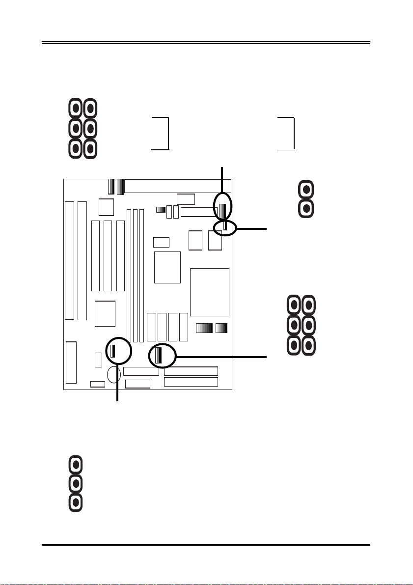
5-5-4 FAN, CD IN, IR, WOL Connector
CPU FAN SYS FAN
A. CPU & System Cooling FAN Connector:
This connectors support a CPU cooling fan of 500 mA (6WATT, +12V)
orless.Orient the fan so thattheheat sink fins allow airflowtogo across
the onboard heat sink(s). Depending on the fan manufacturer, the wir-
ing and plug may be different. The red wire should be positive (+12V),
while the black should be ground. Connect the fan’s plug to the board
taking into consideration the polarity of the connector.

20
User’ s Manual Rev. A
B. IrDA Compliant Infrared Module Connector
This connector support the optional wireless transmitting and receiving
infrared module. This module mounts to a small opening on system
cases that support this feature. You must also configure UART 2. Use
Infraredin Chipset Features Setupto select whetherUART2 is directed
for use with COM2 or IrDA. When IrDA is selected in BIOS, COM2 will
be disabled. Use the five pins as shown and connect a ribbon cable
from the module to the motherboard to the pin definitions.
Pin 1 Vcc
Pin 2 NC
Pin 3 IR_RX
Pin 4 GND
Pin 5 IR_TX
C. Wake-On-LAN (WOL)
Attachthe 3-pin connector from the LAN card which supports the Wake-
On-LAN (WOL) function to the WOL connector on the motherboard.
This WOL function lets users wake up the connected computer through
the LAN card. Please install according to the following pin assignment:
D. CD IN Connector
Provied 2 CD Audio Input Connectors that depending on the Cable
user have which connect from CDROM to This Connector
Table of contents
Other ENPC Motherboard manuals


