ENPC EP-KL11 User manual

EP-KL11
Motherboard of
Pentium II with MMX
User’s Manual
Order Number 41010008
January 1998
EC-Conformity Declaration
(EC conformity marking)
FOR THE FOLLOWING EQUIPMENT
Product Name MOTHERBOARD
Model EP-KL11
Manufacturer Address 6FL., No. 19, Wu Chuan 6 Rd.
Wu-Ku Industrial Park, Taipei, Taiwan,
R.O.C.
IS HEREWITH CONFIRMED TO COMPLY WITH THE EQUIPMENTS
SET UP IN THE COUNCIL DIRECTIVE ON THE APPROXIMATION
OF THE LAW OF MEMER STATES RELATING TO
ELECTROMAGNETIC COMPATIBILITY (89/336/EEC) AND LOW
VOLTAGE DIRECTIVE 78/28/EEC. FOR THE EVALUATION
REGARDING THE ELECTROMAGNETIC COMPATIBILITY AND
SAFETY, THE FOLLOWING STANDARDS WERE APPLIED
EN50081-1 (1992) GENERIC EMISSION STANDARDS
EN550022 (1994) EMISSION
EN60555-2 (1987) HARMONICS
EN60555-3 (1987) VOLTAGE FLUCTUATIONS
EN50082-1 (1992) GENERIC IMMUNITY STANDARD
IEC 801-2 (1984) ELECTROSTATIC DISCHARGE IMMUNITY
IEC 801-3 (1984) RADIATED IMMUNITY
IEC 801-4 (1988) ELECTRICAL FAST TRANSIENT
The manufacturer also declares the conformity of the above-mentioned
product, with the actual required safety standards in accordance with LVD
73/23 EEC.
Manufacturer/Importer
Date
Signature ___________________ Signature .
Name Jeff Chang Name Kunnau Chen

(Project Leader) (President)

EP-KL11
Motherboard
for
Compatible PC
User Manual Rev 1.0
Related Motherboard EP-KL11 P.C.B. Rev 1.X
Date Jan. 1998
EP-KL11 ser’s Manual
i

TABLE OF CONTENTS
Chapter 1.............................................................................................1
1-1 About this Manual……......................................................................1
1-2 Item Checklist…………....................................................................2
1-3 Specifications………….....................................................................3
Chapter 2.............................................................................................6
2-1 Motherboard Description...................................................................6
2-2 Motherboard Layout……..................................................................7
2-3 System Memories……….............................................................…..8
2-4 Central Processing Unit (CPU)........................................................10
2-5 Expansion Cards & Slots.................................................................12
2-6 External Connectors…….................................................................13
2-7 Hardware Jumper/Switch Setup.......................................................25
EP-KL11 ser’s Manual
ii

FCC & DOC COMPLIANCE
Federal Communications Commission Statement
This device complies with FCC Rules Part 15. Operation is subject to
the following two conditions
This device may not cause harmful interference, and
This device must accept any interference received, including
interference that may cause undesired operation.
This equipment has been tested and found to comply with the limits
for a Class B digital device, pursuant to Part 15 of the FCC Rules.
These limits are designed to provide reasonable protection against
harmful interference in a residential installation. This equipment
generates, uses and can radiate radio frequency energy and, if not
installed and used in accordance with manufacturer’s instructions,
may cause harmful interference to radio communications. However,
there is no guarantee that interference will not occur in a particular
installation. If this equipment does cause harmful interference to radio
or television reception, which can be determined by turning the
equipment off and on, the user is encouraged to try to correct the
interference by one or more of the following measures
Re-orient or relocate the receiving antenna.
Increase the separation between the equipment and receiver.
Connect the equipment to an outlet on a circuit different from that to
which the receiver is connected.
Consult the dealer or an experienced radio/TV technician for help.
Warning: The use of shielded cables for connection of the monitor to
the graphics card is required to assure compliance with FCC
regulations. Changes or modifications to this unit not expressly
approved by the party responsible for compliance could void the
user’s authority to operate this equipment.
EP-KL11 ser’s Manual
iii

Federal Communications Commission (Continued...)
Canadian Department of Communications Statement
This digital apparatus does not exceed the Class B limits for radio
noise emissions from digital apparatus set out the Radio Interference
Regulations for the Canadian Department of Communications.
EP-KL11 ser’s Manual
iv

1
Chapter 1 INTROD CTION
1-1 About this Manual
This manual is arranged to help you set up and run this Motherboard
of Pentium II with MMX as soon as possible.
The information is presented in the following two chapters
Chapter 1 Introduction:
Presents what you should receive with your
motherboard, the features and specifications
of the product. This chapter enclosed with a
diagram showing the layout of the
motherboard.
Chapter 2 Installation:
Motherboard Installation includes detailed
information on how to install and configure
the motherboard.
EP-KL11 User’s Manual

Chapter 1 INTROD CTION
1-2 Item Checklist
This product comes with the following components
Motherboard x 1
40-pin IDE Connector Flat Cable x 1
34-pin Floppy Disk Drive Flat Cable x 1
Bracket with 25-pin serial port and PS/2 Mouse ribbon cable x 1
User’s Manual x 1
CPU Retention Mechanism Kit x 1
Bracket with Com Port and Printer Port Flat cable x 1
Bus Master IDE/Ultra DMA-33 Drivers Diskette x 1 (Option)
IrDA Module x 1 (Option)
LDCM Diskette x 1 (Option)
USB Connector Cable with bracket x 1 (Option)
Option Components will be included upon customer ordering
instructions per Proforma Invoice & additional external
procurement cost will be included.
EP-KL11 ser’s Manual
2

3
Chapter 1 INTROD CTION
1-3 Specifications
Processor: Slot 1 support Intel Pentium II with MMX
Series CPU’s, CPU Clock Select support for
66 MHz CPU Bus speed configuration.
Chipset: Intel 82443LX System Controller
Intel 82371AB PCI/ISA IDE Accelerator
BIOS Award BIOS With Flash ROM, support PnP,
PCI 2.1, CD-ROM, ATAPI, LS-120, and any
IDE Device Bootable, Virus Protection, DMI
Ready
System Memory: 3 x 168-pin DIMM Slots Support Mixed
Memory Technologies Extended Data Output
(EDO), Fast Page (FP) DRAM), Synchronous
DRAM (SDRAM)
Multi-I/O Onboard: 1 x FDD Port support up to 2.88MB
1 x Parallel Port (LPT) support ECP/EPP
2 x High Speed Serial (16C550 UART) Ports
2 x Universal Serial Bus (USB) Ports
1 x AT Keyboard Port
1 x PS/2 Mouse Port
1 x IrDA Infrared Interfaces
EP-KL11 User’s Manual

Chapter 1 INTROD CTION
PCI Bus Master IDE: PCI Enhanced IDE Interface with 4 IDE
Devices
Support HDD Auto-Detect
Support up to PIO Mode 4, DMA Mode 2
Support Ultra DMA/33 mode
Fully compatible with PCI Local Bus
Specifications V2.1
I/O Connector: 2 x USB Ports, 1 x AT Keyboard Port, 1 x
PS/2 Mouse Port, 1 x Parallel Port, 2 x Com
Port
Expansion Slots: 3 x 16-bit ISA Slots with 100% ISA
Compatible Functions
3 x 32-bit PCI Slots supporting PCI BUS
Master Slots Conform with PCI
Specifications Version 2.1
1 x AGP Slot supported.
Options: 1 x Infrared (IrDA) Wireless Interface Kit
(Front & Rear)
Universal Serial Bus (USB) Connector Kit
LM78 Hardware Monitor Circuit Design and
LM75 CPU Temperature reading, LDCM
for system Voltage, System Temperature,
Fan Speed detect.
EP-KL11 ser’s Manual
4

5
Chapter 1 INTROD CTION
Extended Features: Advanced Configuration and Power Interface
(ACPI) ready
CPU Temperature detect
Support System Power Monitor
Support Win95 Soft Power Off (For ATX
Power only)
Support SM-Bus
Dimension: 220 mm x 240 mm
Form Factor: Baby AT Form Factor
EP-KL11 User’s Manual

Chapter 2 INSTALLATION
2-1 Motherboard Description
The motherboard is designed with the Intel 82440LX PCI chipset
which is developed by Intel Corporation to fully support the
Pentium II Processor PCI/ISA system. The Intel 82440LX PCI chipset
provides increased integration and improved performance designs.
The chipset provides an integrated IDE controller with two high
performance IDE interfaces for up to four IDE devices (hard devices,
CD-ROM device, etc). The Super I/O controller provides the standard
PC I/O function floppy interface, two 16Byte FIFO serial ports and
EPP/ECP capable parallel port.
Care must be taken when inserting memory modules, inserting CPU
or even plugging PCI card into associated slots to avoid damaging any
circuits or sockets on board. A cooling fan is strongly recommended.
The motherboard supports minimum of 8MB of system memory and a
maximum of 512MB SDRAM, 1GB EDO RAM.
The motherboard supports standard Fast Page (FP), EDO (Extended
Data Output), or SDRAM (Synchronous DRAM). The motherboard
provides three 168-pin DIMM.
The board also supports onboard two PCI IDE connectors, and detects
the IDE hard disk type by the BIOS utility which is automatic. The
system also supports Award Plug & Play BIOS for the ISA and PCI
cards.
EP-KL11 ser’s Manual
6
7
Chapter 2 INSTALLATION
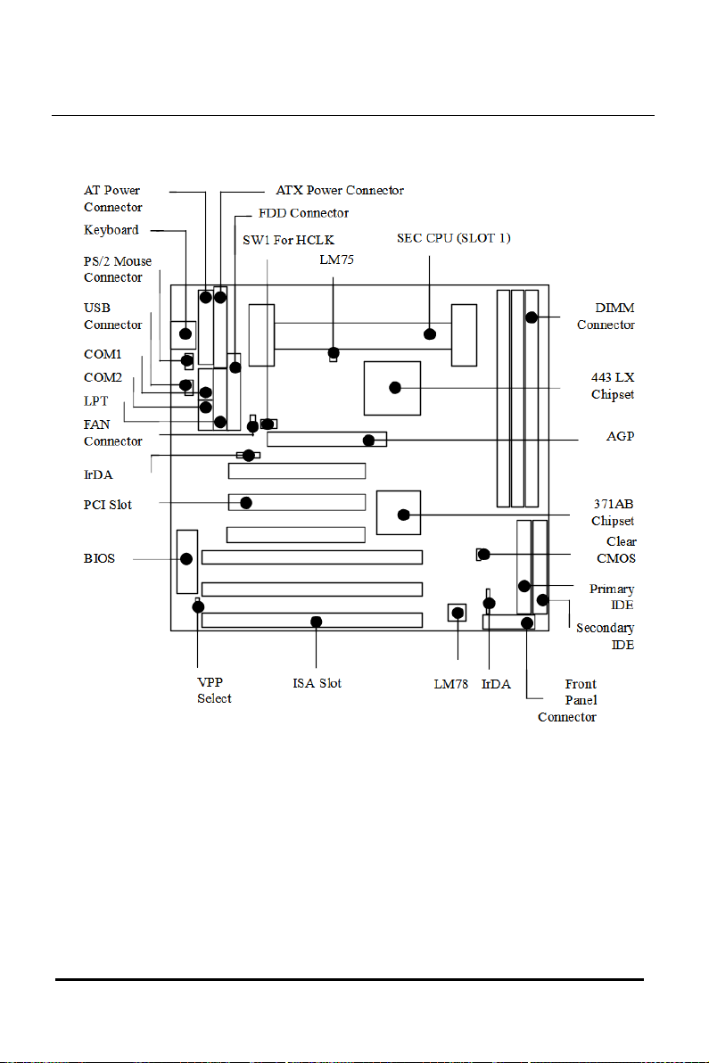
2-2 Motherboard Layout
EP-KL11 User’s Manual

Chapter 2 INSTALLATION
2-3 System Memories
This motherboard only supports Dual Inline Memory Modules
(DIMM’S), The Dual Inline Memory Module (DIMM) must be 3.3
Volt Unbuffered Synchronous DRAM (SDRAM) or Exteded Data
Output (EDO) DRAM of either 16, 32, 64, or 128MB to form a
memory size between 16MB to 384MB.
Note 1. Install memory in any combination as next page
EP-KL11 ser’s Manual
8
9
Chapter 2 INSTALLATION
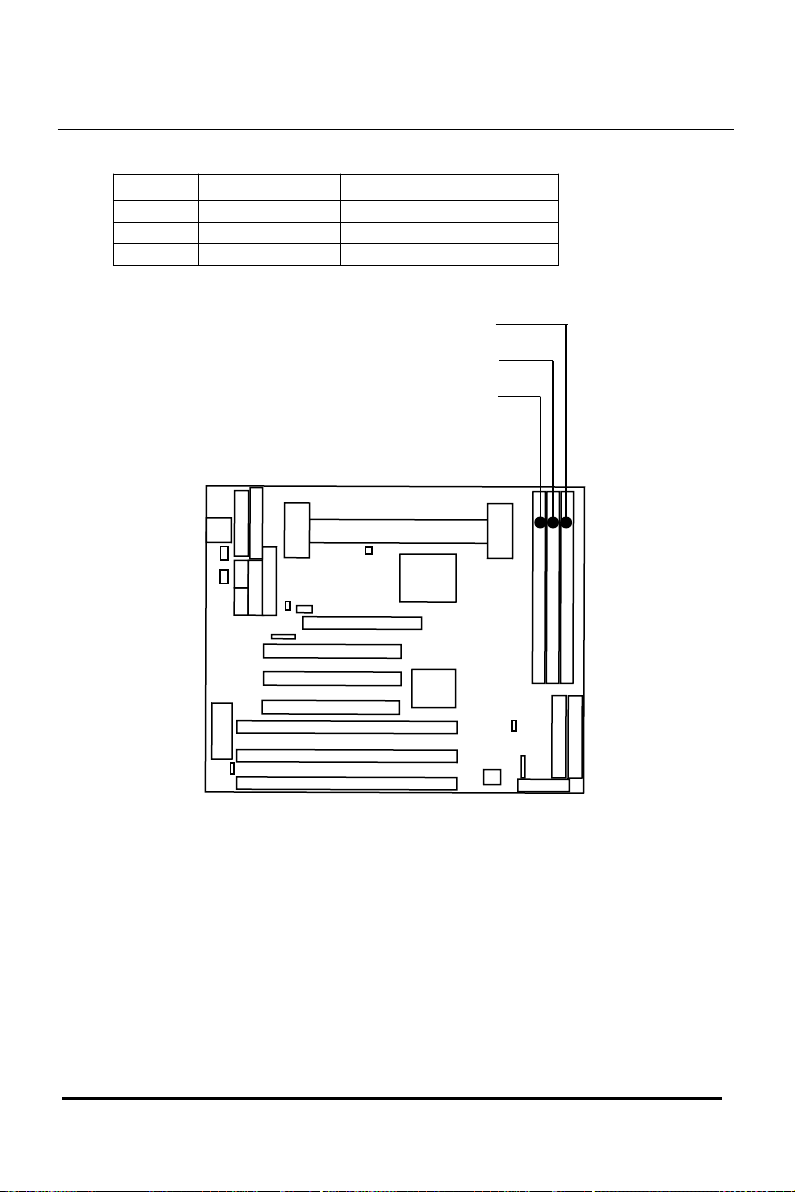
Item Bank Memory Module
1 DIMM 1 16~128MB
2 DIMM 1, 2 16~128MB
3 DIMM 1, 2, 3 16~128MB
EP-KL11 User’s Manual
DIMM 2
DIMM 1
DIMM 3
Chapter 2 INSTALLATION
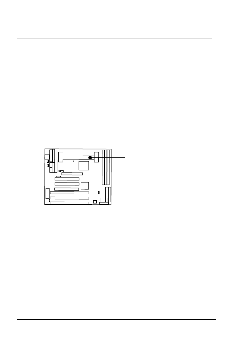
2-4 Central Processing nit (CP )
The motherboard provides a SLOT 1 for Pentium II CPU. The CPU
should have a fan attached to it to prevent overheating. If your CPU
did not come with a fan, then purchase a fan before you turn on your
system.
NOTE Without a fan, the CPU can overheat and cause damage
to both the CPU and the motherboard.
EP-KL11 ser’s Manual
SLOT 1
10
11
Chapter 2 INSTALLATION
To install a CPU, locate the SLOT 1. Insert the CPU with the correct
orientation. you should have a CPU fan that will cover the face of the
CPU.
EP-KL11 User’s Manual
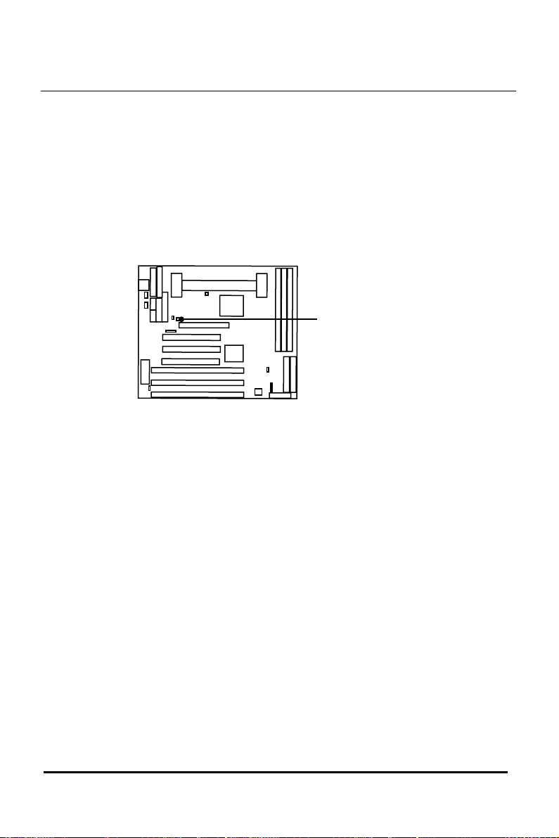
SW1 (Use pin header )
CPU Bus Clock Select

Chapter 2 INSTALLATION
2-5 Expansion Cards & Slots
Assigning DMA Channels for ISA Cards
Some ISA cards, both Legacy and PnP may also need to use a DMA
(Direct Memory Access) channel. DMA assignments for this
motherboard are handled the same way as the IRQ assignment process
. You can select a DMA channel in the PCI and PnP configuration
section of the BIOS Setup utility.
NOTE Choose “Legacy ISA” for those IRQ’s and DMA’s you
wish to reserve for Legacy (Non-PnP) ISA expansion
cards in “IRQ xx Used by ISA” and “DMA x Used By
ISA” of the PnP and PCI Setup in the BIOS Software
section, otherwise conflicts may occur.
EP-KL11 ser’s Manual
3 x PCI SLOTS
3 x ISA SLOTS
12

13
Chapter 2 INSTALLATION
2-6 External Connectors
1. Keyboard Connector and SB Port (K/B, 5-pin female
connector and USB, 8-pin Pin header)
This K/B connection is for a standard AT Keyboard connector
This USB connector will use USB connector kit. You may order
from your distribute.
2. PS/2 Mouse Connector (PS/2, 6-pin Pin header )
If you are using a PS/2 mouse, you must enable the PS/2 port in
the BIOS Setup.
Pin 1 VCC
2 NC
3 NC
4 (BLANK)
5 MSDAT
6 (BLANK)
7 GND
8 MSCLK
EP-KL11 User’s Manual
Note The USB Port Support Standard USB Spec.
Pin #1
USB Pinout
1 USBV0
2 USBV1
3 USBD0-
4 USBD1-
5 USBD0+
6 USBD1+
7 USBG0
8 USBG1
PS/2 Mouse
Connector
Pin #1
K/B Keyboard
Port
USB Port
Pin #2
Pin #2
Table of contents
Other ENPC Motherboard manuals


