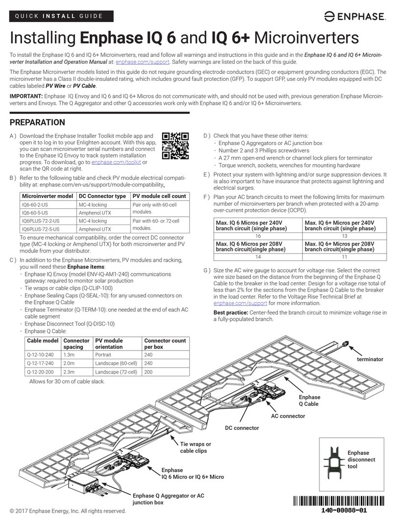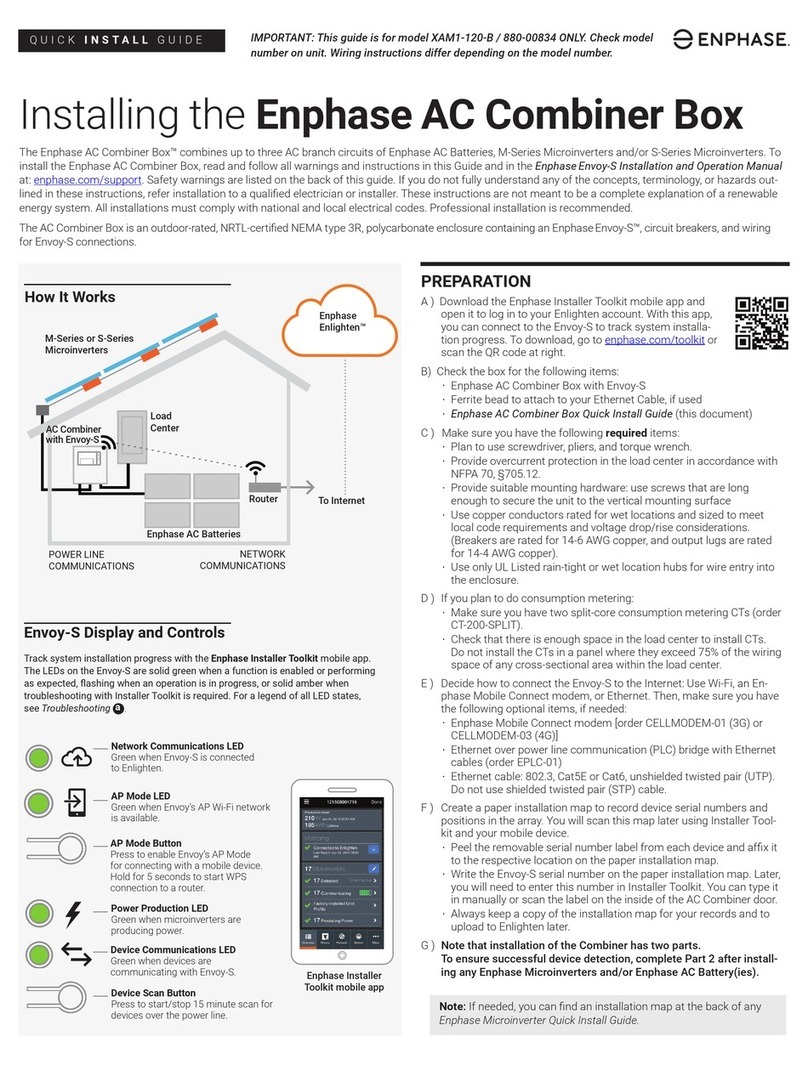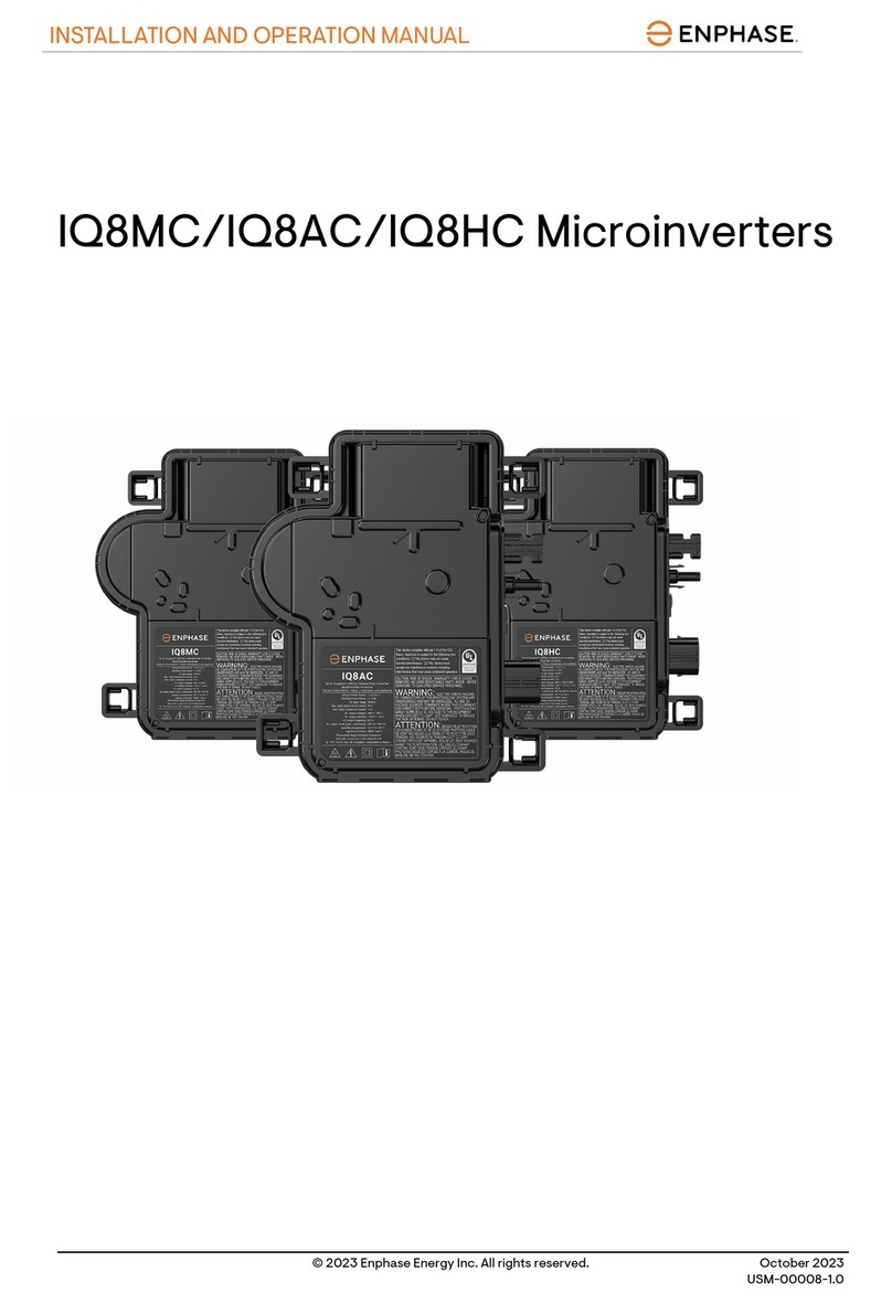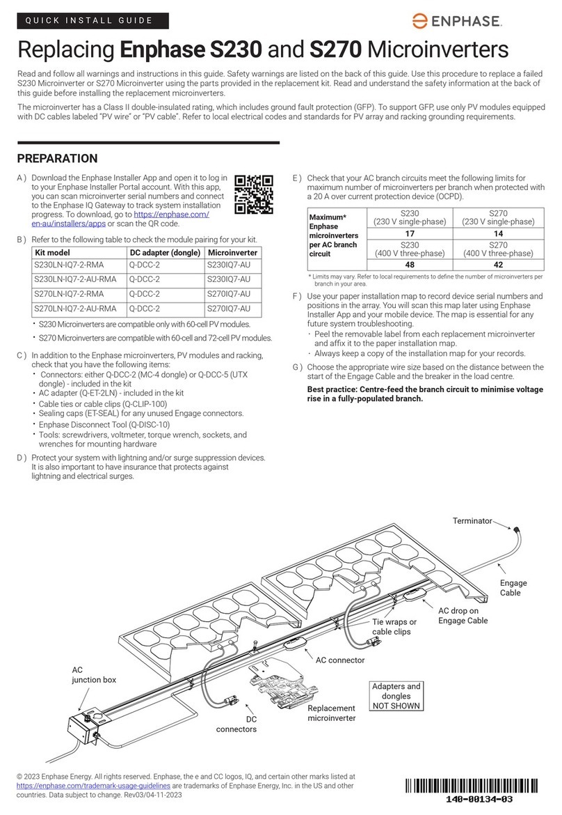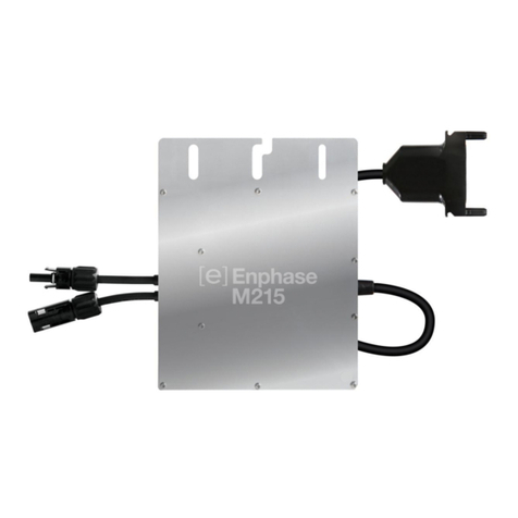
M215 Installation and Operation
Copyright 2012 Enphase Energy 141-00012 Rev 04
3
Table of Contents
Important Safety Information ................................................................................................................................ 4
The Enphase Microinverter System .....................................................................................................................5
How the Microinverter Works..................................................................................................................6
System Monitoring ..............................................................................................................................6
Optimal Reliability ...............................................................................................................................6
Ease of Design.................................................................................................................................... 6
Enphase Microinverter Installation ....................................................................................................................... 7
Compatibility and Capacity.....................................................................................................................7
Parts and Tools Required .......................................................................................................................7
Enphase equipment: ..........................................................................................................................8
Other items: ........................................................................................................................................8
Lightning Surge Suppression .................................................................................................................8
Installation Procedure ............................................................................................................................. 9
Step 1 – Measure AC at the Electrical Utility Connection ......................................................................9
Step 2 – Install the AC Branch Circuit Junction Box ............................................................................10
Step 3 – Position the Enphase Engage Cable .....................................................................................11
Step 4 – Attach the Microinverters to the PV Racking..........................................................................12
Step 5 – Dress the Engage Cable ........................................................................................................13
Step 7 – Terminate the Unused End of the Engage Cable..................................................................15
Step 8 – Connect the Engage Cable to AC Junction Box(es) .............................................................16
Step 9 – Ground the System.................................................................................................................17
Step 10 – Complete the Installation Map .............................................................................................18
Complete the Installation Map..........................................................................................................18
Alternative: Create Your Own Map ..................................................................................................18
Step 11 – Connect the PV Modules......................................................................................................18
Step 12 – Build the Virtual Array ...........................................................................................................19
Commissioning and Operation ..........................................................................................................................20
Commissioning .....................................................................................................................................20
Operating Instructions ..........................................................................................................................20
Troubleshooting..................................................................................................................................................21
Status LED Indications and Error Reporting.........................................................................................21
Startup LED Operation: ....................................................................................................................21
Post-Startup LED Indications: ..........................................................................................................21
GFDI Fault:........................................................................................................................................21
Other Faults: .....................................................................................................................................21
Troubleshooting an Inoperable Microinverter.......................................................................................22
Disconnecting a Microinverter from the PV Module .............................................................................23
Installing a Replacement Microinverter ................................................................................................24
Technical Data....................................................................................................................................................25
Technical Considerations .....................................................................................................................25
Technical Specifications .......................................................................................................................26
Enphase M215 Microinverter Parameters ........................................................................................26
Enphase Installation Map .....................................................................................................................28
Sample Wiring Diagram – M215, 240 VAC...........................................................................................29
Sample Wiring Diagram – M215, 208 VAC...........................................................................................30


