entegris 4000 Series User manual
P/N 01-1027289 | REV. A 04/17
NT Pressure Transducer
Models 4100, 4210
User Guide

NT PRESSURE TRANSDUCER MODELS 4100, 4210
1Entegris, Inc. | User Guide
Table of Contents
Safety Alert Symbol ........................ 2
Introduction ..................................... 2
Installation ........................................ 3
Mechanical Installation ................ 3
Electrical Installation .................... 4
Power Supply
Requirements ................................. 4
Warnings ......................................... 5
Unit Operation ................................. 6
Operating Environment ............... 6
Process Connections ................... 6
Pressure Transducer
Cover Assembly ............................. 6
Pressure and Temperature
Requirements ................................. 6
Pressure Limits ............................... 7
Pressure Reference
Accuracy ......................................... 7
Linear Output Signal .................... 8
Troubleshooting .............................. 9
Reference ....................................... 10
Physical Specifications ............... 10
Electrical Specifications ............. 10
Performance
Specifications ............................... 10
Certifications .................................. 11
CE Compliance ........................... 11
Class I, Division 2
Hazardous Environments ......... 11
Ordering Information .................. 12
Model 4100 Single-port ............ 12
Model 4210 Flow-through ......... 13
Installation Drawings ................... 14
Model 4100 Single-port ............ 14
Model 4210 Flow-through ......... 15
Control Drawing ......................... 17
Appendix ......................................... 18
For More Information .................. 22
Terms and Conditions of Sale .... 22
Product Warranties ....................... 22

NT PRESSURE TRANSDUCER MODELS 4100, 4210
2User Guide | Entegris, Inc.
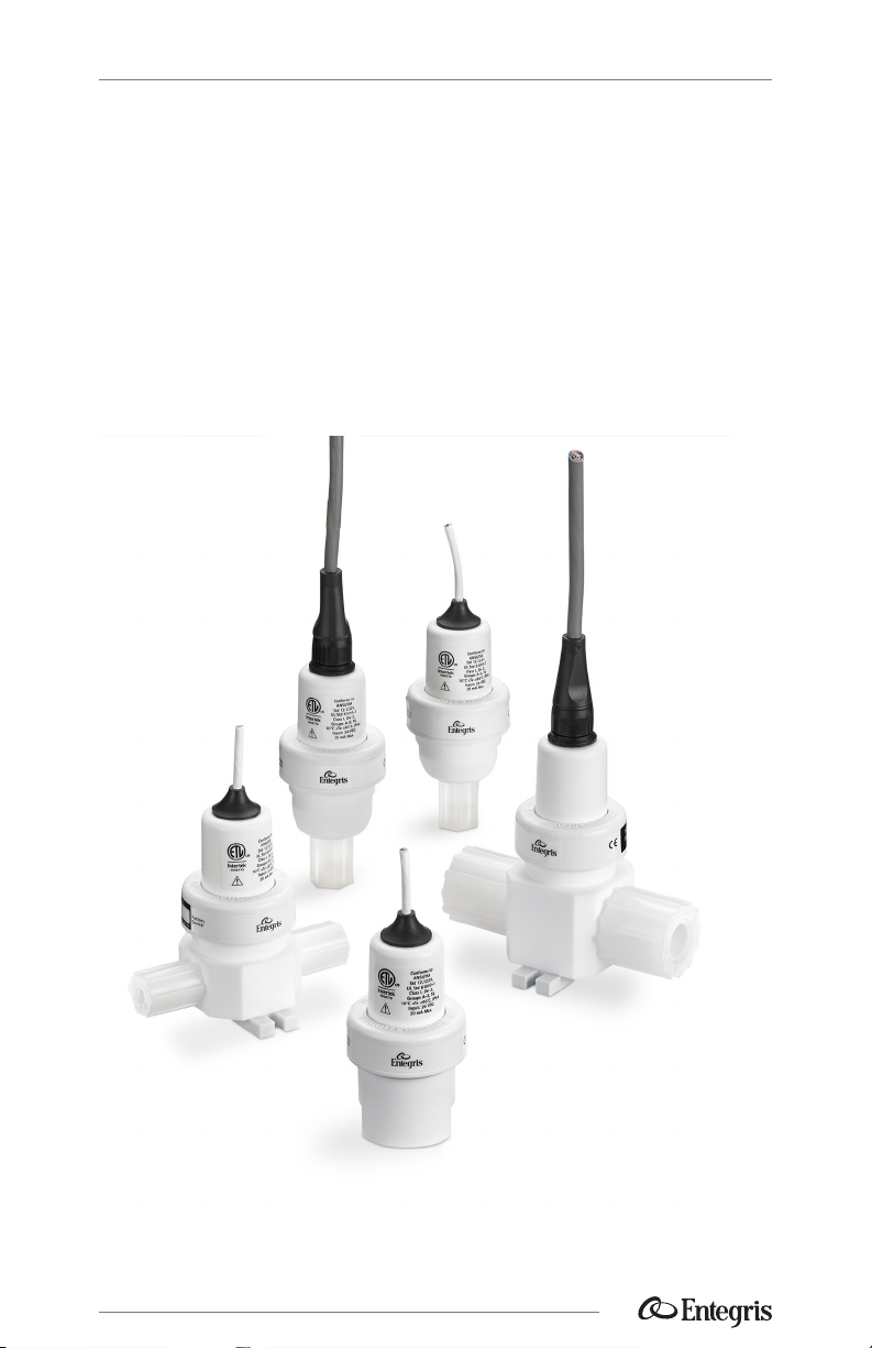
Introduction
This manual is for use with the
following standard NT Pressure
Transducer 4000 Series Models
4100 and 4210. These instruments
have been designed for use in high
purity applications in the semicon-
ductor industry.
These products feature no moving
parts and no filled cavities, which
reduces the possibility of a contami-
nated process. The wetted parts of
these nonmetallic transducers are
constructed with PTFE, PFA or other
similar high purity inert materials.
WARNING! Attempting to install
or operate standard NT 4000
Series Pressure Transducers
without reviewing the instruc-
tions contained in this manual
could result in personal injury or
equipment damage.
Polypropylene electrical
connector option
Signal conditioning circuit
Electronic pressure senso
r
Process connection
PTFE body
Cut-away Example:
NT Single-port
Pressure Transducer
Cut-away Example:
NT Flow-through
Pressure Transducer
Process
connection
Polypropylene
electrical
connector option
Signal condition-
ing circuit
Electronic
pressure sensor
PTFE body
Safety Alert Symbol
Indicates a hazardous situation which, if not avoided,
could result in serious injury or death.
WARNING!

NT PRESSURE TRANSDUCER MODELS 4100, 4210
3Entegris, Inc. | User Guide
Installation
WARNING! The pressure trans-
ducer has been factory sealed.
Do not attempt to remove the
cover of the pressure transducer.
Any attempt at removal of the
pressure transducer cover
will void the warranty and
damage the unit.
WARNING! Do not tighten the
nuts that protect the process
connections during shipment.
Do not tighten the nuts unless the
proper tubing has been installed.
Tightening these nuts may result in
damage to the pressure transducer
process connections.
MECHANICAL INSTALLATION
—
NOTE: For detailed tube flaring
instructions, see “Flaretek tube
fitting flare and assembly procedure”
at www.entegrisfluidhandling.com
(follow the Fittings>Tube Fittings>
Flaretek Tube Fittings links).
When installing flared tubing to
the pressure transducer, the flared
tube is pushed over the transducer’s
fitting until the fitting reaches the
smaller tube diameter. The amount
of torque required to tighten the
coupling nut is dependent upon
the size of the fitting.
Fitting size 1⁄4"3⁄8"1⁄2"3⁄4" 1"
Torque (in•lbs) 5 8 11 14 30
Care should be taken when instal-
ling flared tubing onto the pressure
transducer. Do not use excessive
torque or subject the transducer
to high heat during installation.
The transducer should be firmly
mounted to a solid surface to
ensure stability. Verify that the
pressure transducer and the signal
cable are free from mechanical
stress or excessive bending from
the surrounding equipment.

NT PRESSURE TRANSDUCER MODELS 4100, 4210
4User Guide | Entegris, Inc.
ELECTRICAL INSTALLATION
—
The pressure transducer provides
an analog (0–5 VDC, 0–10 VDC or
4–20 mA) electrical output propor-
tional to the pressure measured.
NOTE: The white wire is not required
for the 4–20 mA output configuration,
please refer to the wiring diagrams below.
POWER SUPPLY REQUIREMENTS
—
The pressure transducer requires
a 12–30 volt DC power supply with
less than 2% ripple at 100 or 120 Hz.
The required power supply voltage
varies with the load resistance (RLoad),
please refer to the formulas on page
5. The power supply must provide
clean power and must be used only
to power similar measurement-type
devices. The power supply must not
be used to power inductive loads,
such as motors, relays or solenoids.
These devices may produce
transients that may aect the
pressure transducer measurements
when the inductive device is powered
up or powered down.
NOTE: Be sure to ground the shield of
the cable to local ground.
+24 VDC
Pressure transducer
4–20 mA output version
Pressure transducer
0–5 VDC, 0–10 VDC output version
4–20 mA pressure signal
Voltage pressure signal
RED
WHITE
GND
BLACK
RED
WHITE
BLACK
No connection
Display
or PLC
Display
or PLC
Electrical connector information
WIRE 4–20 MA OUTPUT VERSION VOLTAGE OUTPUT VERSION
Red VDC+ 24 VDC (12–30 VDC) 24 VDC (12–30 VDC)
Black VDC– Ground Ground
White Not used 0–5 VDC signal or 0–10 VDC signal
NT PRESSURE TRANSDUCER MODELS 4100, 4210
5Entegris, Inc. | User Guide
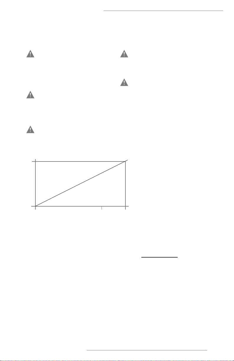
Load Resistance: Current Output
(4–20 mA Configuration)
If a load resistor, RLoad, is used
in series with the current output,
the value of RLoad is dependent on
the supply voltage and the meter
resistance and is calculated from
the following formula:
Load Resistance: Voltage Output
(0–5, 0–10 VDC)
The output impedance is 1 kOhm.
The input impedance should
be ≥1 megohm for ±0.1% load
impedance error.
850
12 24 29
Power supply
voltage
(VPS)
Operating
region
RLoad (Ohms)
0
Figure 1. Power required for a 4–20 mA loop.
R
Load = – Rmeter
RLoad
Rmeter
where:
= maximum load
resistance (ohms)
= power supply
voltage (volts)
= meter resistance (ohms)
(theoretically = 0)
VPS
V
PS
– 12 V
20 mA
WARNINGS
—
WARNING! For use in Class I
Division 2 Hazardous Environ-
ments, models with disconnecting
cable options must be wired in
accordance with the control
drawing 01-1033562 on page 17.
WARNING! Do not remove or
replace while circuit is live unless
the area is known to be free
of ignitible concentrations of
flammable substances.
WARNING! Do not replace comp-
onents unless power has been dis-
connected or the area is known to
be free of ignitible concentrations.
WARNING! Explosion hazard.
Do not connect while the circuit is
live or unless the area is known to
be free of ignitible concentrations.
WARNING! Substitution of com-
ponents may impair suitability for
Division 2.

NT PRESSURE TRANSDUCER MODELS 4100, 4210
6User Guide | Entegris, Inc.
Unit Operation
OPERATING ENVIRONMENT
—
The pressure transducer is to
be mounted in a well vented and
controlled environment. Refer to
the Reference section on page 10
for additional specifications.
PROCESS CONNECTION
—
To avoid possible pressure leaks,
make sure all process connections
have been performed in accordance
with the Mechanical Installation
guidelines on page 3.
PRESSURE TRANSDUCER COVER
ASSEMBLY
—
NT Pressure Transducer covers are
factory sealed and should not be
tampered with or opened. Opening
the cover shall void the product
warranty.
WARNING! Any attempt to remove
or tamper with the transducer
cover will void the warranty
and damage the unit.
PRESSURE AND TEMPERATURE
REQUIREMENTS
—
The minimum pressure required
is atmospheric pressure. The pres-
sure transducer may be damaged
if subjected to vacuum pressure
(pressure that is less than atmo-
spheric pressure).
The pressure transducer is rated for
use with fluids at process tempera-
tures between 10–65°C (50–149°F)
under normal operating conditions.
WARNING! NT Pressure Transduc-
ers, Models 4100 and 4210 may be
damaged if the sensor is subjected
to any level of vacuum pressure
(pressure less than atmospheric
pressure).

NT PRESSURE TRANSDUCER MODELS 4100, 4210
7Entegris, Inc. | User Guide
PRESSURE LIMITS
—
TRANSDUCER
RANGE
MAXIMUM OVER PRESSURE
LIMIT @ 23°C (73°F)
MAXIMUM OVER PRESSURE
LIMIT @ 65°C (149°F)
0 – 30 psig 690 kPa (100 psig) 690 kPa (100 psig)
0 – 60 psig 1034 kPa (150 psig) 690 kPa 100 psig
0 –100 psig 1034 kPa (150 psig) 690 kPa 100 psig
0 –150 psig 1310 kPa (190 psig) N/A
Maximum over pressure can be limited by the fitting. Consult the fitting specification for
maximum over pressure limits.
WARNING! The pressure limits
for standard NT Pressure Trans-
ducers (4000 Series) decrease
significantly for temperatures
above 65°C (149°F). Exceeding
these limits may result in personal
injury or equipment damage.
PRESSURE REFERENCE ACCURACY
—
The accuracy of the pressure
transducer output is ±1% of full
scale. This accuracy includes the
eects of linearity, hysteresis and
repeatability, measured at room
temperature. Accuracy specifica-
tions for non-standard product
configurations might vary.
NT PRESSURE TRANSDUCER MODELS 4100, 4210
8User Guide | Entegris, Inc.
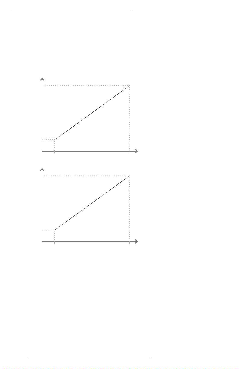
LINEAR OUTPUT SIGNAL
—
The output signal of the pressure
transducer is a linear function
proportional to the applied pressure.
Full scale
4 mA
0 psig Pressure
Measurement
Full scale0 psig Pressure
Measurement
Current Output (mA)Voltage Output (V)
20 mA
10 V
or 5 V
0V

NT PRESSURE TRANSDUCER MODELS 4100, 4210
9Entegris, Inc. | User Guide
Troubleshooting
Troubleshooting the NT Pressure
Transducers (4000 Series) may
be accomplished by measuring
the output signal of the pressure
transducer with a battery powered
current/voltage meter. The meter
may be placed in series with the
pressure transducer to measure the
current output or it may be used to
directly measure the voltage output.
Using the battery powered current/
volt meter is an eective method to
determine whether the device or the
on-site data acquisition system is not
functioning properly.

NT PRESSURE TRANSDUCER MODELS 4100, 4210
10 User Guide | Entegris, Inc.
Reference
The following lists the specifications
for the NT Pressure Transducer
product line. Please consult the
factory for product specifications
manufactured for nonstandard
applications.
NOTE: Specifications are subject to
change without notice.
Physical Specifications:
Materials Wetted parts Body PTFE
Sensor interface CTFE or PFA
O-ring Kalrez®
Nonwetted
parts
Polypropylene, polyethylene, Viton®, PVDF
(in addition to materials listed above)
Connection type Flaretek tube fitting, Super 300 Type Pillar®tube fitting, NPT
(PrimeLock®available upon request.)
Electrical Specifications:
Input voltage 24 VDC (12–30 VDC)
Input current 20 mA maximum
Pressure signal output ranges 4–20 mA, 0–5 VDC, 0–10 VDC
Electrical connection 6', 12', 30' FEP-jacketed pigtail or polypropylene
3-pin connector
Electrical enclosure IP54
Performance Specifications
Reference accuracy ±1% of full scale (includes linearity, hysteresis and
repeatability) at 23°C (73°F)
Process temperature 10–65°C (50–149°F)

NT PRESSURE TRANSDUCER MODELS 4100, 4210
11Entegris, Inc. | User Guide
Certifications
CE COMPLIANCE
Entegris products have been tested
to various test standards required
by the EMC 2104/30/EU directive.
The results of this testing are on
file at Entegris and are available
upon request.
Please contact the factory for
the latest information. The most
current specifications may be
found on Entegris’ Web site at:
http://www.entegrisfluidhandling.
com/Product.aspx?G=1613
CLASS I DIVISION 2
HAZARDOUS ENVIRONMENTS
Entegris has tested our standard
products to the UL 61010-1,
ANSI/ISA 12.12.01 standards for
use in Class I, Division 2 Group A–D,
T6 10°C ≤Ta ≤65°C hazardous
environments. The results of this
testing are on file at Entegris and
are available upon request.
All specifications are subject to
change. Please contact the factory
for the latest information.

NT PRESSURE TRANSDUCER MODELS 4100, 4210
12 User Guide | Entegris, Inc.
Ordering Information
Refer to the following for the desired configuration.
Model 4100 Single-port Pressure Transducer: part number
4100 - - - - - -
Pressure range
030G = 207 kPa (30 psig)
060G = 414 kPa (60 psig)
100G = 690 kPa (100 psig)
150G = 1034 kPa (150 psig)
(Flaretek and Pillar
port connections
only)
Inlet/outlet port connection
F02 =
1⁄4" Flaretek tube fitting
F03 =
3⁄8" Flaretek tube fitting
F04 =
1⁄2" Flaretek tube fitting
W02 = 1⁄4" Super 300 Type Pillar tube fitting
W03 =
3⁄8" Super 300 Type Pillar tube fitting
W04 =
1⁄2" Super 300 Type Pillar tube fitting
N02 =
1⁄4" FNPT
N04 =
1⁄2" FNPT
M02 = 1⁄4" MNPT
Electrical connector types
B06 = FEP-jacketed 6'pigtail electrical cable
B12 = FEP-jacketed 12'pigtail electrical cable
B30 = FEP-jacketed 30'pigtail electrical cable
D00 = Polypropylene connector (cable not included)
D06 = Polypropylene connector and 6'PVC cable
D12 = Polypropylene connector and 12'PVC cable
D30 = Polypropylene connector and 30'PVC cable
Primary/secondary seal
U3 = Kalrez 6375 UP / Viton
S3 = Kalrez 6375 UP / Kalrez 6375 UP
Sensor interface
P1 = CTFE sensor interface (default)
P2 = PFA sensor interface
Electrical outputs
A = 4–20 mA (12–30 VDC input)
B = 0–10 VDC (12–30 VDC input)
C = 0–5 VDC (12–30 VDC input)
Example: 4100-100G-F02-D06-A-P1-U3
• 4100 — Model
• 100G — Pressure range
• F02 — Inlet/outlet port connection
• D06 — Electrical connector type
• A — Electrical outputs
• P1 — Sensor interface
• U3 — Primary/secondary seal

NT PRESSURE TRANSDUCER MODELS 4100, 4210
13Entegris, Inc. | User Guide
Model 4200 Single-port Pressure Transducer: part number
4200- - - - - -
*For detailed pressure limit information on Flaretek tube fitting connections, refer to the
Maximum Pressure Capabilities chart in the Flaretek fittings product section on Entegris’
website at http://www.entegrisfluidhandling.com.
Pressure range
030G = 207 kPa (30 psig)
060G = 414 kPa (60 psig)
100G = 690 kPa (100 psig)
Inlet/outlet port connection
F02 =
1⁄4" Flaretek tube fitting
F03 =
3⁄8" Flaretek tube fitting
F04 =
1⁄2" Flaretek tube fitting
F06 =
3⁄4" Flaretek* tube fitting
F08 = 1" Flaretek* tube fitting
W02 = 1⁄4" Super 300 Type Pillar tube fitting
W03 =
3⁄8" Super 300 Type Pillar tube fitting
W04 =
1⁄2" Super 300 Type Pillar tube fitting
W06 = 3⁄4" Super 300 Type Pillar tube fitting
W08 = 1" Super 300 Type Pillar tube fitting
Electrical connector types
B06 = FEP-jacketed 6'pigtail electrical cable
B12 = FEP-jacketed 12'pigtail electrical cable
B30 = FEP-jacketed 30'pigtail electrical cable
D00 = Polypropylene connector (cable not included)
D06 = Polypropylene connector and 6'PVC cable
D12 = Polypropylene connector and 12'PVC cable
D30 = Polypropylene connector and 30'PVC cable
Primary/secondary seal
U3 = Kalrez 6375 UP / Viton
S3 = Kalrez 6375 UP / Kalrez 6375 UP
Sensor interface
P1 = CTFE sensor interface (default)
P2 = PFA sensor interface
Electrical outputs
A = 4–20 mA (12–30 VDC input)
B = 0–10 VDC (12–30 VDC input)
C = 0–5 VDC (12–30 VDC input)
Example: 4210-100G-F02-D06-A-P1-U3
• 4100 — Model
• 100G — Pressure range
• F02 — Inlet/outlet port connection
• D06 — Electrical connector type
• A — Electrical outputs
• P1 — Sensor interface
• U3 — Primary/secondary seal

NT PRESSURE TRANSDUCER MODELS 4100, 4210
14 User Guide | Entegris, Inc.
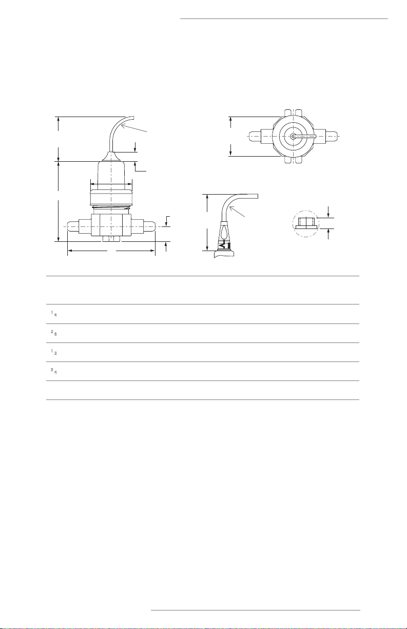
Installation Drawings
4100 Single-port Pressure Transducer
Inlet/outlet
port connection
A
B
1⁄4" Flaretek tube fitting 76.2 mm
(3.00")
25.2 mm
(0.99")
3⁄8" Flaretek tube fitting 76.2 mm
(3.00")
26.9 mm
(1.06")
1⁄2" Flaretek tube fitting 76.2 mm
(3.00")
29.0 mm
(1.14")
1⁄4" FNPT 82.3 mm
(3.24")
–
1⁄2" FNPT 88.9 mm
(3.50")
–
1⁄4" MNPT 76.2 mm
(3.00")
15.0 mm
(0.59")
1⁄4" Super 300 Type Pillar
tube fitting
76.2 mm
(3.00")
11.0 mm
(0.43")
3⁄8" Super 300 Type Pillar
tube fitting
76.2 mm
(3.00")
15.0 mm
(0.59")
1⁄2" Super 300 Type Pillar
tube fitting
76.2 mm
(3.00")
17.5 mm
(0.69")
Side View Side View Side View
Flaretek®Connection
10.7 mm (0.42”)
A
B
3 conductor
FEP-jacketed pigtail
connection (BXX)
(Cable length up
to 30 feet)
25.4 mm
(1.00”)
Ø47.8 mm
(1.88”)
Ø47.8 mm
(1.88”)
Super 300 Type Pillar®
Connection
10.7 mm
(0.42”)
NPT Connection
Ø47.8 mm
(1.88”)
25.4 mm
(1.00”)
25.4 mm
(1.00”)
A
B
A
B
Receptacle with connector removed
8.4 mm
(0.33”)
3 conductor
connector/cable
(DXX) (Cable length
up to 30 feet)
76.2 mm
(3.00”)
NT PRESSURE TRANSDUCER MODELS 4100, 4210
15Entegris, Inc. | User Guide
4210 Flow-through Pressure Transducer
Inlet/outlet
port connection
A
B
C
1⁄4" Flaretek tube fitting 89.7 mm (3.53") 94.7 mm (3.73") 18.5 mm (0.73")
3⁄8" Flaretek tube fitting 89.7 mm (3.53") 98.3 mm (3.87") 17.0 mm (0.67")
1⁄2" Flaretek tube fitting 96.0 mm (3.78") 102.4 mm (4.03") 21.6 mm (0.85")
3⁄4" Flaretek tube fitting 104.1 mm (4.10") 108.5 mm (4.27") 25.4 mm (1.00")
1" Flaretek tube fitting 112.5 mm (4.43") 120.7 mm (4.75") 30.5 mm (1.20")
Note: No NPT option on Model 4210.
Side View Top View
Flaretek Connection
10.7 mm
(0.42”)
A
BReceptacle with
connector removed
8.4 mm
(0.33”)
3 conductor pigtail
connection (BXX)
(Cable length
up to 30 feet)
3 conductor
connector/
cable (DXX)
(Cable length
up to 30 feet)
25.4 mm
(1.00”)
76.2 mm
(3.00”)
C
Ø47 mm
(1.85”)
44.5 mm
(1.75”)

NT PRESSURE TRANSDUCER MODELS 4100, 4210
16 User Guide | Entegris, Inc.
4210 Flow-through Pressure Transducer
Inlet/outlet
port connection
A
B
C
1⁄4" Super 300 Type Pillar
tube fitting
89.7 mm (3.53") 66.5 mm (2.62") 18.5 mm (0.73")
3⁄8" Super 300 Type Pillar
tube fitting
89.7 mm (3.53") 74.5mm (2.93") 17.0 mm (0.67")
1⁄2" Super 300 Type Pillar
tube fitting
96.0 mm (3.78") 79.5 mm (3.13") 21.6 mm (0.85")
3⁄4" Super 300 Type Pillar
tube fitting
104.4 mm (4.11") 88.4mm (3.48") 25.7 mm (1.01")
1" Super 300 Type Pillar
tube fitting
111.8 mm (4.40") 98.6mm (3.88") 29.7 mm (1.17")
Side View Top View
Super 300 Type Pillar Connection
10.7 mm
(0.42”)
A
B
8.4 mm
(0.33”)
25.4 mm
(1.00”)
76.2 mm
(3.00”)
C
44.5 mm
(1.75”)
Ø47 mm
(1.85”)
3 conductor
connector/
cable (DXX)
(Cable length
up to 30 feet)
Receptacle with
connector removed
3 conductor
FEP-jacketed pigtail
connection (BXX)
(Cable length up
to 30 feet)

NT PRESSURE TRANSDUCER MODELS 4100, 4210
17Entegris, Inc. | User Guide
Control Drawing 01-1033562
Nonincendive Field Wiring Required for Disconnecting Cable Options
A
03/22/2016
1
01-1033562
Control Drawing - Model 4100/4210
ENT
ENG MNGR:
MODIFIED BY:
ELEC ENG:
BAK
Entegris
B
1
REV:SIZE:CODE:
DRAWN: DATED:
DATED:
DATED:
DATED:
COMPANY:
TITLE:
DRAWING NO:
SHEET: OFSCALE:
REVISION RECORD
APPROVED:ECO NO:
A
B
D
DATE:
12345 6
D
C
A
B
C
LTR
Pressure
Hazardous (Classified) Location
Class I Division 2 Groups A, B, C, D
Unclassified Location
Associated
Field Wiring
Apparatus
Nonincendive
Ground (-)
Power (+)
Cable Option Conductor Color
Signals Vmax (VDC) Imax (mA) Ci (nF) Li (mH)
Red & Black Power & Ground
30 150 0.025
Table 1 - Entity Parameters for Models 4100, 4210 with 4-20mA Output (See Note 1)
Nonincendive Field Wiring Relationship
Associated Nonincendive
Field Wiring ApparatusApparatus (Model 4100/4210)
Vmax
Imax
Ci + C cable(60pf/ft)
Li + L cable(0.2uH/ft)
>=
>=
<=
<=
Voc
Isc
Ca
La
Table 3 - Nonincendive Field Wiring Apparatus vs. Associated Nonincendive Field Wiring Apparatus Requirements
A BAK 03/22/ 16
Notes:
4100-XXXX-XXX-A00-A-XX-XX
Associated
Field Wiring
Apparatus
Nonincendive
Ground (-)
Power (+)
Pressure Output
Table 2 - Entity Parameters for Models 4100, 4210 with Voltage Output (See Note 2)
Signals Vmax (VDC) Imax (mA) Ci (nF) Li (mH)
Red & Black 30 150 0.00.48
Brown & Blue
A00, DXX Cable Options PXX, TXX Cable Options
Cable Option Conductor Color
Transducer
4-20mA Output
Pressure
Transducer
Voltage Output
2. For use in Class I Division 2 Groups A, B, C, D, the following pressure
transducer models must be used with an approved associated
nonincendive field wiring apparatus that meets the requirements in
table 3 with the entity parameters in table 2.
4100-XXXX-XXX-DXX-A-XX-XX
4210-XXXX-XXX-A00-A-XX-XX
4210-XXXX-XXX-DXX-A-XX-XX
4100-XXXX-XXX-A00-B-XX-XX
4100-XXXX-XXX-DXX-B-XX-XX
4210-XXXX-XXX-A00-B-XX-XX
4210-XXXX-XXX-DXX-B-XX-XX
4100-XXXX-XXX-A00-C-XX-XX
4100-XXXX-XXX-DXX-C-XX-XX
4210-XXXX-XXX-A00-C-XX-XX
4210-XXXX-XXX-DXX-C-XX-XX
4100-XXXX-XXX-XXX-B-XX-XX-PXX
4210-XXXX-XXX-XXX-B-XX-XX-TXX
4210-XXXX-XXX-XXX-C-XX-XX-TXX
A00, DXX Cable Options
Nonincendive Field Wiring
1. For use in Class I Division 2 Groups A, B, C, D, the following pressure
transducer models must be used with an approved associated
nonincendive field wiring apparatus that meets the requirements in
table 3 with the entity parameters in table 1.
Power & Ground
Model 4100 or 4210
Model 4100 or 4210
165941
Pi (W)
2.25
Pi (W)
2.25
Pi >= Po
Nonincendive Field Wiring Required for Disconnecting Cable Options

NT PRESSURE TRANSDUCER MODELS 4100, 4210
18 User Guide | Entegris, Inc.
Appendix
Table 1. Entity parameters for Models NT4100, NT4200 with
4–20 mA output (see note 1.)
Cable option
conductor color
A00, DXX cable option Red and black
Signals Power and ground
Vmax 30 VDC
Imax 150 mA
Pi 2.25 W
Ci 25 nF
Li 0.0 mH
Table 2. Entity parameters for Models NT4100, NT4200 with
voltage output (see note 2.)
Cable option
conductor color
A00, DXX cable option Red and black
Signals Power and ground
Vmax 30 VDC
Imax 150 mA
Pi 2.25 W
Ci 0.48 nF
Li 0.0 mH
Table 3. Nonincendive field wiring apparatus vs. associated nonincendive
field wiring apparatus requirements
NONINCENDIVE FIELD WIRING
APPARATUS (MODEL NT4100 /4200
RELATIONSHIP
ASSOCIATED NONINCENDIVE
FIELD WIRING APPARATUS
Vmax ≥Voc
Imax ≥Isc
Pi ≥Po
Ci + C cable (60 pf/ft) ≤Ca
Li + L cable (0.2 uH/ft) ≤La

NT PRESSURE TRANSDUCER MODELS 4100, 4210
19Entegris, Inc. | User Guide
NOTES:
1. For use in Class I Division 2 Groups A, B, C, D, the following pressure trans-
ducer models must be used with an approved associated nonincendive field
wiring apparatus that meets the requirements in Table 3 with the entity
parameters in Table 1.
4100-XXXX-XXX-A00-A-XX-XX
4100-XXXX-XXX-DXX-A-XX-XX
4210-XXXX-XXX-A00-A-XX-XX
4210-XXXX-XXX-DXX-A-XX-XX
2. For use in Class I Division 2 Groups A, B, C, D, the following pressure
transducer models must be used with an approved associated nonincendive
field wiring apparatus that meets the requirements in Table 3 with the entity
parameters in Table 2.
4100-XXXX-XXX-A00-B-XX-XX
4100-XXXX-XXX-DXX-B-XX-XX
4100-XXXX-XXX-XXX-B-XX-XX-PXX
4100-XXXX-XXX-A00-C-XX-XX
4100-XXXX-XXX-DXX-C-XX-XX
4210-XXXX-XXX-A00-B-XX-XX
4210-XXXX-XXX-DXX-B-XX-XX
4210-XXXX-XXX-XXX-B-XX-XX-TXX
4210-XXXX-XXX-A00-C-XX-XX
4210-XXXX-XXX-DXX-C-XX-XX
4210-XXXX-XXX-XXX-C-XX-XX-TXX
This manual suits for next models
2
Table of contents
Other entegris Transducer manuals


Popular Transducer manuals by other brands

Mianyang Weibo Electronic
Mianyang Weibo Electronic WBV342U05-S user manual

LEI Extras
LEI Extras TH-FLWBL Transducer installation instructions

Camille Bauer
Camille Bauer SIRAX BT5400 Device handbook

Siedle
Siedle Novotechnik TP1 CANopen user manual

Kongsberg
Kongsberg Simrad CP200-5C installation manual

NK TECHNOLOGIES
NK TECHNOLOGIES AT 2 Series instructions


