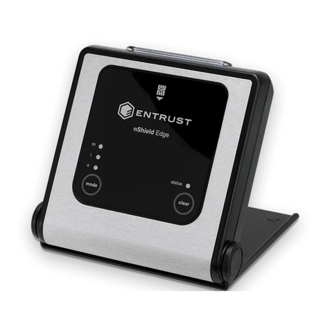
Entrust Sigma DS4 User manual

November 2021
528265-001, Rev A
User Guide
Rear Indent Module (RIM)

ii
Notice
Please do not attempt to operate or repair this equipment without adequate
training. Any use, operation or repair you perform that is not in accordance
with the information contained in this documentation is at your own risk.
Trademark Acknowledgments
Entrust, Sigma and the hexagon design are trademarks, registered trademarks
and/or service marks of the Entrust Corporation in the United States and other
countries.
Datacard is a registered trademark and service mark of Entrust Corporation in
the United States and other countries.
MasterCard is a registered trademark of MasterCard International Incorporated.
Visa is a registered trademark of Visa International Service Association.
All other product names are the property of their respective owners.
Proprietary Notice
The design and information contained in these materials are protected by US
and international copyright laws.
All drawings and information herein are the property of Entrust Corporation. All
unauthorized use and reproduction is prohibited.
Entrust Corporation
1187 Park Place
Minneapolis, MN 55379
Phone: 952-933-1223
Fax: 952-933-7971
www.entrust.com
© 2021 Entrust Corporation. All rights reserved.

iii
Safety
The following basic safety tips are given to ensure safe installation, operation and maintenance of
Datacard® equipment.
• Connect equipment to a grounded power source. Do not defeat or bypass the ground lead.
• Place the equipment on a stable surface (table) and ensure floors in the work area are dry and
non-slip.
• Know the location of equipment branch circuit interrupters or circuit breakers and how to turn
them on and off in case of emergency.
• Know the location of fire extinguishers and how to use them. ABC type extinguishers may be
used on electrical fires.
• Know local procedures for first aid and emergency assistance at the customer facility.
• Use adequate lighting at the equipment location.
• Maintain the recommended temperature and humidity range in the equipment area.
Safe Human Interface
• Use proper lifting techniques when moving or installing the equipment.
• Use standard electrostatic discharge (ESD) precautions when working on or near electrical
circuits.
• Do not defeat or disconnect safety interlocks on covers.
Liability
The WARNING and CAUTION labels have been placed on the equipment for your safety. Please do
not attempt to operate or repair this equipment without adequate training. Any use, operation,
or repair in contravention of this document is at your own risk.
California Prop
Warning: This product contains chemicals, including lead, known to the State of California to
cause cancer, and birth defects or other reproductive harm. Wash hands after handling.
For more information on this warning, refer to:
www.datacard.com/califpropwarning.
Warning: To avoid a possible electric shock, always unplug the system before servicing.

iv

v
Revision Log
Revision Date Description of Changes
A November 2021 First release of this document

vi

vii
Contents
Chapter 1: Introduction. . . . . . . . . . . . . . . . . . . . . . . . . . . . . . . . . . . . . . . . . . . . . . . . . . . . . 1
About this Manual. . . . . . . . . . . . . . . . . . . . . . . . . . . . . . . . . . . . . . . . . . . . . . . . . . . . . . . . . . . . . . 1
Intended Audience . . . . . . . . . . . . . . . . . . . . . . . . . . . . . . . . . . . . . . . . . . . . . . . . . . . . . . . . . . . . 1
Technical Support . . . . . . . . . . . . . . . . . . . . . . . . . . . . . . . . . . . . . . . . . . . . . . . . . . . . . . . . . . . . . . 1
Chapter 2: About the Rear Indent Module (RIM) . . . . . . . . . . . . . . . . . . . . . . . . . . . . . . . . 3
The Rear Indent Module . . . . . . . . . . . . . . . . . . . . . . . . . . . . . . . . . . . . . . . . . . . . . . . . . . . . . . . . . 3
Site Requirements . . . . . . . . . . . . . . . . . . . . . . . . . . . . . . . . . . . . . . . . . . . . . . . . . . . . . . . . . . . . . . 4
System Dimensions. . . . . . . . . . . . . . . . . . . . . . . . . . . . . . . . . . . . . . . . . . . . . . . . . . . . . . . . . . . 4
Rear Indent Module (RIM) . . . . . . . . . . . . . . . . . . . . . . . . . . . . . . . . . . . . . . . . . . . . . . . . . 4
RIM with Sigma DS4 Instant Financial Issuance System . . . . . . . . . . . . . . . . . . . . . . . . . 4
Clearance Requirements . . . . . . . . . . . . . . . . . . . . . . . . . . . . . . . . . . . . . . . . . . . . . . . . . . . . . 5
Sigma DS4 Instant Financial Issuance System . . . . . . . . . . . . . . . . . . . . . . . . . . . . . . . . . 5
About the Rear Indent Module . . . . . . . . . . . . . . . . . . . . . . . . . . . . . . . . . . . . . . . . . . . . . . . . . . . 6
Back and Left Side. . . . . . . . . . . . . . . . . . . . . . . . . . . . . . . . . . . . . . . . . . . . . . . . . . . . . . . . . . . 6
RIM Status Light . . . . . . . . . . . . . . . . . . . . . . . . . . . . . . . . . . . . . . . . . . . . . . . . . . . . . . . . . . . . . 7
Right Side . . . . . . . . . . . . . . . . . . . . . . . . . . . . . . . . . . . . . . . . . . . . . . . . . . . . . . . . . . . . . . . . . . 7
Front and Inside . . . . . . . . . . . . . . . . . . . . . . . . . . . . . . . . . . . . . . . . . . . . . . . . . . . . . . . . . . . . . 8
Load the Indent Ribbon Cassette . . . . . . . . . . . . . . . . . . . . . . . . . . . . . . . . . . . . . . . . . . . . . . . . 10
Card Design. . . . . . . . . . . . . . . . . . . . . . . . . . . . . . . . . . . . . . . . . . . . . . . . . . . . . . . . . . . . . . . . . . 12
Verify Setup . . . . . . . . . . . . . . . . . . . . . . . . . . . . . . . . . . . . . . . . . . . . . . . . . . . . . . . . . . . . . . . . . . 12
Chapter 3: Troubleshooting . . . . . . . . . . . . . . . . . . . . . . . . . . . . . . . . . . . . . . . . . . . . . . . . 13
Clear a Rear Indent Module Card Jam . . . . . . . . . . . . . . . . . . . . . . . . . . . . . . . . . . . . . . . . . . . 13
Repair a Broken Indent Ribbon . . . . . . . . . . . . . . . . . . . . . . . . . . . . . . . . . . . . . . . . . . . . . . . . . . 15
RIM Messages on the Printer LCD Panel . . . . . . . . . . . . . . . . . . . . . . . . . . . . . . . . . . . . . . . . . . . 16
247: Rear module error . . . . . . . . . . . . . . . . . . . . . . . . . . . . . . . . . . . . . . . . . . . . . . . . . . . . . . 16
301: RIM not detected . . . . . . . . . . . . . . . . . . . . . . . . . . . . . . . . . . . . . . . . . . . . . . . . . . . . . . 17
302: RIM arm error . . . . . . . . . . . . . . . . . . . . . . . . . . . . . . . . . . . . . . . . . . . . . . . . . . . . . . . . . . 17
303: RIM wheel error . . . . . . . . . . . . . . . . . . . . . . . . . . . . . . . . . . . . . . . . . . . . . . . . . . . . . . . . 17
304: RIM supply error . . . . . . . . . . . . . . . . . . . . . . . . . . . . . . . . . . . . . . . . . . . . . . . . . . . . . . . . 18
305: RIM lost card. . . . . . . . . . . . . . . . . . . . . . . . . . . . . . . . . . . . . . . . . . . . . . . . . . . . . . . . . . . 18
306: RIM card jam . . . . . . . . . . . . . . . . . . . . . . . . . . . . . . . . . . . . . . . . . . . . . . . . . . . . . . . . . . 19
307: RIM rear pick error . . . . . . . . . . . . . . . . . . . . . . . . . . . . . . . . . . . . . . . . . . . . . . . . . . . . . . 19
308: RIM dispense error . . . . . . . . . . . . . . . . . . . . . . . . . . . . . . . . . . . . . . . . . . . . . . . . . . . . . . 19
309: RIM error . . . . . . . . . . . . . . . . . . . . . . . . . . . . . . . . . . . . . . . . . . . . . . . . . . . . . . . . . . . . . . 19
322: RIM door open . . . . . . . . . . . . . . . . . . . . . . . . . . . . . . . . . . . . . . . . . . . . . . . . . . . . . . . . . 19

viii
Chapter 4: Supplies and Parts. . . . . . . . . . . . . . . . . . . . . . . . . . . . . . . . . . . . . . . . . . . . . . . 21
Indent Ribbon Cassette . . . . . . . . . . . . . . . . . . . . . . . . . . . . . . . . . . . . . . . . . . . . . . . . . . . . . . . . 21
Storage Guidelines. . . . . . . . . . . . . . . . . . . . . . . . . . . . . . . . . . . . . . . . . . . . . . . . . . . . . . . . . . 21
Power Supplies. . . . . . . . . . . . . . . . . . . . . . . . . . . . . . . . . . . . . . . . . . . . . . . . . . . . . . . . . . . . . . . . 22
Power Cords. . . . . . . . . . . . . . . . . . . . . . . . . . . . . . . . . . . . . . . . . . . . . . . . . . . . . . . . . . . . . . . . . . 22

1
Rear Indent Module User’s Guide 1
Chapter 1: Introduction
About this Manual
This manual provides user information for the Rear Indent Module (RIM). The manual includes:
An overview of the module, and a description of the system label.
How to load and replace supplies.
How to perform routine maintenance and troubleshooting tasks.
Refer to the printer’s user documentation for information about setting up and using the printer.
Intended Audience
The manual is intended for the printer operator who prints cards, loads and replaces supplies,
maintains the printer, and performs troubleshooting.
Technical Support
Use the following to contact Entrust Technical Phone Support.
Americas +1 800.328.3996 or
+1 952.988.2316
EMEA (Europe, Middle East, Africa) +44 1489555627
Asia Pacific +852 2821 0126

2 Introduction

2
Rear Indent Module User’s Guide 3
Chapter 2: About the Rear
Indent Module (RIM)
This guide provides information about the optional Rear Indent Module
(RIM) that you can add to your system at the time of purchase or later,
as a field upgrade.
The Rear Indent Module
The RIM can be added to the back of a Sigma DS4 Instant Financial Issuance System. It allows you
to place indent characters on the front or back of the card. The RIM uses an indent character
wheel and an ink ribbon to indent numbers below the surface of the card.
Sigma DS4 Instant Financial Issuance System requires D4.2.1 firmware or higher for RIM
compatibility.
Contact you system administrator for details on printer firmware.
RIM
Sigma DS4 Card Printer

4 About the Rear Indent Module (RIM)
Site Requirements
Provide space for the system and for clearance around the system.
System Dimensions
The external system dimensions are shown in the following illustrations.
Rear Indent Module (RIM)
RIM with Sigma DS4 Instant Financial Issuance System
9.5 in
241 mm
8.7 in
221 mm
8.35 in
212 mm
8.9 in
226 mm
9.0 in
229 mm
9.5 in
241 mm
26.1 in
663 mm

Rear Indent Module User’s Guide 5
Clearance Requirements
The following measurements show the system dimensions when the printer input hopper,
printer cover, and RIM access door are open.
Sigma DS4 Instant Financial Issuance System
Best practices recommend that you provide a minimum of 3 inches (76.2 mm) of
additional clearance around the sides and rear of the system to maintain access to
the power cords and data cables, to load and remove cards and supplies, and to
provide ventilation.
17.5 in
444 mm
10.9 in
277 mm
6.4 in
163 mm
15.3 in
389 mm
29 in
737 mm

6 About the Rear Indent Module (RIM)
Electrical Requirements
The power supply detects the input voltage and works within the range stated.
About the Rear Indent Module
Use the following information to become familiar with the RIM.
Back and Left Side
Electrical Requirements
Input Output
100–240V/50–60 Hz/1.6Amp 24V/3.0Amp/72W
The RIM power supply is separate from the printer power supply.
Refer to your printer’s Installation and Administrator’s Guide for printer electrical
requirements.
RIM Status Light The light shows the status of the RIM. Refer to “RIM Status
Light” on page 7.
Rear Exit The rear exit allows a card to be moved out of the rear
indent module, for example to clear a card jam.
Note: The card also moves a short distance out the rear exit
while indenting.
Power Connection The power connection provides a plug-in connector for the
RIM power supply.
Rear Exit
RIM Status Light
Power Connection

Rear Indent Module User’s Guide 7
RIM Status Light
The status light shows the status of the RIM:
Right Side
Ready Solid green
Busy Blinking green
Idle/Not ready Solid blue
Error Blinking red
Lost communication
with printer
Solid red
Door Lock The door lock secures access to interior of the RIM.
Door Lock

8 About the Rear Indent Module (RIM)
Front and Inside
Access Door The access door provides access to RIM supply cassette and
connection latch.
RIM Supply Cassette The supply cassette holds the indent ribbon.
Adapter Plate The adapter plate allows the RIM to fit against the printer.
Note: The adapter plate may differ from the illustrations in
this guide, depending on the printer model. Any differences in
procedures are described, as needed.
Connection Guideposts The guideposts connect the RIM to the printer.
Rear Module Data
Connection
The electrical connection for the rear indent module to
connect to the printer.
Note: Avoid touching or jarring the electrical connection.
Damage to the RIM can occur.
Drive Gear The drive gear allows you to move a card out of the RIM if a
card jam occurs. Refer to “Clear a Rear Indent Module Card
Jam” on page 13.
Connection Latch Secures the RIM to the printer.
Access Door
RIM Supply
Cassette
Connection
Guideposts
Drive Gear
Rear Module
Data Connection
Connection
Latch
Adapter Plate

Rear Indent Module User’s Guide 9
RIM Configuration Label
The RIM configuration label is located inside the RIM on
the access door.
The configuration label shows the following information:
Module name
Serial number
Configuration
Part number
Date
Option Configuration Code
Ribbon Drive R1=Indent Ribbon Required
Wheel Option W1=Reverse Italic, Standard Orientation
W3=Helvetica, Standard Orientation
Adapter Plate A2=Sigma Printer
Lock Option L1=Rear Module Lock
Configuration Label

10 About the Rear Indent Module (RIM)
Load the Indent Ribbon Cassette
1. Press the power button to power down the printer.
2. Unlock the RIM and open the side access door.
3. Remove the supply cassette from the shipping bag and position
the cassette as shown.
4. Turn the left spool clockwise to remove any slack in the supply.
Look into the cassette to ensure that the slack is removed from
both spools and the ribbon.
5. Position and push in the supply cassette as shown to install it into
the RIM.
The RIM ribbon cassette installed. Message 304, RIM supply out, displays on the
printer LCD if a cassette is not installed.
The ribbon cassette contains a one-time-use roll of indent ribbon.
Make sure the ribbon is installed under the anvil feature located beneath the supply
posts.
Cassette Front
Anvil
Anvil
Supply
Cassette
Ribbon

Rear Indent Module User’s Guide 11
6. Close the side access door and lock the RIM.
Make sure the supply cassette is secured under the clip when installed.
Supply
Cassette
Clip

12 About the Rear Indent Module (RIM)
Card Design
Set up your card design using your card production software or another application, such as
Microsoft Word.
Standard indent position is on the right half of the card (starts 1.8" from left side of card).
The RIM can indent characters on either the front or back of the card.
You can fine-tune the settings that control the RIM using Printer Dashboard. Refer to the Printer
Dashboard Help for information about using Printer Dashboard.
Verify Setup
After you set up the indent preferences, print several test cards to determine if the settings meet
your requirements.
When evaluating a card, make sure that:
The indent characters are positioned correctly and have the proper depth.
The indent characters are applied correctly. Look for voids, or faint lines in the indent
characters.
The indent module does not support indenting a card that previously has been
laminated using the CLM laminator.
Standard Indent
Position
Other manuals for Sigma DS4
5
Table of contents
Other Entrust Control Unit manuals
Popular Control Unit manuals by other brands

PNI
PNI Prime Pro user manual

Emerson
Emerson SAPAG CLASAR Series Technical description, installation, operating and maintenance instructions

Daikin
Daikin E2MV03B6 Original instructions

Burkert
Burkert 8631 operating instructions

Tektronix
Tektronix 7B70 instruction manual

Siemens
Siemens Synco RMZ792 Basic documentation

VTI
VTI SCP1000 user manual

ITRON
ITRON OpenWay Riva 500G installation guide

National Instruments
National Instruments NI 9514 Operating instructions and specifications

Nordson
Nordson Auto-Flo II Customer product manual

Emerson
Emerson SI-PROFIBUS user guide

Holybro
Holybro Micro OSD V2 Full Manual & Installation Guide