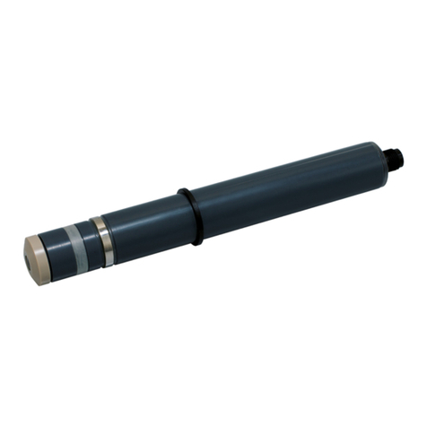
Sea-Bird Scientific WQM-a User manual

User manual
WQM
Water Quality Monitor
Document No. WQM/x171031
Release Date: 2018-07-26
Version: A
541-929-5650
seabird.com


Table of Contents
Section 1 Specifications.................................................................................................................... 3
1.1 Mechanical................................................................................................................................... 3
1.1.1 Standard bulkhead connector............................................................................................. 3
1.1.1.1 Serial connector......................................................................................................... 3
1.1.1.2 Analog external data port connector.......................................................................... 3
1.2 Electrical....................................................................................................................................... 4
1.3 Communications.......................................................................................................................... 4
1.4 Optical.......................................................................................................................................... 4
1.5 Conductivity, Temperature, Depth, Dissolved Oxygen................................................................ 4
Section 2 Functional check.............................................................................................................. 5
2.1 Pre-deployment check................................................................................................................. 5
2.2 Monitor data................................................................................................................................. 6
2.2.1 Scroll data tab..................................................................................................................... 7
2.2.2 Data sidebar area................................................................................................................ 7
2.2.3 View data tab.......................................................................................................................8
2.3 Stop sensor.................................................................................................................................. 8
Section 3 Sensor set up and operation..........................................................................................9
3.1 Pre-deployment tasks.................................................................................................................. 9
3.1.1 Adjust BLIS calculator......................................................................................................... 9
3.1.2 Adjust power failure message............................................................................................. 9
3.1.3 Adjust data file number........................................................................................................9
3.1.4 Adjust pressure offset........................................................................................................10
3.2 Set up sensor for deployment.................................................................................................... 10
3.2.1 Adjust operation setup.......................................................................................................11
3.3 Set up data output...................................................................................................................... 12
3.4 External data port (EDP)............................................................................................................ 12
3.4.1 Digital EDP setup.............................................................................................................. 13
3.4.2 Analog EDP setup............................................................................................................. 13
3.4.3 Custom EDP set up........................................................................................................... 14
3.4.4 Erase EDP setup............................................................................................................... 16
3.5 Monitor data collection............................................................................................................... 16
3.6 Save data................................................................................................................................... 16
3.6.1 File types........................................................................................................................... 17
3.7 Erase data.................................................................................................................................. 17
3.8 Set up BLIS for deployment....................................................................................................... 18
Section 4 Sensor maintenance...................................................................................................... 21
4.1 CT-DO maintenance.................................................................................................................. 21
4.2 Replace CT-DO anti-fouling devices.......................................................................................... 22
4.2.1 Replace CT-DO intake anti-fouling cartridge.....................................................................23
4.2.2 Replace CT-DO exhaust anti-fouling cartridge..................................................................24
4.3 Clean ECO sensors................................................................................................................... 25
4.3.1 Clean Bio-wiper and faceplate.......................................................................................... 25
4.3.2 Wiper replacement............................................................................................................ 27
4.4 Examine pressure sensor.......................................................................................................... 28
4.5 Examine and maintain BLIS...................................................................................................... 28
4.5.1 Verify flow volume of BLIS................................................................................................ 29
4.5.2 Troubleshoot BLIS.............................................................................................................31
4.6 Maintain bulkhead connector..................................................................................................... 31
4.7 Long term storage...................................................................................................................... 32
Section 5 Reference..........................................................................................................................33
1

5.1 Setup selections......................................................................................................................... 33
5.1.1 Date and time.................................................................................................................... 33
5.1.2 Get and send setup information........................................................................................ 33
5.1.3 Dissolved Oxygen (DO) stabilization time......................................................................... 33
5.1.4 Bleach Injection System (BLIS) operation........................................................................ 33
5.1.5 Power use estimates......................................................................................................... 34
5.1.6 Sensor internal disk storage.............................................................................................. 34
5.1.7 User-specific internal sensor characterization...................................................................35
5.1.8 Uninterruptible Power Supply (UPS)................................................................................ 35
5.1.9 Autonomous sample control.............................................................................................. 36
5.1.10 External sample control................................................................................................... 37
5.2 Data collection............................................................................................................................ 37
5.3 Data display............................................................................................................................... 38
5.4 Data storage............................................................................................................................... 38
5.5 Power modes............................................................................................................................. 39
5.6 Missing data............................................................................................................................... 40
5.7 Digital pH sensor (SBE-18S) setup............................................................................................ 40
5.7.1 Connect a pH sensor.........................................................................................................40
5.8 Advanced file processing........................................................................................................... 41
5.9 Functional tests.......................................................................................................................... 42
5.10 Horizontal deployment............................................................................................................. 43
5.11 Bio-fouling prevention.............................................................................................................. 44
5.12 Spare parts............................................................................................................................... 44
5.13 Bleach Injection System (BLIS) operation............................................................................... 45
Section 6 General information....................................................................................................... 47
6.1 AF24173 anti-fouling device....................................................................................................... 48
6.2 Warranty..................................................................................................................................... 49
6.3 Service and support................................................................................................................... 50
6.4 Waste electrical and electronic equipment................................................................................. 50
Table of Contents
2

Section 1 Specifications
1.1 Mechanical
Diameter 18.5 cm
WQM length 65.4 cm
WQMx length 69.0 cm
Depth rating 200 m
Temperature range -5–35 °C
Pressure housing Acetal coploymer, ABS, PVC, titanium, copper
WQM weight in air, water 5.4 kg, 1.8 kg
WQMx weight in air, water 6.25 kg, 1.7 kg
1.1.1 Standard bulkhead connector
Contact Function MCBH-6-MP connector
1 Ground
2 RS232 RX
3 Reserved
4 Voltage in
5 RS232 TX
6 Reserved
1.1.1.1 Serial connector
Contact Function MCBH-4-FS connector
1 Ground
2 Voltage in
3 RS232 RX
4 RS232 TX
1.1.1.2 Analog external data port connector
Contact Function MCBH-6-FS connector
1 analog 2 analog
1 Ground
2 Analog 1
3 Analog 1 ground
4 Voltage in
5 No connect Analog 2
6 No connect Analog 2
3

1.2 Electrical
Input voltage 9–16 VDC
Current draw, data collection < 100 mA
Current draw, peak data collection 180 mA
Current draw, BLIS operation 350 mA
Current draw, low power < 50 µA
1.3 Communications
Transfer standard RS232
Sample rate 1 Hz
1.4 Optical
Sensor Parameter Wavelength Range, Sensitivity
WQM, WQMx Chlorophyll 470/695 nm 0–30, 0.015 µg/L
WQM Turbidity 700 nm 0–25, 0.013 NTU
WQMx CDOM 370/460 nm 0–375, 0.18 ppb
WQMx Scattering 700 nm 0–3, 0.002 m-1
1.5 Conductivity, Temperature, Depth, Dissolved Oxygen
Parameter Range Accuracy Resolution
Conductivity 0–9 S/m 0.0003 S/m 0.0005 S/m
Temperature -5–35 °C 0.002 °C 0.001 °C
Depth (Pressure) 1–100 or –200 m 0.1% full scale 0.002% full scale
Dissolved Oxygen 120% of saturation
(150% on request)
2% of saturation 0.035% of saturation
0.003 ml/L at 0 °C, 35 PSU
Specifications
4

Section 2 Functional check
WARNING
FDOM sensors use an ultraviolet LED light source. Do not look directly at a UV LED when it is on.
It can damage the eyes. Keep products that have UV LEDs away from children, pets, and other
living organisms. Wear polycarbonate UV-resistant safety glasses to protect the eyes when a UV
LED is on.
The WQM has configurations of sensors that use the abbreviations listed below.
• WQM—Water Quality Monitor
• BLIS—BLeach Injection System
• CTD—Conductivity, Temperature, Depth
• DO—Dissolved Oxygen
• FDOM—Fluorescent Dissolved Organic Matter
Model Description
WQM-a Available analog output. BLIS anti-fouling. Chlorophyll fluorometer and turbidity sensor. CTD and DO sensors.
WQM-d Digital output. BLIS anti-fouling. Chlorophyll fluorometer and turbidity sensor. CTD and DO sensors.
WQMx-a Available analog output. BLIS anti-fouling. Chlorophyll fluorometer, turbidity, and CDOM sensors. CTD and DO
sensors.
WQMx-d Digital output. BLIS anti-fouling. Chlorophyll fluorometer, turbidity, and CDOM sensors. CTD and DO sensors.
2.1 Pre-deployment check
The user needs the items listed below to make sure that the sensor operates correctly
before deployment.
• a clean work bench
• a PC
• a regulated power supply
Manufacturer-supplied:
• test cable
• sensor
• CD with software
• 5/32" hex key
• orange fluorescent stick
• blue fluorescent stick
1. Lubricate each of the connectors with pure silicone spray. Let the spray dry. Refer to
the section on "bulkhead connector maintenance" for details about how to care for
bulkhead connectors.
2. Select the software, the file on the CD that ends with ".exe" and move it to the
desktop of the PC.
The software is now available on the PC.
3. Connect the test cable to the PC, the sensor, and the power supply.
4. Start the software on the PC.
5. Supply power to the sensor.
The software tries to identify the COM port and the baud rate.
6. If necessary, select the COM port and the baud rate (19200) from the drop-down
menu in the COM Port Setup area of the software.
5

7. Push Start Sample, then push Start WQM Now.
The sensor does a warm-up for the CTD, DO, and the optics before it starts the
Sample mode. This sequence takes approximately 35 seconds.
8. Push Stop WQM Sample, then push Yes, Stop WQM Sampling.
The sensor goes into In Standby mode. The user can now make changes to the
sensor setup.
9. Go to the WQM Setup tab.
10. Push Set Date and Time to make sure the PC and the sensor show the same date
and time.
11. Go to The WQM Output tab.
12. Make sure to select the boxes listed below:
a. Conductivity
b. Temperature
c. Pressure
d. Raw dissolved oxygen
e. Processed dissolved oxygen
f. Chlorophyll
g. NTU
h. FDOM (WQMx only)
Only those values with selected boxes are stored by the sensor as data. A data value
with a box that is not selected is not available in the Data Sidebar area or the View
Data tab.
13. Push Send Output Configuration.
The selected parameters are stored in the sensor.
14. Push Start WQM Sample.
The sensor starts its warm-up cycle.
2.2 Monitor data
There are three places in the software to monitor the data collected by the sensor.
• The Scroll Data tab.
• The View Data tab.
• The Data Sidebar area.
1. Look at the data in the Data Sidebar area.
2. Change the values of the collected data:
• For chlorophyll: Put an orange fluorescent stick in front of the chlorophyll (blue)
light to change the value of the data from the chlorophyll sensor. The value
increases toward the maximum output value listed on the sensor's
characterization page.
• For NTU: Put a solid object such as a finger in front of the turbidity (red) light to
change the value of the data from the turbidity sensor. The value increases
toward the maximum output value listed on the sensor's characterization page.
Functional check
6

• For FDOM: Put a blue fluorescent stick in front of the FDOM (purple) light to
change the value of the data from the FDOM sensor. The value increases toward
the maximum output value listed on the sensor's characterization page.
3. Make sure that the CTD and DO sensor have the output values as listed below.
• Conductivity: 0.000 (+0.0005, -0.0001)
• Temperature: current room temperature
• Pressure: 0.00 (±0.5)
• Raw Dissolved Oxygen: 3000–15000 Hz
• Processed Dissolved Oxygen: 3–6.5 ml/L
2.2.1 Scroll data tab
The Scroll Data tab shows the data collection, the sensor's status records, and other
miscellaneous messages. Sensors that use version 1.5 or newer show data collection at
1 Hz. Older versions show the data collected once every 10 seconds when the sensor is
in air, and at 1 Hz when it is in water.
1. Go to the Scroll Data tab.
2. Monitor the collected data.
•WETS_ ...: These lines show the sensor's serial number and the conditions that
are used by the sensor in the setup and view controls.
•WQM,SN,Date(mmddyy),...:These lines show the column headings for the
collected data.
•WQM,1001,0207013,...: These lines show data records. These records are
transmitted at 1 Hz when the sensor collects data.
2.2.2 Data sidebar area
The Data Sidebar area shows the data and lets the user select the parameters that show
in the graph area of the View Data tab.
1. Look at the Data Sidebar area on the left side of the software window to see which
parameters will show on the graph in the View Data tab.
Functional check
7

Temperature, Pressure, DO, Turbidity, Chlorophyll and CDOM show in the View Data
tab.
2. Select different checkboxes under the Plot heading to see different parameters in the
View Data tab.
3. Start the sensor.
4. Monitor the data in the View Data tab and in the Data Sidebar area.
2.2.3 View data tab
Monitor the collected data in real-time.
1. Go to the View Data tab.
2. The user can change the parameters that show in the plot area of View Data tab.
a. Put the sensor in In Standby.
b. Go to the WQMx Output tab.
c. Select the check boxes for the parameters to be stored in the sensor.
d. Push Send Output Configuration.
e. Go to the Data Sidebar area and select the parameters to show in the View Data
graph area.
2.3 Stop sensor
Stop the sensor to finish the functional check.
1. Push Stop WQM Sample.
a. No more data is collected on the View Data and Scroll Data tabs, or the Data
Sidebar area.
b. The Bio-wiper closes on the WQM. The wiper does not move on the WQMx.
c. The Scroll Data tab shows "status records" that start with "WETS" at 1 Hz.
d. The sensor is in In Standby.
2. Turn off the power supply.
3. Disconnect the sensor from the power supply and the PC.
Functional check
8

Section 3 Sensor set up and operation
WARNING
Bleach is caustic. Wear nitrile gloves and safety glasses and work in a well ventilated area to use
bleach.
CAUTION
Do not supply more than 16 VDC to the sensor. More than 16 VDC will cause damage.
NOTICE
Make sure that the BLIS system has fresh bleach, and that the software is set up for the
environment in which the sensor will be deployed.
3.1 Pre-deployment tasks
Make sure that the values for the BLIS, the sensor power, the data files and the pressure
sensor are set up correctly before each deployment.
1. Start the software if necessary.
2. Make sure the sensor has power supplied and is in In Standby.
Refer to Pre-deployment check on page 5 for details.
3. If necessary, clear the red background in the clock area. Go to the WQM Output tab
and push Set Date and Time.
The time shown on the sensor's clock and on the PC clock are the same.
4. Go to the Pre-deployment menu at the top of the software window.
3.1.1 Adjust BLIS calculator
The software counts the number and the volume of bleach squirts and calculates the
quantity of the bleach used during a deployment. Make sure that the bleach reservoir is
emptied and then filled with 150 mL of 5% fresh bleach before every deployment.
1. Go to the Pre-Deployment menu, then select Clear BLIS Volume Used.
2. In the window that opens, push OK to set the volume of bleach that has been used to
0.00 mL.
3. Go to the WQM Setup tab and push Send New Setup.
The "BLIS Volume Used" shows 0.00.
3.1.2 Adjust power failure message
If the supplied voltage falls too low or power is lost, the Uninterruptible Power Supply
(UPS) comes on. The software shows the condition in red.
Select the "Clear Power Failure Message" to adjust this in the software.
• The UPS message goes out of view.
3.1.3 Adjust data file number
Note: This is used in External Control mode only.
In External Control mode, the file numbers do not change. This is so that all of the data
in a deployment is collected in the same file.
1. View the "File #."
9

2. Push Increment File # to make the file number increase.
3. Push Get Status.
The file number increases by one.
3.1.4 Adjust pressure offset
The sensor uses pressure measurements to calculate the depth of the water. As the
atmospheric pressure changes, the sensor calculates an offset for the pressure
measurement. Set the pressure measurement to 0.00 dbar before a deployment.
1. Select the Pre-Deployment menu.
2. Select the Reset Pressure Offset menu item.
3. Do the steps in the new window.
a. Put the sensor just above the surface of the water near the location of the
planned deployment.
b. Supply power to the sensor.
c. Put the sensor in In Standby.
d. Push OK in the Reset the WQM Pressure Offset window.
4. Wait for approximately 2 minutes for the sensor to adjust to the atmospheric pressure
and altitude.
5. The message "Pressure Reset Completed" shows in the Scroll Data tab.
The sensor goes into In Standby.
6. Remove the power to the sensor.
7. Start the sensor again to make sure that the pressure measurement is
0.00 ±0.01 dbar.
8. Stop the sensor.
9. Remove the power to the sensor.
3.2 Set up sensor for deployment
Use the WQMx Setup tab to look at or adjust the parameters that the sensor uses to
operate. These include:
• the current time
• the data collected
• the condition of the BLIS
• the condition of the data files
• the condition of the power supply.
1. If necessary, start the software.
2. If necessary, supply power to the sensor.
3. Put the sensor in In Standby.
Sensor set up and operation
10

Refer to the section on Pre-deployment check on page 5 for details.
4. Push Get Current Setup.
Look at the values stored in the sensor. They show in the Current Setup area.
3.2.1 Adjust operation setup
The examples in this section refer to a sensor that is set up for "Autonomous" operation.
Refer to the section on External sample control on page 37 for instructions on how to
set up the sensor for External Sample Control.
1. View the values in the 'New Setup' Power Consumption area of the software.
1 The number of hours, minutes or seconds that the sensor
actively collects data.
4 The number of days that the sensor will be deployed.
2 The time each "Sample For" in #1 is set to, plus the time
in low-power and warm-up.
5 The volume of the bleach solution that is used for each
injection.
3 The minimum expected temperature in the water where
the sensor is to be deployed.
2. Adjust the values to see how the Estimated Power Consumption @ 12 V and the Est.
BLIS Remaining are affected.
3. Adjust these values for the next deployment.
Sensor set up and operation
11

4. Push Send New Setup to store the values in the sensor.
5. Push Get Current Setup to make sure that the correct values show.
3.3 Set up data output
1. Make sure that power is supplied to the sensor and it is in In Standby mode.
2. Go to the WQM Output tab.
3. Push Get Output Configuration.
Look at the parameters stored in the sensor.
4. Look at the parameters that have checkmarks in the boxes next to them.
5. Make the selections for the next deployment.
These parameters will show in the Scroll Data tab.
Note: Either the Raw ECO or the ECO always has a checkmark.
6. Push Send Output Configuration to store the selections in the sensor.
These parameters will show in the Scroll Data tab when the data is being collected.
Note: Either the Raw ECO or the ECO always has a checkmark.
3.4 External data port (EDP)
All WQM sensors have two bulkhead connectors so that the user can connect an external
sensor to the WQM. Either a digital (4-socket) or an analog (6-socket) connection is
available.
Digital connections:
• CDOM
• PAR
• SBE18S pH
• Custom Setup
Analog connections:
• Analog 1
• Analog 1 + 2
• SBE18 pH
• SBE27 pH and redox
1. Go to the Advanced menu at the top of the software screen and select Setup
External Data Port.
Sensor set up and operation
12

A new tab, External Data Port, shows in the software.
2. Push Get EDP Setup from WQM.
Look at the setup values stored in the sensor.
3.4.1 Digital EDP setup
The user can adjust the "Signal" values in this tab so that the latest characterization
values from a connected sensor are stored in the WQM. Refer to the Custom EDP set up
on page 14 to connect a digital sensor that is not listed in the drop-down menu.
1. Make sure that the external digital sensor is connected to the WQM sensor.
2. Make sure that the sensor is in In Standby.
3. Push Get EDP Setup from WQM.
The manufacturer sets up the calibration or characterization values that are specific
to an external sensor and these will show in the External Data Port Setup tab.
4. If no sensor has been set up, go to the Instrument Options drop-down menu and
select the sensor that is connected to the WQM.
5. Make sure that the values on the sensor-specific calibration page for the sensor
agree with the information in the Signal 1 area.
6. To change the calibration or characterization values, push Edit in the Signal 1 area.
The values are the same as the calibration or characterization page, or the most
recent application-specific characterization that the user did.
7. Push Done in the Signal 1 area.
8. Push Send New Setup.
The calibration or characterization values for the external sensor are stored in the
WQM.
3.4.2 Analog EDP setup
1. Make sure that the external analog sensor is connected to the WQM sensor.
2. Make sure that the sensor is in In Standby.
3. Select the Advanced menu, then Setup Analog.
4. If no sensor is selected, select the analog sensor that is connected to the WQM from
the Instrument Options drop-down menu.
An example setup for an SBE27 is shown below.
Sensor set up and operation
13

5. Enter the serial number of the analog sensor in the SN: text box.
6. Push Edit to change the pH Slope or pH Offset in the Analog Signal 1 area.
7. Push Done.
8. Push Edit to change the ORP M or ORP B in the Analog Signal 2 area.
9. Push Done.
10. Push Send New Setup.
The Status area will show "Loading..." until the new setup is stored in the sensor.
11. Push Done/Close Tab.
12. Push Stop WQM Sample, then Yes, Stop WQM Sampling.
13. Remove power to the WQM.
The sensor is ready to be deployed.
3.4.3 Custom EDP set up
Use the "Custom Setup" function to set up sensors that can collect more than a single
"Signal" or parameter of data.
1. Make sure that the external sensor is connected to the WQM.
2. Make sure that the WQM sensor is in In Standby.
3. Go to the External Data Port tab.
4. Push Get EDP Setup from WQM.
The stored setup values will show in the window. If custom setup values do not show,
the user needs to enter them.
5. Select "Custom Setup" in the Instrument Options drop-down menu.
6. Do the procedures below to set up a three-parameter ECO sensor as in the example.
The user needs the sensor's device file to complete the setup.
Sensor set up and operation
14

a. Select the serial number ("SN") of the sensor connected to the WQM.
b. Select the number of sampling parameters ("Signals") the sensor has.
c. Select the "Total Columns" of output.
The software counts the S/N, Date, Time as columns 1–3. The data format of the
external sensor is N/U, Data, N/U, Data, N/U, Data, N/U where N/U is "not used"
and the data ("Signal") as the WQM host calculates it is in columns 4, 6, and 8.
d. Select "19200" for the baud rate of the sensor.
e. Select "ihm=1" for a standard ECO sensor. Or select "ihm=2" for a Triplet-w.
f. Select "iom=1" for a standard ECO sensor. Or, select "iom=2" for an ECO sensor
with a Bio-wiper. Or, select "iom=3" for a Triplet-w.
g. Select "1" for the SN Column =.
h. Select "2" for the Date Column =.
i. Select "3" for the Time Column =.
j. Select either Comma, or Tab, or Space to separate the columns of the collected
data.
7. Do the procedures below to set up each of the three signals as in the example.
8. Push Edit in the Signal 3 area.
a. Select "8" for the Column:.
b. Select "Scale'n'Offset:" for the Math:.
The Header: value is fills in automatically.
c. Enter "Counts" for the Raw Units:.
("DKFOL" means "don't know find out later")
d. Enter "µg/L," or "scattering" or other appropriate label value for the Units:.
Sensor set up and operation
15

e. Enter the Scale:, the scale factor of the sensor from the sensor-specific
calibration or characterization page.
f. Enter the Offset:, the offset (dark counts) value from the sensor-specific
calibration or characterization page.
9. Push Done.
10. Do the step above for Signal 1 and Signal 2.
11. Push Send New Setup.
Make sure that the Status area at the top of the window shows "Storing EDP Setup"
while the setup values are saved to the WQM.
12. Go to the Sample Output tab.
13. Select either or both Raw EDP 1 and EDP 1.
"Raw" is output in counts. EDP is processed output such as µg/L, NTU, scattering,
etc.
14. Press Send Output Configuration.
The Status area shows "Loading Output."
3.4.4 Erase EDP setup
Do these steps to erase the setup that is stored in the WQM sensor.
1. Make sure that the status of the WQM is In Standby.
2. Go to the Advanced menu at the top of the software window.
3. Select Setup External Data Port.
The External Data Port tab opens.
4. Under the Instrument Options drop-down menu, select "Clear EDP Setup."
5. Push Send New Setup.
The status of the WQM shows Erasing EDP Setup.
6. Turn off the power supply and disconnect the sensor that is connected to the external
data port.
7. Connect a different sensor.
8. Turn the power supply on.
The WQM does its warm-up cycle and starts to collect data.
9. Push Stop WQM Sample.
The sensor is in In Standby.
10. Go to the Advanced menu at the top of the software window.
11. Select Setup External Data Port.
12. Under the Instrument Options drop-down menu, select the sensor that is connected
to the WQM external data port.
13. Refer to the Digital EDP setup on page 13 section or the Custom EDP set up
on page 14 section to complete the set up of the sensor that is connected to the
WQM.
3.5 Monitor data collection
Monitor the data that is collected in the Scroll Data tab or the View Data tab. Use the
selections in the Data Sidebar area to monitor the data in the graph area of the View Data
tab. Refer to the section Monitor data on page 6 for details.
3.6 Save data
Go to the WQMx Files tab to save and erase data from the sensor.
Sensor set up and operation
16

1. Push Select Download Folder to select a location on the PC to save the
downloaded data.
2. Push Get WQMx Directory.
A list of the files stored in the sensor shows in the WQM Directory area.
3. Select the file or files to download to the PC. In the example above, files 005, 009 and
014 from WQMx 1001 are selected.
The user can adjust the baud rate to 115200 to increase the download speed.
4. Push Download WQMx Files.
The Download File Status shows "Complete" when the last selected file is
downloaded.
5. To stop a file or files from being downloaded, push Cancel Download.
• Software version 1.5 and newer: the file transfer will stop immediately.
• Software version 1.26 and older: the file transfer will complete for the current file,
and then stop.
3.6.1 File types
The software saves both .raw and .dat files to the PC.
• The .raw file is the data that is stored in the sensor.
• The .dat file has processed data with both raw (counts) and derived values.
To view collected data in counts only, select the box at "Download Only: No .DAT" in the
WQM Files tab.
To view the data collected in counts and as processed data, ignore the checkbox or
select Advanced File Processing. Refer to the section on Advanced file processing
on page 41 for details. Processed data is saved to the PC.
3.7 Erase data
The user can erase selected files from the sensor or format the sensor memory card.
1. Go to the WQMx Files tab.
2. Push Get WQMx Directory.
3. Select the files to erase from the directory.
4. Push Erase WQM Files.
• To erase the selected files, select Delete the Selected Files.
• To erase all of the files on the flash memory card, select Flash Format the Flash
Memory Card.
5. Push Erase.
The Status area at the top of the window shows the percentage of the selected files
that have been erased.
6. Push Done to go to the WQMx Files tab again.
Sensor set up and operation
17

3.8 Set up BLIS for deployment
DANGER
Bleach is corrosive and harmful to almost every part of the sensor. Make sure that bleach does
not get into the sensor.
The BLeach Injection System (BLIS) must be filled with bleach and its pump must be
primed before deployment. Only put bleach into a BLIS that will be deployed. If the sensor
will be put in storage, make sure there is NO bleach in the system.
Supplies:
User-supplied Manufacturer-supplied
Clean water 5/32" hex key
Container for up to 150 ml of bleach Plastic-tipped syringe (10 ml)
Household bleach Syringe with quick-disconnect attachment (3 ml)
1. Insert the long end of the 5/32" hex key straight through the hole in the copper BLIS
guard.
The key touches the reservoir release button.
2. Push firmly on the key to release the reservoir.
3. Insert the short end of the 5/32" hex key into one of the holes at the top of the
reservoir and lift the reservoir straight up and out.
Sensor set up and operation
18
This manual suits for next models
5
Table of contents
Other Sea-Bird Scientific Measuring Instrument manuals

Sea-Bird Scientific
Sea-Bird Scientific ECO-FLNTUS User manual
Sea-Bird Scientific
Sea-Bird Scientific SBE 37 MicroCAT Quick manual

Sea-Bird Scientific
Sea-Bird Scientific SBE 39plus-IM User manual

Sea-Bird Scientific
Sea-Bird Scientific SUNA V2 User manual
Sea-Bird Scientific
Sea-Bird Scientific SUNA V2 User manual
Sea-Bird Scientific
Sea-Bird Scientific SBE 11plus V2 User manual
Sea-Bird Scientific
Sea-Bird Scientific SBE 39plus User manual

Sea-Bird Scientific
Sea-Bird Scientific OCR-504 User manual
