7
MAINTENANCE
For safe and trouble-free operation of your EPIC STRENGTH strength equipment, it is important to perform
preventive maintenance on a regular basis. Make sure that all parts are properly tightened each time the strength
machine is used. Replace any worn parts immediately. The strength machine can be cleaned with a cloth damp-
ened with water and a mild, non-abrasive soap. Do not use solvents.
Note: Instruct all personnel to perform equipment inspection and maintenance requirements. Personnel must
record and report any accident. For any questions or concerns, see HOW TO CONTACT CUSTOMER CARE
on the back cover of this manual.
Use only original EPIC STRENGTH parts for repair or replacement to maintain your machine’s warranty.
FreeMotion Fitness recommends the following procedures:
SCHEDULED MAINTENANCE
DAILY
1. Upholstery—General cleaning:
•Wipe using a cloth dampened with a solution of
warm water and a mild soap.
•If necessary,use a soft bristle brush with the
cleaning solution.
•Always remove the cleaning solution using a
cloth dampened with clean water. Rinse often.
2. Upholstery—Difficult stains:
•Spray the stain with a non-abrasive household
cleaner such as FORMULA 409®cleaner,
SIMPLE GREEN®,or a similar product.
•Rub the area gently and let it sit for a few min-
utes.
•Rinse thoroughly using a cloth dampened with
clean water.
•Repeat if necessary using a soft bristle brush.
Optional method for difficult stains:
•Rub the area gently using a cloth dampened
with rubbing alcohol.
•Rinse thoroughly using a cloth dampened with
clean water to remove alcohol residue.
CAUTION: When using any cleaning product, try
it first in an inconspicuous place to ensure there
is no damage to the material. Follow directions
and adhere to safety precautions of each manu-
facturer of cleaning agent used. FreeMotion
Fitness and its vendors cannot be held liable for
damage or injuries resulting from the use or mis-
use of cleaning products.
3. Towers and Frames:
•Wipe using a cloth dampened with a solution of
warm water and a mild soap.
•Rinse and dry thoroughly.
Important: Do not use abrasive cleaners because
they may scratch the equipment. Strong cleansers
and abrasives will damage decals. Use caution
around decals. Do not use solvents such as lacquer
thinner, kerosene, gasoline, or similar liquids.
WEEKLY
1. Hardware:
•Check all nuts and bolts. Tighten them as
required.
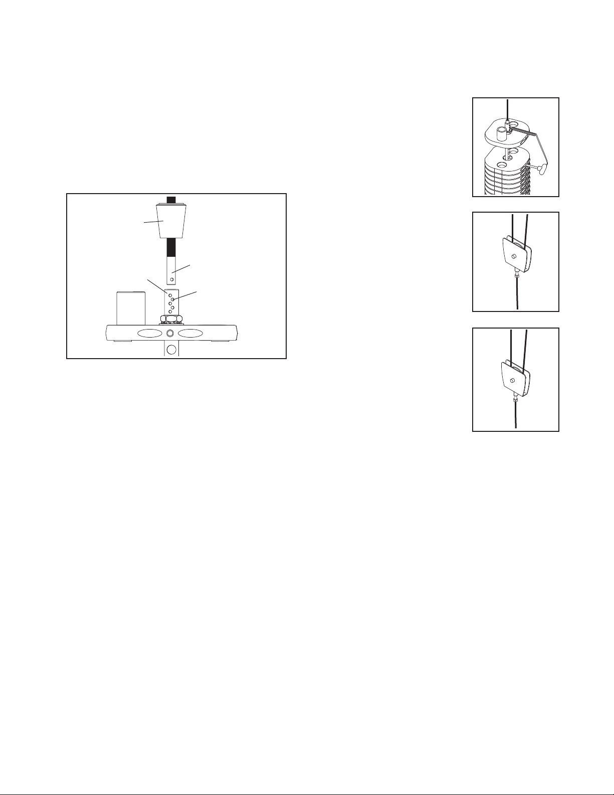
2. Cables:
•Check all cables for proper tension.
•Check the entire length of the cable by pulling
each handle individually to its fully extended
position and inspecting the cable that is
exposed on the exterior of the machine, as well
as the cable inside of the cut stack tower.
•Run your fingers along the cable, paying close
attention at the bends and attachment points.
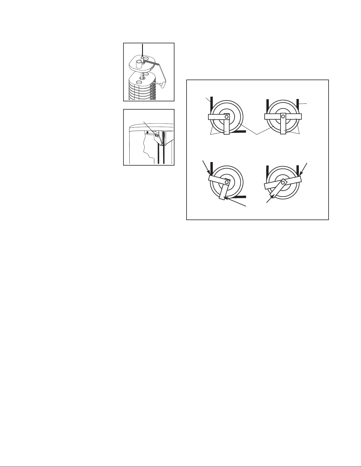
•Watch for the following conditions, which may
indicate a worn cable in need of replacement:
A. torn or split cable sheath that exposes the
cable
B. kinked or severely bent cable
C.curled or twisted sheath
D.stretched cable sheath, showing a thinning
cross-section
A
B
D
C