Ergotron Anthro-DNA Steve's Station Essential User manual

1
ASSEMBLY INSTRUCTIONS
Steve's Station Essential
NOTE: The Monitor Extensions, CPU Holders, displays, and hardware are not included.
Product Part#
Steve's Station Essential, 60w RAD260GV-xx
Steve's Station Essential, 72w RAD272GV-xx
300-5610-00 rev. D
• 09/18
Built with Anthro-DNA™

2
WELCOME!
Thank you for purchasing Steve's Station Essential from Anthro!
PARTS LIST
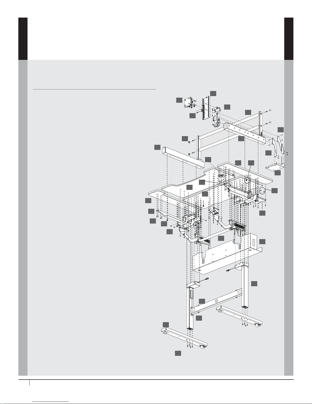
Before beginning assembly of your Steve's Station Essential table, please review the parts list to verify that
your shipment is complete.
2
Product Quantity Part Number
01 Keyboard Surface 1 101-1147-03-00
02 Monitor Surface 1 101-1148-03-00
03 Side Surface X 1
60w table 101-1149-03-00
72w table 101-1159-03-00
04 Side Surface Y 1
60w table 101-1150-03-00
72w table 101-1160-03-00
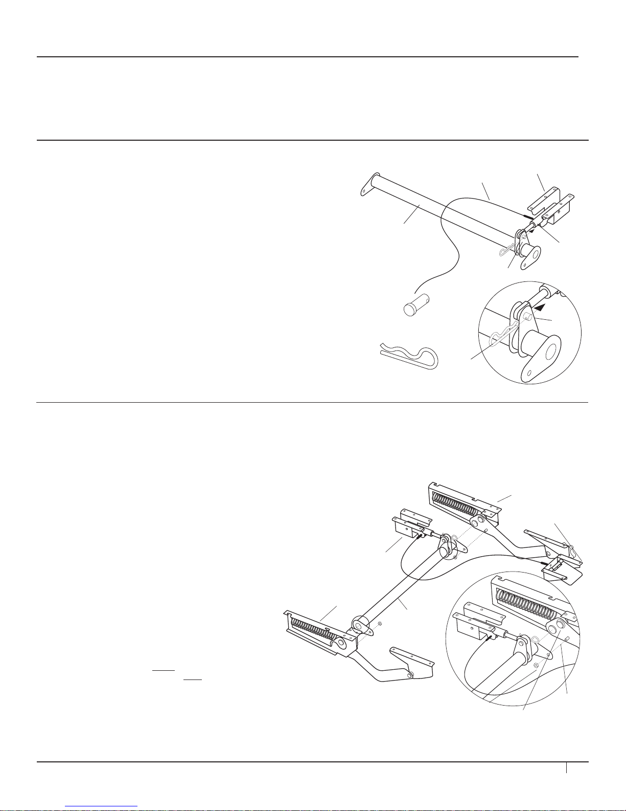
05 Monitor Boom Tube 2 125-5404-03
06 Side Shelf Support X 1 500-1100-56
07 Side Shelf Support Y 1 500-1101-56
08 Cross Tube 1 500-1102-61
09 Cable Trough 1 500-1103-56
10 Adjusta Mechanism 36" 1 225-5546-00
11 Control Box (not shown) 1 400-0953-00
12 Power Cord (not shown) 1 400-5181-00
13 Leg Control Cables (not shown) 2 400-5182-00
14 Keypad 1 400-5357-00
15 Leg 2 575-5087-00
16 Monitor Easy Track Mast Y 1 835-5635-00
17 Monitor Easy Track Mast X 1 835-5636-00
18 Foot 2 835-5637-00
19 Wire Management Clip 5 175-5188-00
20 5/16-18x x 1 Socket Cap Screw 4 325-5136-00
21 M6x20mm Socket Hd Cap Screw 8 325-5272-00
22 #8 x 3/4" Phillips Flat Hd Screw 4 325-5370-00
23 M6x14 Flat Head Cap Screw 4 325-5435-00
24 M6x10mm Button Hd Cap Screw 8 325-5503-00
25 #10-9x3/4" Button Head PB Screw 90 325-5575-00
26 M8-1.25x10 Socket Hd Cap Screw 4 325-5542-00
27 1/4-20x5/8" Button Hd Cap Screw 6 325-5019-00
28 Keypad Slider (not shown) 1 400-5358-00
29 Brake Release Assembly 1 835-5638-03
30 Mount Release Arm X 1 225-4808-00
31 Mount Release Arm Y 1 225-4809-03
32 #8-32 UNF x 3/8 Hex Button Hd
Cap Screw w/Nylon Patch 8 325-5423-00
33 Monitor Bracket Assembly 1 RADKN-01
34 Monitor Track, 12" 1 225-4442-00
35 Block 1 225-4443-00
36 Knuckle Assembly, Standard 1 RADKNA-02
01
02
03
04
05
06 07
08
09
10
14
15
16
17
18
19
20
21
22
23
24
25
26
27
29
30
31
33
34
35
36
300-5610-00 rev. D
• 09/18

3
STEP 1A
ASSEMBLE THE ADJUSTA MECHANISM
Your Adjusta mechanism comes unassembled and
is boxed separately inside the package. Locate the
small bag of hardware included with the Adjusta
Mechanism. It includes (1) Post, (1) Cotter Pin, (2)
Hex Nuts, (2) Wood Screws, and (2) Cable Mounts.
Begin to assemble the mechanism by rst locating
the Crossbar and Brake/Paddle assembly and
position them as shown at right. Depress the
Paddle once to free the Brake Shaft.
Place the Brake Shaft between the two center
Crossbar anges. Insert the Post through both
center Crossbar anges and the Brake Shaft.
Install the Cotter Pin through the single opening of
the post to secure it in place.
STEP 1B
ASSEMBLE ADJUSTA ARMS
Unpack the remaining Adjusta mechanism
components and arrange them as shown at right.
Place one Crossbar End onto the lower Crossbar
Button and Threaded Bolt located on each Arm
Mechanism. Secure the Crossbar to the Arm
Mechanism using one 5/16" Hex Nut onto the
Threaded Bolt.
Repeat for remaining Crossbar End and Arm
Mechanism.
Cotter Pin
(included with 225-5548-00)
Cotter Pin
Post
Center Crossbar
Flanges
Brake
Shaft
Crossbar
Post
(included with
225-5548-00)
Brake/Paddle Assembly
Brake Cable
Arm Mechanism
Threaded
Bolts
5/16" Hex
Nut
Paddle
Brake/Paddle
Assembly
Arm Mechanism
Crossbar
Lower Crossbar
‘Button’
NOTE: it is very important that you attach the
Crossbar ONLY to the Lower Crossbar Button.
TOOLS
The following tools are provided for this assembly. If you choose to use a power drill, set the torque setting to mid-
range.
5/32" hex Anthro driver 3/16" hex looped T-handle 5mm hex key 6mm hex key
1/4" hex key 3/32" hex key 5/32" hex driver bit
300-5610-00 rev. D
• 09/18

4
STEP 3
ATTACH ADJUSTA MECHANISM TO KEYBOARD SURFACE
Slide the Keyboard Surface under the mechanism
arms. Align the three holes on each end of the
Keyboard surface with the three holes on each
mechanism arm. Secure the arms to the Keyboard
Surface with six 3/4" Button-hd PB Screws.
Position the Paddle on the Keyboard Surface so the four holes on the
Paddle align with the four holes on the Keyboard Surface and the brake
cable runs under the Adjusta Bar. Secure the Paddle to the Keyboard
Surface with four 3/4" Button-hd PB Screws.
Install one cable clip into the pre-drilled hole next to the Brake Assembly
and route the brake paddle cord through it.
STEP 2
ATTACH ADJUSTA MECHANISM TO MONITOR SURFACE
Loosely attach each Mechanism Arm to the Monitor
Surface using a total of twelve 3/4" Button-hd PB
Screws (325-5575-00).
Align the Paddle Brake Assembly with the six holes
on the Monitor Surface. It may be necessary to
depress the paddle in order to position the brake.
Secure the brake assembly with six more 3/4" Button-hd PB Screws.
3/4" Button Hd PB Screw
325-5575-00
3/4" Button Hd PB Screw
325-5575-00
Mechanism Arm
Mechanism Arm
Paddle Brake Assembly
300-5610-00 rev. D
• 09/18

5
STEP 4
ATTACH LEGS TO SIDE SHELF SUPPORTS
Align one leg with the Side Shelf Support so the
leg’s motor housing nests inside the cavity in the
Support and the side of the leg rests against the
Support’s inside face. [A]
Loosely attach the leg to the Side Shelf Support
with two M6-10 Button-hd Screw (325-5503-00)
each on the front and back of the leg. [B]
Attach the outside face of the leg to the tall face of
the weldment with two M6x14 Flat Head Screws
(325-5435-00) using the Anthro driver. Tighten
these two fasteners all the way, then tighten the
four button-head screws. [C]
Repeat for the second leg and support.
STEP 5
INSTALL CROSS TUBE ONTO LEG ASSEMBLIES
Place the two side shelves upside down next to the shelf assembly. Place each leg assembly on the shelves so the
holes in each support line up with the holes on the shelves, so the leg cord faces the inside of the table, and the
long arms of the support point to the front of the table. Don’t attach them yet – just set them into place. [A]
Locate the two threaded holes on each leg near the motor housing. Hand tighten one fastener (M8-1.25x10
Socket-hd Cap Screw), 325-5542-00, into each hole closest to the motor housing on each leg. Leave a gap of about
1/4" between the screw head and the motor housing. [B]
Align the Cross Tube with each leg assembly so that the Anthro logo faces the front of the table and the slots at the
end of the Cross Tube line up with the fasteners. Slip the Cross Tube onto the fasteners then loosely attach using
two more fasteners through the holes above the slots. [C]
Tighten all four Cross Tube fasteners.
A
B
C
M6-10 Button-head Screw
325-5503-00
A
B
CD
M6x14 Flat Hd Screw
325-5435-00 Side Shelf Support for 60w table shown.
M8-1.25x10 Sockt-hd Cap Screw
325-5542-00
300-5610-00 rev. D
• 09/18

6
STEP 7
ASSEMBLE AND INSTALL CABLE TROUGH
Secure control box to Cable Trough using the nuts
(325-5186-00) and machine screws (325-5086-00)
provide as shown to the right.
Align the Cable Trough with the Monitor Surface so
the open side of the trough faces the back of the
table and the holes on the top of the trough line up
with six holes on the monitor surface.
Attach the trough to the Monitor Surface with six
3/4" Button-hd PB Screws (325-5575-00) through
the center holes on the trough. Install one more
screw at each end of the cable trough using the
holes you skipped in Step 6.
Attach the Leg Control Cables to each leg and plug them into ports on the Control Box inside the Cable Trough.
Plug the Power Cord into the Control Box. Install one cable clip next to each leg and route a Leg Control Cable
through each. Use the zip ties to anchor each Leg Control Cable to the slots on the trough, clear of the springs in
the mechanism.
3/4" Button Hd PB Screw
325-5575-00
STEP 6
INSTALL LEG ASSEMBLY ONTO MONITOR SHELF
Attach the Leg Assembly to the Monitor Shelf using
eleven 3/4”PB Screws (325-5575-00). You’ll want to
use twelve, but don’t do it. Skip the indicated holes;
you’ll ll them when you attach the Cable Trough
later.
3/4" Button Hd PB Screw
325-5575-00
Skip these holes...for now!
Cable Snap-in Clip
175-51188-00
300-5610-00 rev. D
• 09/18

7
STEP 9
INSTALL BOOM MASTS
Locate the two Boom Mast Assemblies. One has a
cable coming o of it (that’s Boom Mast Y) and the
other doesn’t (that’s Boom Mast X).
Align Boom Mast X (no cable) with the left side
of the table so the bottom of the mast slides into
the Side Shelf Bracket at the edge of the table.
Very loosely (just one turn) attach the mast to the
bracket with three 5/8" screws (325-5019-00)
Repeat to very loosely install Boom Mast Y onto the
right-hand side of the table.
STEP 8
INSTALL THE FEET
Align one Foot with a leg so the wheel and threaded glide face up and the
wheel is over the back of the table.
Install the Foot to the Leg with four M6-20 Cap Screws (325-5272-00).
Repeat for the second Foot.
With the help of at least one other person, rotate the table onto its feet.
M6-20 Cap Screw
325-5272-00
1/4-20 x 5/8" BH Cap Screw
325-5019-00
300-5610-00 rev. D
• 09/18

8
STEP 10
INSTALL BOOM CROSS TUBES
Loosely install the two Boom Cross Tubes between
the masts with two 5/16”-18x1” (325-5136-00)
Socket-head screws each using the 1/4”driver. [A]
Locate the Monitor Bracket. Remove the knob
and open the bottom clamp. Hook the top of the
Monitor Bracket over the top cross tube then close
the bracket's bottom clamp over the bottom tube.
Re-install the knob loosely. [B]
Slide the Bracket all the way to the left side of the table and tighten the Cross Tube Fasteners on the adjacent Boom
Mast. Next, slide the Bracket all the way to the right side of the table and tighten the Cross Tube Fasteners there.
Slide the Knuckle to the center of the Cross Tube.
Align the Monitor Track with the front of the Monitor Bracket so that the top holes on the bracket line up with the
pair of holes 8 down from the top of the track. Attach with two 325-5423-00 fasteners. Count up seven holes from
the bottom and attach with two more 325-5423-00 fasteners. [C]
Remove and set aside the safety fastener at the top of the Monitor Track [D].
Slide the Monitor Block into the track with the hooks facing down. Hook it into the slots on the Monitor Track at
the desired height [E].
Locate the four End Caps in your kit. Pop the End Caps to cover the ends of the cross tubes.
AB
1” Socket-head Cap Scre
w
325-5136-00
CDE
#8-32 UNFx3/8 Hex BHCS
325-5423-00
300-5610-00 rev. D
• 09/18

9
STEP 11
INSTALL BRAKE ASSEMBLY
Locate the Monitor Boom Brake Mechanism. Using the 3/32” Hex Key, remove the four fasteners that attach the
mechanism’s bottom plate. Set aside the fasteners and plate. [A]
Locate the cable on Boom Mast Y. Slip the end of the cable into the slot at the end of the Brake Assembly so that
the gap at the bottom of the cable tting ts into the top inner plate in the brake assembly. Use the side of a large
hex key or the Anthro driver to press the housing into place until it clicks. Pull the bead at the end of the cable so it
is below the middle inner plate as shown. If needed, use pliers to pull the bead of the cable out of the tting so it's
long enough to reach. [B]
Reattach the bottom plate. Locate the Brake Arms. Attach the arms to the mechanism as shown with two
#8-32 Button-hd Cap Screws (325-5423-00) each using the 3/32” Hex Key. [C]
Align the Brake Assembly with the Knuckle so the holes on the arms line up with the holes on each side of the
bracket.
Attach the Brake Assembly to the bracket with four more #8-32 Button-hd Cap Screws. [D]
Slide the Boom Assembly all the way back and tighten the Boom Mast Fasteners at the back of the table. Slide the
Boom Assembly all the way forward and tighten the Boom Mast Fasteners at the front of the table.
A
C
D
#8-32 UNFx3/8 Hex BHCS
325-5423-00
B
Gap
Bead
Top Inner Plate
Middle Inner Plate
300-5610-00 rev. D
• 09/18

10
STEP 13
INSTALL KEYPAD AND CONNECT CORDS
Align the keypad with its housing so the keypad rests inside the housing
and the buttons face up. Align the assembly with the right-hand side shelf
so the holes on the assembly line up with the holes on the shelf.
Attach the keypad assembly to the shelf with four 3/4” Phillips Flat-head
Screws using your Phillips screwdriver.
Route the keypad cord through the clips, through the openings on the side
shelf support, and plug the cord into the Control Box.
Plug leg cords into the Control Box.
Plug the power cord into the Control Box and into the wall. Home the
legs by pressing the DOWN button until the table is at its lowest position.
Release the button, then press DOWN again until the table settles into
position. This keeps the legs in sync.
3/4” Phillips Screw
325-5370-00
STEP 12
INSTALL SIDE SHELVES
Locate the two Side Shelves. Align one Side Shelf
with the table so the holes on the bottom of the
shelf line up with the holes on the Side Weldment.
Attach the shelf to the weldment with sixteen 3/4”
MDF Screws using the Anthro driver.
Repeat for the second Side Shelf.
3/4" Button Hd PB Screw
325-5575-00
300-5610-00 rev. D
• 09/18

11
STEP 14
INSTALL YOUR MONITOR
To install a monitor onto your table, attach the knuckle to your monitor.
Place your monitor face down on a non-marring surface with the top of the
monitor away from you.
Align the knuckle with the monitor so the holes on the knuckle line up with
the holes on the back of the display and the tilt release lever is on the right.
Attach the knuckle to the monitor with four M4x8mm Phillips screws
(325-A129-18-01-00). If the knuckle won't t into the attachment area on
the back of your display, use the spacers (325-5640-00) and the longer
M4x18mm (325-A300-05-01-00) screws.
Slide the Monitor and Knuckle Assembly into the track until it rests on the block. Check the height. If needed, slide
the assembly out, reposition the Monitor Block, and reinstall the Monitor and Knuckle assembly.
Once all knuckles are installed, ne-tune their height and “yaw” (side-to-side tilt). Two height adjustment screws are
located on the back of the knuckle just above the block, one on the left side and one on the right. Insert the long
3/16” hex key into the opening and turn clockwise to move that side up, counter-clockwise to move it down.
Yaw Adjustment Screws
AB
STEP 15
INSTALL COMPUTERS, POWER, AND OTHER EQUIPMENT
Install Power Bar, if purchased. Slide it into the cable trough and plug in your equipment. You can even plug your
table into the Power Bar and send a single power cord to the wall!
Install CPU SideRacks, if purchased, using their enclosed instructions.
300-5610-00 rev. D
• 09/18
© 2018 Ergotron, Inc. All rights reserved.
All trademarks are the property of their respective companies.
Anthro is a registered trademark and brand of Ergotron Inc.
Anthro-DNA is a trademark of Ergotron Inc.
For local customer care phone numbers visit: http://contact.ergotron.com
For Service visit: www.ergotron.com
For Warranty visit: www.ergotron.com/warranty
Table of contents
Other Ergotron Office Equipment manuals
Popular Office Equipment manuals by other brands

Narbutas
Narbutas Silent Room M Operation manual

Koplus
Koplus KOLO DUO Assembly instructions

3-form
3-form SimpleSpec 200.91-Divide installation manual

Herman Miller
Herman Miller Canvas Office Landscape Support Panel Installation and Disassembly for Recycling Instructions

Panasonic
Panasonic Jetwriter KX-CLPF1 Service manual

PG BISON
PG BISON OFFICE FURNITURE BLUM FLATPAX Assembly guide