ERHARD ERU K1 User manual

BA46E042
Jul 2009
Rev. 11
ERHARD-Armaturen D-89502 Heidenheim PO box 1280
(+49-7321) 320-0 (+49-7321) 320 491 e-mail: info@erhard.de
Internet: http://www.erhard.de
Page 1 of 12
BA46E042
Operating instructions
ERHARD-ERU Knife Gate Valve
K1
DN 350 - 600
electric actuator
1 Product description and range of application
2 Design features - technical data
3 Function and mode of operation
4 Storage
5 Installation into the pipeline –mounting
6 First time operation
7 Operation and use
These operating instructions must always be used in connection with BA01E001!
1 Product and function description
ERU Knife Gate Valve K1
with rising stem
Design for automatic operation with electro actuator
Make no.: 4607 .... PN 4
4617 ... PN 6
4657 .... PN 10

Operating instruction ERU Knife Gate Valve K1 electric actuator
BA46E042
Jul 2009
Rev. 11
ERHARD-Armaturen D-89502 Heidenheim Postfach 1280
(07321) 320-0 (07321) 320 491 e-mail:info@erhard.de
Internet: http://www.erhard.de
Page 2 of 12
Size
Nominated pressure
Hydr. Test pressure in bars Max. admissible
DN PN
for
working pressure in bars at
body end seal working temperature < 60°C
Erz.-Nummer
350 10 17 11 10 4655....; 4657....
400-600 4 8 4,4 4 4605....; 4607....
400 - 600 6 12 6,6 6 4615....; 4617....
400 - 600 10 15 11 10 4655....; 4657....

Operating instruction ERU Knife Gate Valve K1 electric actuator
BA46E042
Jul 2009
Rev. 11
ERHARD-Armaturen D-89502 Heidenheim Postfach 1280
(07321) 320-0 (07321) 320 491 e-mail:info@erhard.de
Internet: http://www.erhard.de
Page 3 of 12
2 Design features –technical data
Drawing 3. 60796
ERU Knife Gate Valve K1 with electro actuator
- Flange connection dimensions according to DIN EN1092, PN10, previously DIN 2532 PN10
- Connection elements for flange connection according to drawing 4.131899
- Overall length EN558-1, Basis series I HE 20, previously DIN3202, part 3, series K1
Operating instruction ERU Knife Gate Valve K1 electric actuator
BA46E042
Jul 2009
Rev. 11
ERHARD-Armaturen D-89502 Heidenheim Postfach 1280
(07321) 320-0 (07321) 320 491 e-mail:info@erhard.de
Internet: http://www.erhard.de
Page 4 of 12
Parts list to drawing: 3. 60796
ERU Knife Gate Valve K1 with electro actuator
In the column "E/V" are marked
spare parts or sets, respectively, e.g. E1 = spare parts set No. 1
or
wearing parts, spare parts or sets, respectively, e.g. V1 = wearing parts
set No. 1
and in column 2j (for 2 years of operation or as needed, respectively)
Part
Name
eac
h
2
j
E / V
Part
Name
each
2
j
E / V
1
Body part
2
13
Washer
*)
2
Bow cpl.
1
x
V1
14
Bow attachment
1
3
Round key
*)
15
Bushing
1
x
E2
4
Pressure piece
2
16
Stem
1
x
E1
5
Gaskets 4kt
4
x
V1
17
Bolt
*)
x
E2
6
Profile rubber
2
x
V1
18
Retaining washer
*)
x
E2
7
Sliding plate
1
19
Washer
4
8
Washer
*)
20
Cheese head
screw
4
9
Hexagon bolt
*)
21
Electro actuator
1
10
Hexagon nut
*)
22
Washer
4
11
hexagon bolt
*)
23
Cheese head
screw
4
12
Hexagon nut
*)
*) according to DN varying quantities
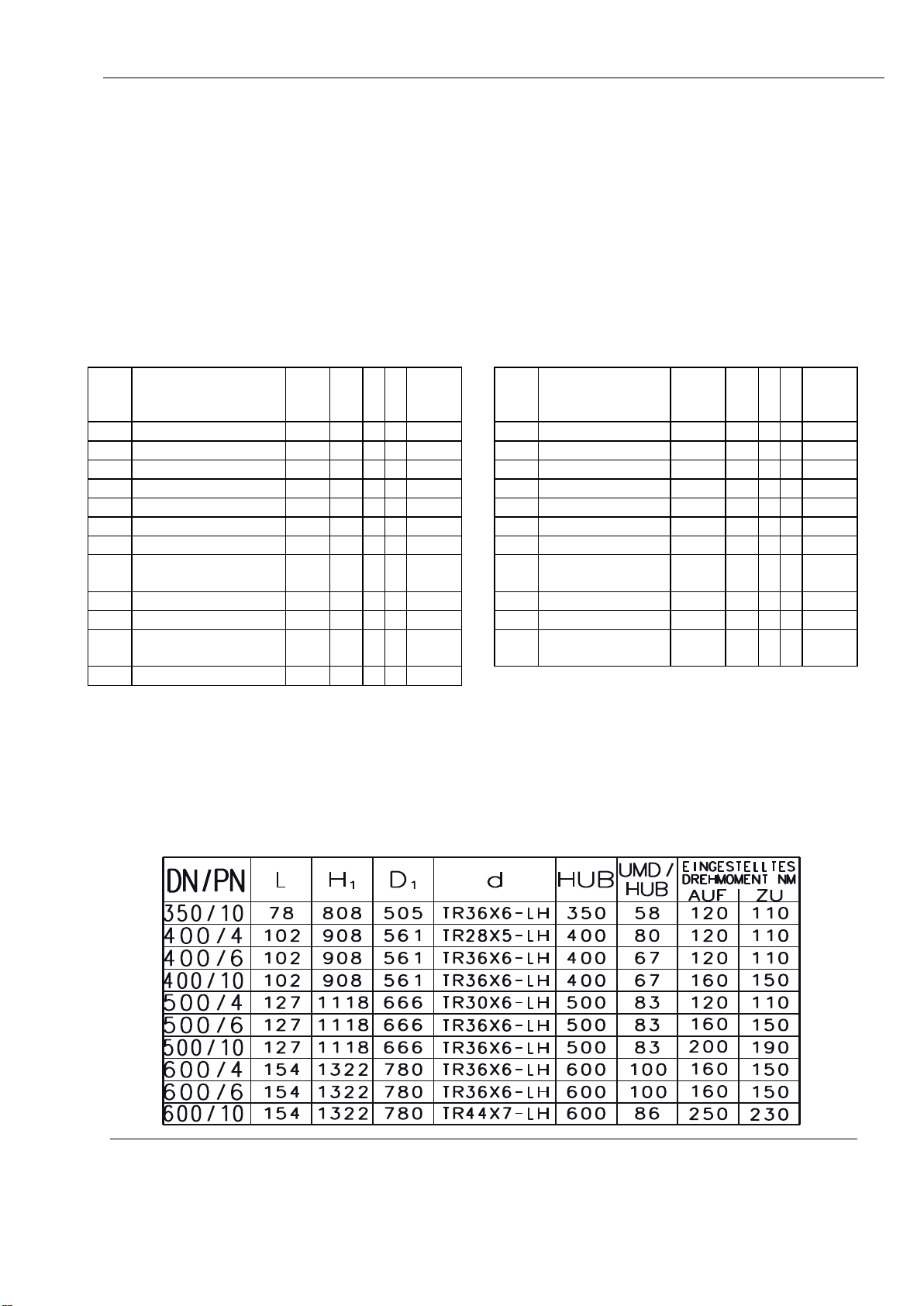
Table of dimensions to drawing: 3. 60796
Stroke UMD / Set
stroke torque Nm
Operating instruction ERU Knife Gate Valve K1 electric actuator
BA46E042
Jul 2009
Rev. 11
ERHARD-Armaturen D-89502 Heidenheim Postfach 1280
(07321) 320-0 (07321) 320 491 e-mail:info@erhard.de
Internet: http://www.erhard.de
Page 5 of 12
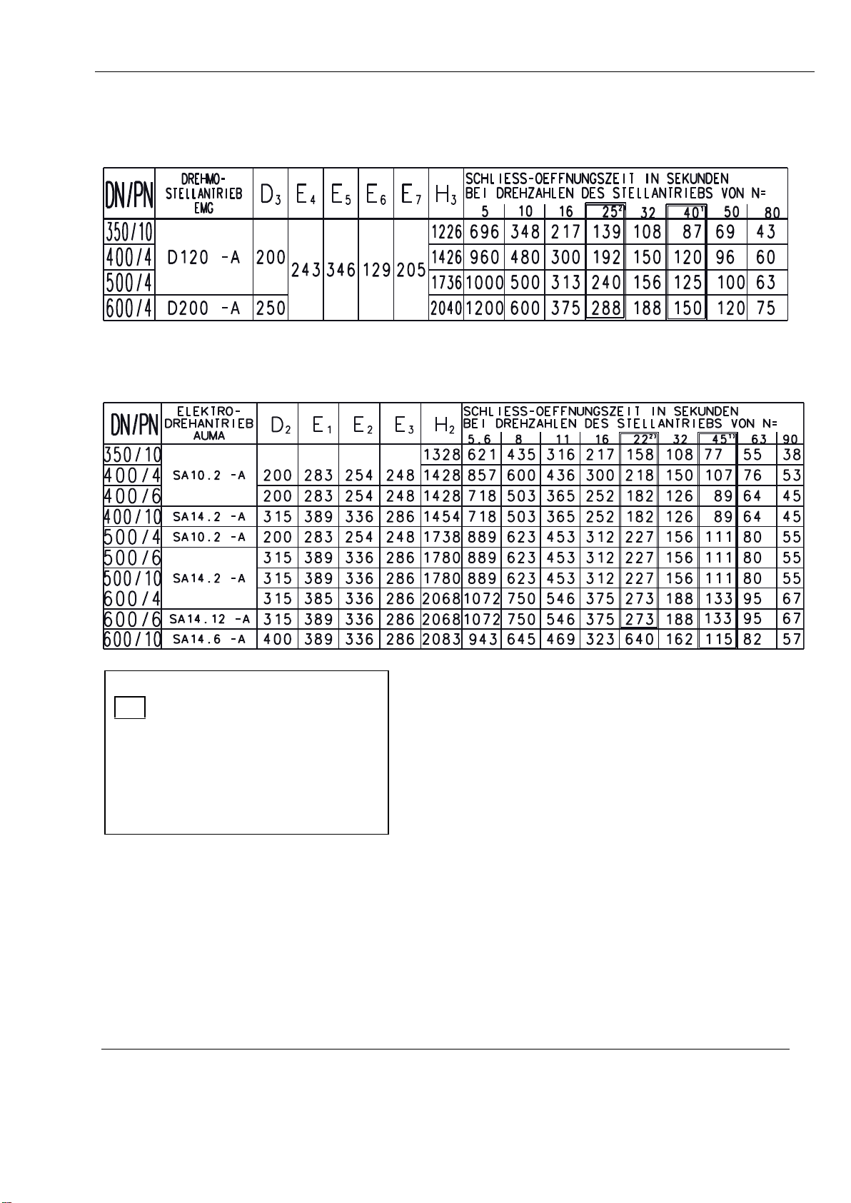
Table of dimensions to drawing:3. 60796
Torque actuator Closing-opening times in sec.
EMG at rotational speed of the actuator of N=
Electro Closing-opening times in sec.
rotational actuator at rotational speed of the actuator of N=
AUMA
Preferred series
1)
at standard actuator
2)
at control actuator

Operating instruction ERU Knife Gate Valve K1 electric actuator
BA46E042
Jul 2009
Rev. 11
ERHARD-Armaturen D-89502 Heidenheim Postfach 1280
(07321) 320-0 (07321) 320 491 e-mail:info@erhard.de
Internet: http://www.erhard.de
Page 6 of 12
3 Function and mode of operation
ERU Knife Gate Valves K1 are single plate knife gate valves with clamping installation
design featuring short overall lengths, suitable also for control purposes due to special
design e.g. with regulating piece. Between two body sections the solid sliding plate is
moving in a long plate guide. Its perimeter seals against a rubber elastic steel
reinforced chambered U-bow. At the exit of the sliding plate from the body the sliding
plate seals by an elastically biased profile gasket to the outside. This profile gasket is
adjustable. For reducing wear of the profile gasket and the actuator elements the bias
can be reduced to the value needed for actual operation.
The slides have been tested at the manufacturers for strength and tightness according
to DIN EN 12266 and DIN EN 1074. They allow operation in both flow directions.
4 Storage
ERU Knife Gate Valves K1 must be stored in closed condition. Rubber lined parts,
such as bows between body sections must be protected against direct sun radiation.
Influence of radiant heat e.g. from radiators should be avoided.
5 Installation into the pipeline - mounting
All packaging material must be removed from the valve. Prior to installation, the
pipeline must be inspected for pollutions and foreign parts and be cleaned if
necessary.
Care should be taken that the valve is accessible from all sides for
operation and maintenance.
At operating media with solids, such as sand etc. and installations in horizontal lines
the stem or piston rod, respectively, should not be installed inclined more than 30º
to the horizontal position. Thus rinsing free of the stroke area of the sliding plate
becomes possible.
At different installation positions, especially at hanging stem or piston rod,
respectively, deposits may be built-up around the sliding plate. That could cause
functional failures and maintenance could become more extensive.
During the mounting process the valve should have a distance between the pipeline
flanges which is at least 20 mm larger than the overall length of the valve, in order
not to damage the work strips and allow gaskets to be put in. As flange gaskets
steel reinforced flat gaskets are recommended (rubber gaskets) according to DIN
EN 1514-1. At lap-joint flanges mandatory required. Media and temperature
compatibility of the gaskets must be observed and to be checked.
The pipeline counter flanges must be plane parallel and concentric.

Operating instruction ERU Knife Gate Valve K1 electric actuator
BA46E042
Jul 2009
Rev. 11
ERHARD-Armaturen D-89502 Heidenheim Postfach 1280
(07321) 320-0 (07321) 320 491 e-mail:info@erhard.de
Internet: http://www.erhard.de
Page 7 of 12
Connection screws must be tightened equally (tension free) and crosswise. In no
case the pipeline may be pulled to the valve.
Should the distance between the flanges be too large for the valve the difference
must be compensated by thicker flat gaskets.
ERU Knife Gate Valves K1 are either
- clamped between two flanges of the pipeline, or
- screwed as end-of-line valve on the end flange.
When installing into the pipeline, the special flange bore pattern must be observed
at this type of valve. One part of the screws connects the pipeline flange with the
body. The other part is located alongside the body from pipeline flange to pipeline
flange.
6 First time operation
Attention: prior to first time operation stem and stem nut must be greased (for
recommended grease see section „Operation and use“).
The electro actuator is mounted concentrically on the bock attachment of the ERU
Knife Gate Valve K1. The stem of the valve is moved by the threaded bushing of the
electro actuator in vertical direction (ON - OFF). The actuators are equipped in the
standard version with:
Torque and travel switch with 1 open + 1 close contact each per rotational direction,
flasher unit for indicating the run,
heater in the switching room,
thermal switch in the motor winding.
ERU Knife Gate Valves K1 are switched off in both end positions depending on
travel.
The switching points of the end position switches are set in the factory during leakage
tests at nominal pressure. It will be considered that blocking of the sliding plate against
the upper mechanical end caused by motor run-on will be avoided and starting from
there will be no problem. The torque switches serve as safety switches, e.g. at
intermediate positions.
If the valve is supplied without attached electro actuator the travel switches should be
set after mounting the electro actuators.
See also section 6.2 "First time operation of the electro actuator", paragraph
"Resetting of travel switch".
The relevant safety regulations (VDE/TAB etc.) and instructions of the electro actuator
manufacturer for transport, storage and first time operation must be observed.

Operating instruction ERU Knife Gate Valve K1 electric actuator
BA46E042
Jul 2009
Rev. 11
ERHARD-Armaturen D-89502 Heidenheim Postfach 1280
(07321) 320-0 (07321) 320 491 e-mail:info@erhard.de
Internet: http://www.erhard.de
Page 8 of 12
Electrical connections must be made according to operating instructions as well as
switching and connection plan of the electro actuator manufacturer (travel distance,
torque and thermal switches, heater motor). Prior to installation the isolation resistance
of the motor must be measured. In case it is below 500 kΩit means there is humidity
in the winding. The motor must be removed for drying and be warmed up by means of
a hot-air blower or in a heated chamber: maximum admissible temperature = 100°C.
Inching and emergency manual operation
Attention:
If a foreign part will be trapped during operation of the valve the torque switch for the
corresponding direction will trip and switch off the motor.
The time between tripping of the torque switch and separation of the motor from mains
depends on signal travelling time. If now a new command will be given for the previous
direction without having rotated the valve sufficiently far enough into the opposite
direction, the torque will rise. If this procedure will be repeated several times the
momentum will be cumulated. The valve and its actuator parts are not designed for
such a case of failure and may be damaged.
We point express to the fact that such an "Inching" is not admissible.
Inching is admissible as follows:
If the torque switch trips at an intermediate position, first, it must be travelled far
enough into the counter direction until the torque switch reaches completely its home
position. Only then, restart into that direction in which the failure has occurred is
admissible. At this procedure torques will be reached which correspond with the set
momentum on the torque switch. Moreover, the foreign part can loosen and be flooded
out from the seat area.
Operating by emergency manual operation (hand wheel):
If the valve will be operated by hand wheel of the electric actuator the torque switches
have no securing effect.
If a foreign part is trapped at an intermediate position, excessive force may lead to
damages on the actuator parts - especially at heavy geared down equipment.
Therefore it must be observed:
If during emergency manual operation a resistance will be noticed, one turn into the
counter direction must be performed prior to rotating into that direction in which the
failure has been detected (rinsing out the foreign part). Operation should be performed
at utmost care, in no case use excessive force, if required rinsing should be repeated.
The profile gasket has been set to nominal pressure in the factory (biased). At low
operating pressures the profile gasket can be released after the pressure test of the
pipeline according to actual operating pressure. For doing this, the screws on the

Operating instruction ERU Knife Gate Valve K1 electric actuator
BA46E042
Jul 2009
Rev. 11
ERHARD-Armaturen D-89502 Heidenheim Postfach 1280
(07321) 320-0 (07321) 320 491 e-mail:info@erhard.de
Internet: http://www.erhard.de
Page 9 of 12
cover plate shall be loosened accordingly. By this measure wear of components
involved in movements can be reduced.
ATTENTION ! Operating media may escape. In case of poisonous or corroding media
wear protective clothing (goggles).
First time operation of the electro actuators
For first time operation of the valve the operating instructions of the electro actuator
manufacturer must be referenced to.
6.1.1 Rotate ERU Knife Gate Valve K1 manually into intermediate position.
6.1.2 By short time electrically starting the plate movement and thus direction of
rotation of the actuator has to be checked.
valve closes = actuator direction RIGHT (clockwise)
valve opens = actuator direction LEFT
6.1.3 At wrong direction of rotation change poles on the motor connection
6.1.4 Check direction of rotation by short time electrically starting
6.1.5 Check correct switching sequence of the torque switches in "OPEN-CLOSED"
direction by manual operation
6.1.6 Change poles if required
6.1.7 Only after the direction of rotation "RIGHT for valve closes" is met you may
travel over the complete stroke.
At wrong direction of rotation travel and torque switches do not have any
effect !
6.2 Resetting of the travel switches:
6.2.1 Rotate valve manually to end position "OPEN"
6.2.2 Reverse by approx. 5mm stroke
6.2.3 Adjust travel switch "OPEN" according to operating instructions of the electro
actuator manufacturer
6.2.4 Rotate valve manually into closed end position "CLOSED"
6.2.5 Adjust travel switch "CLOSED" according to operating instructions of the
electro actuator manufacturer
If these suggested measures will not be adhered to we will not accept any
liability for possibly occurring damages.

Operating instruction ERU Knife Gate Valve K1 electric actuator
BA46E042
Jul 2009
Rev. 11
ERHARD-Armaturen D-89502 Heidenheim Postfach 1280
(07321) 320-0 (07321) 320 491 e-mail:info@erhard.de
Internet: http://www.erhard.de
Page 10 of 12
7 Operation and use
Prior to first time operation stem and stem nut must be greased.
At operating media water the recommended lubricant is Klüber Unisilikon L641.
At operating media water silicon free types the recommended lubricant is Klüber Synth
VR 69-252.
At the electro actuator a gap between sliding plate and bearing plate remains visible
(run-on).
The cross gaskets are set to nominal pressure in the factory (biased). They can be
adapted to the actual operating over pressure: by loosening the counter nut and
screws the bias of the gasket will be reduced.
ATTENTION ! Operating media may escape. In case of poisonous or corroding
media wear protective clothing (goggles).
The valve plate (gate) should be always cleaned and lubricated depending on the
operating and environmental conditions.
ERU Knife Gate Valves K1 should be operated in regular short intervals (every six
months) over the complete stroke (OPEN-CLOSED). Depending on operating media
and the conditions at place of use the maintenance intervals could be shorter or
longer.
As soon as a minor leakage will be detected the cross gaskets must be brought into
tight condition by equally tightening the screws.
Tighten counter nuts. By this adaptation to the actual operating conditions the
operating force will be reduced and service life of the cross gaskets will be increased.
If re-tightening of the cross gasket should be no more possible they must be
replaced.
Sliding plate and stem must be inspected for pollution in regular intervals and be
cleaned if required and be treated with lubricants (thin application).
ERU Knife Gate Valves K1 which are equipped with grease nipple in the area of the
stem bearing must be re-greased with regards to usage conditions in regular
intervals.
If sluggishness will continue it should be checked if the valve has possibly been
pressed too hard between the flanges of the pipeline. The through flange screws
must be loosened equally and ease of movement should be re-checked.
Please see also section "Operating failures which can be solved by yourself "

Operating instruction ERU Knife Gate Valve K1 electric actuator
BA46E042
Jul 2009
Rev. 11
ERHARD-Armaturen D-89502 Heidenheim Postfach 1280
(07321) 320-0 (07321) 320 491 e-mail:info@erhard.de
Internet: http://www.erhard.de
Page 11 of 12
7.1 Not admissible modes of operation
For inspections or maintenance works the valve - or parts of the valve - may only be
dismantled after the line section in which they are installed is blocked and be made
pressure less. If works are performed in the vicinity of the valves which may lead to
pollutions (concrete, brick laying, painting works, sand blasting and the like) valves
must be covered appropriately.
At equipping the ERU Knife Gate Valves K1 with EPDM profile gaskets the EPDM
parts may not be greased with oil or come into contact with grease, since EPDM
swells. For the recommended grease see section 7.
The ERU Knife Gate Valves K1 of this type are not suitable for control purposes. For
extensive control operation special types, e.g. with regulating piece should be used.
Elongation of operating elements by levers or the like is not admissible, Risk of
damages !

Operating instruction ERU Knife Gate Valve K1 electric actuator
BA46E042
Jul 2009
Rev. 11
ERHARD-Armaturen D-89502 Heidenheim Postfach 1280
(07321) 320-0 (07321) 320 491 e-mail:info@erhard.de
Internet: http://www.erhard.de
Page 12 of 12
7.2 Operating failures which can be solved by yourself:
Failure
Possible cause
Remedy
Leakage at the
cross gasket
Not enough bias,
possibly higher
operating pressure than
set
Re-adjustment of the cross gasket: see
"6. First time operation".
Wear of the PTFE
gaskets
Replace gaskets
Pollution (residues) on
the sliding plate
At valve open position: clean plate on both
sides and grease
Leakage at the
plate face
Bias of the upper body
screws
Tighten body screws at installed valve
Leakage at
body girth
Bias of the
body screws
First tighten through screws from flange to
flange and as far as can be reached body
screws. If no success: replace bow
Leakage at end
seal
Pollution of the plate,
defective bow
Clean plate and grease,
replace bow
Sliding plate runs on
one side onto the body
Loosen bias of the cross gasket on both
sides. Renew bias setting on both sides
equally, in order to let the sliding plate run
centrically.
Operating force
too high
Bias of the cross gasket
too high
Loosen cross gasket
see "First time operation".
Pollution (residues) on
the sliding plate
At valve open position: clean plate on both
sides and grease
Spindle
runs dry
Re-grease thread
Actuation
blocks
Operating media
residues became
hardened
Line section pressure less. Clean all
accessible surfaces of plate and stem and
grease. Loosen cross gasket on both sides.
Loosen upper body screws slightly. Beat
with rubber hammer on the valve and try to
operate the valve at the same time. In case
of no success, remove, dismantle, clean,
replace damaged parts.
Other manuals for ERU K1
1
Table of contents
Other ERHARD Control Unit manuals


Popular Control Unit manuals by other brands


Speakman
Speakman CPV-P-IS Installation, operation & maintenance instructions

Vertiv
Vertiv Geist Replacement guide

Pentair
Pentair HI FLOW SIX-WAY 1-1/2 INCH TOP MOUNT VALVE Installation and user guide

Satel
Satel ETHM-1 manual

Atmel
Atmel ATBTLC1000 BluSDK user guide

iSmartHome
iSmartHome id Smart Box Operation manual


