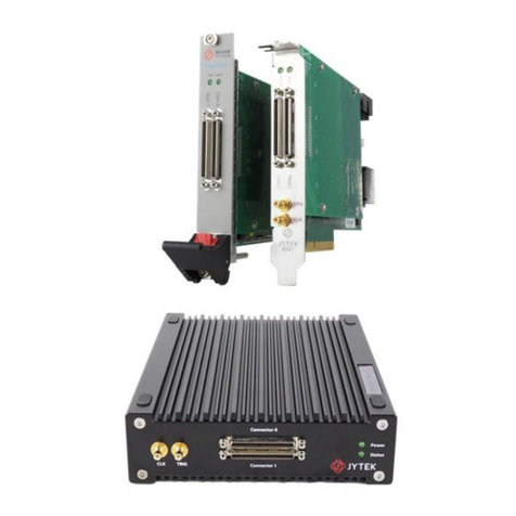
JYTEK PCIe-5211 User manual

User Manual Version:
Revision Date:
V1.6.2
Oct . 09, 2021
PCIe/PXIe-5211
Counter/Timer Module
User Manual

Table of Contents
1.Overview................................................................................................................ 1
1.1 Introduction......................................................................................................1
1.2 Main Features.................................................................................................. 1
1.3 Abbreviations................................................................................................... 1
1.4 Learn by Example............................................................................................. 2
2.Hardware Specifications............................................................................................ 4
2.1 System Diagram................................................................................................4
2.2 Digital IO Specifications....................................................................................5
2.3 Counter/Timer Specifications...........................................................................6
2.4 Other Specifications......................................................................................... 7
2.5 Front Panel and Pin Definition......................................................................... 8
2.6 Default Routing for Counter Input/Output Signals........................................10
3.Software....................................................................................................................11
3.1 System Requirements.................................................................................... 11
3.2 System Software.............................................................................................11
3.3 C# Programming Language............................................................................ 11
3.4 PCIe/PXIe-5211 Series Hardware Driver........................................................ 12
3.5 Install the SeeSharpTools from JYTEK............................................................ 12
3.6 Running C# Programs in Linux........................................................................12
4.Operating PCIe/PXIe-5211....................................................................................... 14
4.1 Quick Start......................................................................................................14
4.2 Digital I/O Operations.................................................................................... 14
4.3 Counter Measurement Operations................................................................15
4.3.1 Edge Counting..................................................................................... 15
4.3.2 Pulse Measurement............................................................................ 22
4.3.3 Frequency Measurement....................................................................28
4.3.4 Period Measurement.......................................................................... 33
4.3.5 Two-Edge Separation.......................................................................... 35
4.3.6 Quadrature Encoder............................................................................40
4.3.7 Two-Pulse Encoder..............................................................................46
4.4 Counter Generation Operations.................................................................... 50
Learn by Examples........................................................................................52
4.5 Clocks..............................................................................................................54
4.5.1 PLL....................................................................................................... 54
4.5.2 Sample Clock....................................................................................... 55
4.5.3 Timebase............................................................................................. 56
4.6 Start Trigger....................................................................................................57
4.7 Logic Level...................................................................................................... 57
4.8 Multi-Card Synchronization........................................................................... 58
4.9 System Synchronization Interface (SSI)for PCIe Modules..............................59

4.10 DIP Switch in PCIe-5211............................................................................... 60
5.Using PCIe/PXIe-5211 in Other Software................................................................ 61
5.1 C++..................................................................................................................61
6.About JYTEK.............................................................................................................. 62
6.1 JYTEK China.....................................................................................................62
6.2 JYTEK Korea and JYTEK In Other Countries.................................................... 62
6.3 JYTEK Hardware Products.............................................................................. 62
6.4 JYTEK Software Platform................................................................................ 63
6.5 JYTEK Warranty and Support Services........................................................... 63
7.Statement................................................................................................................. 64
Figure 1 JYPEDIA Information.................................................................................2
Figure 2 PCIe/PXIe-5211 Series System Block Diagram......................................... 4
Figure 3 Front Pannel............................................................................................. 8
Figure 4 Counter Input Diagram...........................................................................15
Figure 5 Simple Edge Counting in Single Mode................................................... 16
Figure 6 Buffered Edge Counting with Explicit Sample Clock.............................. 16
Figure 7 Simple Edge Counting with Implicit Sample Clock................................. 17
Figure 8 Pause Trigger..........................................................................................17
Figure 9 Count Direction...................................................................................... 18
Figure 10 Edge Counting In Single Mode............................................................. 19
Figure 11 Edge Counting In Finite Mode..............................................................20
Figure 12 Edge Counting In Continuous Mode.................................................... 21
Figure 13 Edge Counting With Implicit Clock....................................................... 21
Figure 14 Pulse Measurement in Single Mode.................................................... 22
Figure 15 Pulse Measurement with Explicit Sample Clock.................................. 23
Figure 16 Pulse Measurement with Implicit Sample Clock..................................23
Figure 17 Pulse Measure In Single Mode.............................................................24
Figure 18 Pulse Measure Value In Single Mode...................................................25
Figure 19 Pulse Measure In Finite Mode............................................................. 26
Figure 20 Pulse Measure Values In Finite Mode..................................................26
Figure 21 Frequency Measurement with Explicit Sample Clock..........................29
Figure 22 Frequency Measure In Single Mode.................................................... 30
Figure 23 Frequency Measure In Finite Mode..................................................... 31
Figure 24 Frequency Measure Values In Single Mode.........................................32
Figure 25 Period Measure In Single Mode...........................................................33
Figure 26 Period Measure In Finite Mode........................................................... 34
Figure 27 Two-Edge Separation in Single Mode.................................................. 35
Figure 28 Two-Edge Seperation with Explicit Sample Clock................................ 36
Figure 29 Two-Edge Seperation with Implicit Sample Clock................................36

Figure 30 Two-Edge Separation Measure In Single Mode...................................38
Figure 31 Two-Edge Separation Measure In Finite Mode................................... 38
Figure 32 Two-Edge Separation Measure In Continuous Mode.......................... 39
Figure 33 Quadrature Endcoder x1 Mode........................................................... 40
Figure 34 Quadrature Encoder x2 Mode............................................................. 40
Figure 35 Quadrature Encoder x4 mode..............................................................41
Figure 36 Quadrature Encoder x4 with Explicit Sample Clock............................. 42
Figure 37 Quadrature Encoder x4 with Implicit Sample Clock............................ 42
Figure 38 Quadrature Encoder In Single Mode....................................................43
Figure 39 Quadrature Encoder In Finite Mode.................................................... 44
Figure 40 Quadrature Encoder In Continuous Mode...........................................44
Figure 41 Two-Pulse Encoder in Single Mode......................................................46
Figure 42 Two-Pulse Encoder with Explicit Sample Clock....................................47
Figure 43 Two-Pulse Encoder with Implicit Sample Clock................................... 47
Figure 44 Two-Pulse Encoder In Single Mode......................................................48
Figure 45 Two-Pulse Encoder In Continuous Mode.............................................49
Figure 46 Pulse Output in Single Mode................................................................50
Figure 47 Pulse Output in Single Mode with Dynamic Update............................51
Figure 48 Buffered Pulse Sequence Generation.................................................. 51
Figure 49 CO In Single Mode................................................................................ 52
Figure 50 CO In Finite Mode.................................................................................53
Figure 51 Clocks Diagram..................................................................................... 54
Figure 52 Rising Edge Digital Trigger....................................................................57
Figure 53 Master-Slave Synchronization..............................................................58
Figure 54 SSI Connector in PCIe-5211..................................................................59
Figure 55 DIP Switch in PCIe-5211....................................................................... 60
Table 1 Digital IO Specifications............................................................................. 5
Table 2 Counter/Timer Specifications....................................................................6
Table 3 Other Specifications.................................................................................. 7
Table 4 Pin Defination............................................................................................ 9
Table 5 Counter Input/Output Default Routing...................................................10
Table 6 Supported Linux Versions........................................................................11
Table 7 SSI Connector Pin Assignment for PCIe-5211..........................................59
Table 8 Relationship between switch position and slot number.........................60

PCIe/PXIe-5211 | jytek.com | 1
1. Overview
This chapter presents the information how to use this manual and quick start if you
are already familiar with Microsoft Visual Studio and C# programming language.
1.1 Introduction
PCIe/PXIe-5211 series modules are multi-purpose counter data acquisition modules,
which can provide 8 channels of counter, supporting edge counting, frequency
measurement, period measurement, pulse measurement, two-edge separation
measurement, encoder and pulse generation. The device utilizes a high-throughput
PCI Express bus and multi-core optimized drivers and application software to provide
high-performance capabilities.
Please check with JYTEK website for the latest 5211 series offering.
1.2 Main Features
8 channels of counter
40 channels multi-purpose PFI
Up to 200MHz internal clock rate
1.8 V / 2.5 V / 3.3 V / 5 V level
Edge Counting / Frequency Measurement / Pulse measurement / Period
Measurement / Two-Edge seperation
Quadrature (x1/x2/x4) encoder
Two-Pulse encoder
Dynamic reconfigurable counter output function
Support multi-card synchronization
On-board high-performance TCXO clock
On-board clock generator for sampling
1.3 Abbreviations
DI: Digital Input
DO: Digital Output
CI: Counter Input
CO: Counter Output
DAQ: Data AcQuisition

PCIe/PXIe-5211 | jytek.com | 2
PFI: Programmable Function Interface
TXCO: Temperature Compensate X'tal (crystal) Oscillator
1.4 Learn by Example
JYTEK has added Learn by Example in this manual. We provide many sample
programs for this device. Please download and install the sample programs for this
device. You can download a JYPEDIA excel file from our web www.jytel,com. Open
JYPEDIA and search for JY5211 in the driver sheet, select JY5211.Examples.zip. This
will lead you to download the sample program for this device. In addition to the
download information, JYPEDIA also has a lot of other valuable information, JYTEK
highly recommend you use this file to obtain information from JYTEK.
Figure 1 JYPEDIA Information
In a Learn by Example section, the sample program is in bold style such as Counter
Input-->Winform CI Single Edge Counting; the property name in the sample program
is also in bold style such as SamplesToAcquire; the technical names used in the
manual is in italic style such as SampleRate. You can easily relate the property names
in the example program with the manual documentation.
In an Learn by Example section, the experiment is set up as follow. A PCIe/PXIe-5211
card is plugged in a desktop computer. The PCIe/PXIe-5211 is connected to a
TB-68/DIN-68S-01 terminal block. A signal source is also connected to the same
terminal block.
The TB-68 has 4 terminal columns, J1 – J4. In the rest of this manual, the wire
connection in each Learn by Example section will be given by the pin numbers only.

PCIe/PXIe-5211 | jytek.com | 3
Tip: PCIe/PXIe-5211 also has the counter output capability. If you do not have a signal
source, you can use the outputs of PCIe/PXIe-5211 as the signal source. In this case
you need first run example program Counter Output--> Winform CO Continuous
Wrapping to generate the output.

PCIe/PXIe-5211 | jytek.com | 4
2. Hardware Specifications
2.1 System Diagram
Figure 2 PCIe/PXIe-5211 Series System Block Diagram
The system block diagram of PCIe/PXIe-5211 series is shown in Figure 2.
It is mainly composed of one DIO module and eight Counter/Timer modules,
providing digital input, digital output, counter input, counter output functions.
JYTEK's FPGA-based driver FirmDrive provides a stable and efficient PCIe / PXIe / USB
interface.

PCIe/PXIe-5211 | jytek.com | 11
3. Software
3.1 System Requirements
PCIe/PXIe-5211 modules can be used in a Windows or a Linux operating system.
Microsoft Windows: Windows 7 32/64 bit, Windows 10 32/64 bit.
Linux Kernel Versions: There are many Linux versions. It is not possible JYTEK can
support and test our devices under all different Linux versions. JYTEK will at the best
support the following Linux versions.
Table 6 Supported Linux Versions
3.2 System Software
When using the PCIe/PXIe-5211 in the Window environment, you need to install the
following software from Microsoft website:
Microsoft Visual Studio Version 2015 or above,
.NET Framework version is 4.0 or above.
.NET Framework is coming with Windows 10. For Windows 7, please check .NET
Framework version and upgrade to 4.0 or later version.
Given the resources limitation, JYTEK only tested PCIe/PXIe-5211 with .NET
Framework 4.0 with Microsoft Visual Studio 2015. JYTEK relies on Microsoft to
maintain the compatibility for the newer versions.
3.3 C# Programming Language
All JYTEK default programming language is Microsoft C#. This is Microsoft
recommended programming language in Microsoft Visual Studio and is particularly

PCIe/PXIe-5211 | jytek.com | 12
suitable for the test and measurement applications. C# is also a cross platform
programming language.
3.4 PCIe/PXIe-5211 Series Hardware Driver
After installing the required application development environment as described
above, you need to install the PCIe/PXIe-5211 hardware driver.
JYTEK hardware driver has two parts: the shared common driver kernel software
(FirmDrive) and the specific hardware driver.
Common Driver Kernel Software (FirmDrive): FirmDrive is the JYTEK’s kernel
software for all hardware products of JYTEK instruments. You need to install the
FirmDrive software before using any other JYTEK hardware products. FirmDrive only
needs to be installed once. After that, you can install the specific hardware driver.
Specific Hardware Driver: Each JYTEK hardware has a C# specific hardware driver.
This driver provides rich and easy-to-use C# interfaces for users to operate various
PCIe/PXIe-5211 function. JYTEK has standardized the ways which JYTEK and other
vendor’s DAQ boards are used by providing a consistent user interface, using the
methods, properties and enumerations in the object-oriented programming
environment. Once you get yourself familiar with how one JYTEK DAQ module works,
you should be able to know how to use all other DAQ hardware by using the same
methods.
3.5 Install the SeeSharpTools from JYTEK
To efficiently and effectively use PCIe/PXIe-5211 boards, you need to install a set of
free C# utilities, SeeSharpTools from JYTEK. The SeeSharpTools offers rich user
interface functions you will find convenient in developing your applications. They are
also needed to run the examples come with PCIe/PXIe-5211 hardware. Please
register and down load the latest SeeSharpTools from our website, www.jytek.com.
3.6 Running C# Programs in Linux
Most C# written programs in Windows can be run by MonoDevelop development
system in a Linux environment. You would develop your C# applications in Windows
using Microsoft Visual Studio. Once it is done, run this application in the
MonoDevelop environment. This is JYTEK recommended way to run your C#
programs in a Linux environment.
If you want to use your own Linux development system other than MonoDevelop,
you can do it by using our Linux driver. However, JYTEK does not have the capability
to support the Linux applications. JYTEK completely relies upon Microsoft to

PCIe/PXIe-5211 | jytek.com | 14
4. Operating PCIe/PXIe-5211
This chapter provides the operation guides for PCIe/PXIe-5211, including Timer and
programmable I/O interface, etc.
JYTEK provides extensive examples, on-line help and documentation to assist you to
use the PCIe/PXIe-5211 module. JYTEK strongly recommends you go through these
examples before writing your own application. In many cases, an example can also
be a good starting point for a user application.
4.1 Quick Start
After you have installed the driver software and the SeeSharpTools, you are ready to
use Microsoft Visual Studio C# to operate the PCIe/PXIe-5211 products.
If you are already familiar with Microsoft Visual Studio C#, the quickest way to use
PCIe/PXIe-5211 boards is to go through our extensive examples. We provide source
code of our examples. In many cases, you can modify the source code and start to
write your applications.
4.2 Digital I/O Operations
The PCIe/PXIe-5211 provides programable I/O function, and contains 40 channels of
Programmable Function Interface (PFI).
All 40 PFIs can be used as static digital inputs or outputs. The direction and output
state of each PFI can be controlled independently. Users can configure these PFIs by
the driver.

PCIe/PXIe-5211 | jytek.com | 15
4.3 Counter Measurement Operations
The PCIe/PXIe-5211 has eight identical 32-bit channels of timer/counter as shown in
Figure 4.
Figure 4 Counter Input Diagram
Each counter has eight input terminals and one output terminal, and these terminals
have different functions in different counter measurement application described
below:
Edge Counting
Pulse Measurement
Frequency Measurement
Period Measurement
Two-Edge Separation
Quadrature Encoder (x1, x2, x4)
Two-Pulse Encoder
For buffered acquisition, each counter has a separate DDR storage space and
requires a sample clock. For more information about sample clock, please refer to
chapter 4.5.2.
4.3.1 Edge Counting
The counter counts the number of active edges of input signal. Default, the input
signal must be connected to Counter Source terminal.
Set JY5211CITask.Type to CIType.EdgeCounting to use this function.

PCIe/PXIe-5211 | jytek.com | 16
Timing
1) Single Mode
The counting value is written to the register on each rising edge or falling edge of the
measured signal as shown in Figure 5.
Figure 5 Simple Edge Counting in Single Mode
To configure the counter to work in this mode, set JY5211CITask.Mode to
CIMode.Single.
2) Finite/Continuous Mode with Explicit Sample Clock
The counting value is stored into the buffer on each rising edge of the sample clock
as shown in Figure 6.
Figure 6 Buffered Edge Counting with Explicit Sample Clock
To configure the counter to work in this mode, set JY5211CITask.Mode to
CIMode.Finite or CIMode.Continuous,and set JY5211CITask.SampleClock.Source to
CISampleClockSource.Internal or CISampleClockSource.External.
Other manuals for PCIe-5211
1
This manual suits for next models
1
Table of contents
Other JYTEK Control Unit manuals
Popular Control Unit manuals by other brands

Danfoss
Danfoss PVG 100 Service manual

LIFE home integration
LIFE home integration ACER RG1R UNI DL Instructions and warnings for installation, use and maintenance

Graco
Graco LDP5 instructions

Wolf
Wolf BML-EXCELLENT user manual

GSM
GSM OUT MiniModul user manual

janitza
janitza 800-CT8-A User manual and technical data