ABB UC User manual

On-load tap-changers, type UC
User’s manual
1ZSE 5492-155 en, Rev. 1, 2000-01-15

This document must not be copied without our written permission, and the
contents thereof must not be imparted to a third party nor be used for any
unauthorizedpurpose.Contraventionwillbeprosecuted.

Manufacturer’s declaration
The manufacturer ABB Power Technologies AB, Components
SE-771 80 LUDVIKA
Sweden
Hereby declares that
The products On-load tap-changers
type UC
with motor-drive mechanism
type BUE or BUL
comply with the following requirements:
By design, the machine, considered as component on a mineral oil filled power transformer, complies with
the requirements of
•Machinery Directive 89/392/EEC (amended 91/368/EEC and 93/44/EEC) and 93/68/EEC
(marking) provided that the installation and the electrical connection be correctly realized by the
manufacturer of the transformer (e.g. in compliance with our Installation Instructions) and
•EMC Directive 89/336/EEC regarding the intrinsic characteristics to emission and immunity levels
and
•Low Voltage Directive 73/23/EEC (modified by Directive 93/68/EEC) concerning the built-in motor
and apparatus in the control circuits.
Certificate of Incorporation:
The machines above must not be put into service until the machinery into which they have been incorpo-
rated have been declared in conformity with the Machinery Directive.
Date 2003-01-15
Signed by .........................................................................
Folke Johansson
Title Manager of Division for Tap-Changers

4
Introduction
The UC range of on-load tap-changers manufactured by ABB has been developed over many years to
provide maximum reliability. The simple and rugged design gives a service life equal to the service life
of the transformer. Minimum maintenance is required for trouble-free operation. The only parts
requiring maintenance are contacts that might need replacement during the service life, the insulating
oil and the motor-drive mechanism.
The design allows ready access to all parts, making inspection and maintenance quick and simple.
The on-load tap-changers, type UC, is housed in the transformer tank. The motor-drive mechanism,
type BUE or BUL, is attached to the transformer tank and connected to the on-load tap-changer by
means of drive-shafts and a bevel gear.
NOTE: The same motor-drive can operate one, two or three units on the same transformer. Those
units are then considered as one on-load tap-changer.
WARNING and CAUTION
WARNING
A WARNING provides information which, if disregarded, could cause injury or death.
CAUTION
A CAUTION provides information which, if disregarded, could cause damage to the equipment.
Safety precautions
WARNING
Personnel operating and inspecting the on-load tap-changer must have good knowledge about the
apparatus and be aware of the risks pointed out in this manual.
Personnel making electrical connections in the motor-drive mechanism have to be certified.
CAUTION
After a pressure relay trip call a specialist. The diverter switch housing must be drained and the
diverter switch lifted and carefully investigated before the transformer is reenergized.
WARNING
Small amounts of explosive gases will always come out from the breathing devices (dehydrating
breather or one-way breather). Make sure that no open fire, hot surfaces or sparks occur in the
immediate surroundings of the breathing devices.

5
Operation
– The position indicator shows the actual tap-position.
– The draghands show the max. and min. tap-position between which the on-load tap-changer has
been working since last resetting.
–For BUE: The tap-change in progress indicator shows POSITION in service position, RAISE when
operating in a raise operation and LOWER when operating in a lower operation.
–For BUL: The tap-change in progress indicator shows RED during operation and WHITE when the
on-load tap-changer is in service position.
– For resetting of the emergency stop turn the knob clockwise and switch on the motor protective
switch.
– The LOCAL/REMOTE switch. In position LOCAL the on-load tap-changer can be operated by the
RAISE/LOWER switch. In position LOCAL remote operation is rendered impossible. In position
REMOTE the on-load tap-changer is operated from the control room or by a voltage regulator.
Local operation is not possible in remote position.
– In case of a failure in power supply for the motor-drive mechanism it is possible to handcrank the
on-load tap-changer. Put the handcrank on the shaft. Make sure it has entered the slot in the shaft.
Crank in the desired direction as per the information plate above the shaft. The number of turns for
one step is also shown on the plate. When the handcrank is inserted all electrical operations are
rendered impossible. Continue cranking until the tap-changer in progress indicator shows POSI-
TION for BUE or white colour for BUL.
WARNING
The handcrank must not be inserted during electrical operation.
WARNING
If the on-load tap-changer is not in the exact position and the handcrank is pulled out, the motor-drive
mechanism will start and go to the exact position if the power supply is on.
– Thermostat for extra heater (option). We recommend a setting at +5 °C.
– Hygrostat for extra heater (option). We recommend a setting at approximately 60 %.
– Outlet (option) with earth fault protector.
Normally the on-load tap-changer is controlled by a voltage regulator and no manual operation of the
on-load tap-changer and the motor-drive mechanism is needed.
WARNING
If a failure in power supply occurs during operation, the operation will be completed when the power
returns.

6
Maintenance schedule
Maintenance of the on-load tap-changer consists of three major steps:
Inspection to be carried out by site personnel once a year (see below)
Overhaul to be carried out by a specialist at intervals stated on the rating plate
Contact replacement to be carried out by a specialist. The need for contact replacement is decided
during maintenance.
CAUTION
To maintain the high reliability of the on-load tap-changer it is important that the inspections and
the overhauls be carried out at the interval stated on the rating plate.
A specialist is a service engineer from ABB or an authorized person trained by ABB for maintenance
work on UC on-load tap-changers.
NOTE: If the number of operations is small and the on-load tap-changer is filled with degassed oil
after commissioning or overhaul the oil level should be checked one month after filling, see section 2
under ”Procedure”. The absence of a gas cushion means a risk for a false trip of the pressure relay.
Inspection
On the rating plate, ”inspection once a year” is recommended. This principally concerns the motor-
drive mechanism and refers to a visual inspection inside the BUE/BUL cabinet to check that nothing is
loose, and that the heater is functioning.
In the motor-drive mechanism a counter registers every tap-change operation. During inspection the
counter is read. If possible, motor and counter are to be tested by operating one step and then back.
If the on-load tap-changer has its own oil conservator, the breather and the oil level indicator on the oil
conservator are to be checked according to the instructions from the transformer manufacturer.
The inspection is to be carried out while the transformer is in service.
CAUTION
Approval should be given for inspection as well as for operating the on-load tap-changer.
On the conservator the following are to be checked:
Oillevel
Breather
In the motor-drive mechanism the following items are to be checked:
Motor and counter
Emergency stop
Heater
Earth fault protector for the outlet (option)
If the on-load tap-changer is equipped with an oil filter unit, the following item is to be checked:
Pressure drop over the filter
Required tools
The following eq uipment is required for the inspection:
Set of screwdrivers
Pen and note pad

7
Procedure
WARNING
Checking of the breather and the oil level must be carried out from ground level since the trans-
former is energized.
1 Checking of the breather
Check the breather according to the instructions for the transformer.
WARNING
The breathers and the tube from the conservator contains explosive gases. No open fire, hot surfaces
or sparks may be present when removing the breather.
2 Checking of the oil level in the conservator
The oil level in the conservator should be according to the instructions in the transformer
documentation.
If the oil level, corrected for temperature differencies at the different reading occasions, has became
lower and no leakages are observed, the gas cushion on top of the oil in the diverter switch housing
has been dissolved in the oil.
Call a specialist for restoring the gas cushion. Prepare for the outage of the transformer during the
restoring.
NOTE: In case the on-load tap-changer has an oil filter unit from ABB that is installed according to
our instructions, no outage of the transformer is necessary.
CAUTION
To operate the on-load tap-changer with a too small or no gas cushion means a risk for a trip of the
pressure relay.
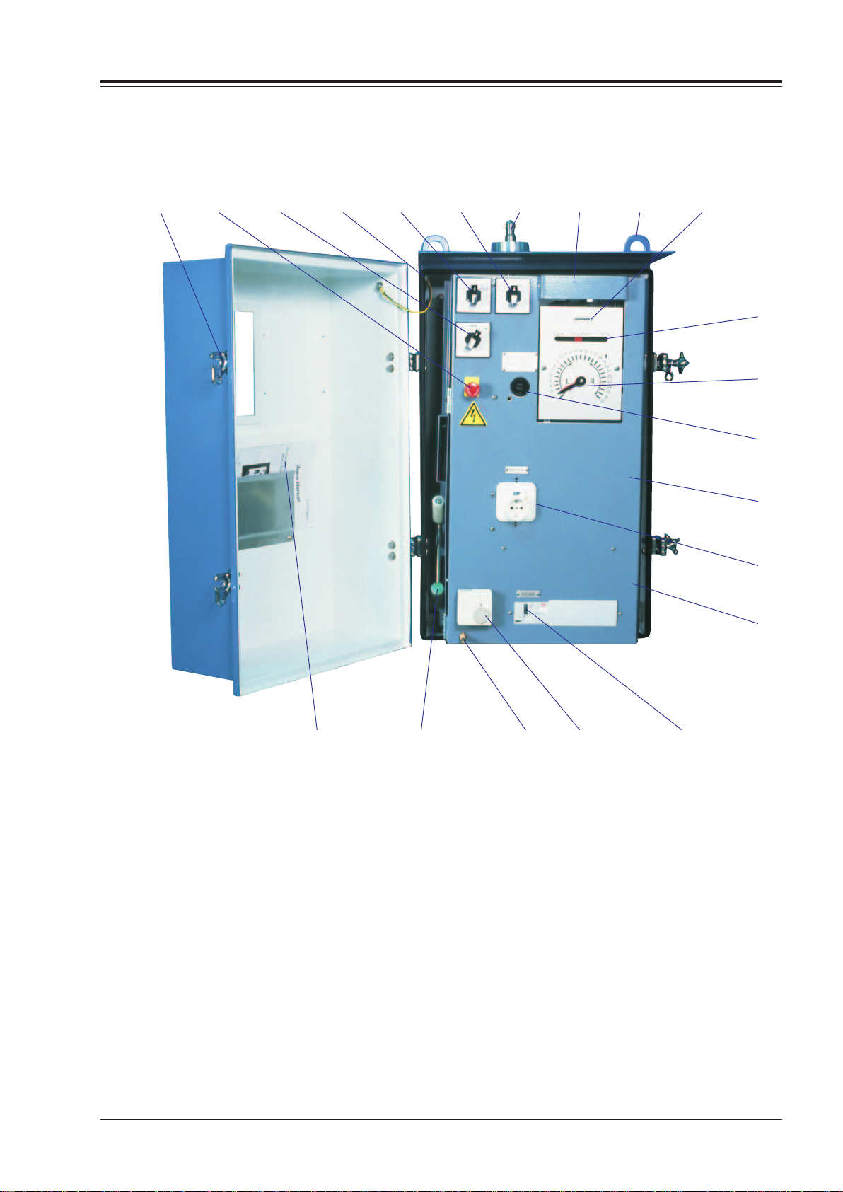
3 Checking of the motor and the counter
Open the motor-drive cabinet door and turn the selector-switch to the LOCAL position. Then turn the
control switch to the RAISE (LOWER) position.
Check that the motor works properly, the position indicator increases (decreases) one step, and the
counter advances one step for each operation. Record the counter’s value. The counter shows the
number of operations run by the on-load tap-changer (the overhaul schedule can be determined with
the help of this information).
Turn the control switch to the LOWER (RAISE) position. Check that the motor also works properly in
that direction, the position indicator decreases (increases) one step and the counter advances one step
more.
Reset the draghands.
4 Checking of the emergency stop
Give a RAISE or LOWER impulse and after about one second press the emergency stop. The operation
should be interrupted. Reset the emergency stop by turning the knob clockwise and set the protective
motorswitch to ON. The started operation should now be completed. Operate back to service position.

8
5 Checking of the earth fault protector (option)
If the motor-drive mechanism is equipped with an outlet, the earth fault protector should be tested by
pressing the test knob on the outlet on BUE or on the separate earth fault protector on BUL.
6 Checking of the heater
Disconnect the incoming auxiliary power.
WARNING
Beforestarting anyworkinsidethemotor-drivemechanism the auxiliary powermustbe switched off.
N. B. The motor, contactors and heating element may be energized from separate sources.
Open the control panel (BUE only).
Check by feeling with a finger on the protection plate that the heater has been functioning.
Close the control panel (BUE only). Reconnect the incoming auxiliary power.
Complete the inspection by turning the selector-switch to the REMOTE position and closing the
cabinet door.
7 Checking of the oil filter unit (option)
If the on-load tap-changer is equipped with an oil filter unit from ABB:
Read the pressure gauge.
Note the reading so the change from year to year can be seen.
If the pressure is 2.0 bar or more, or close to 2.0 bar, the filter insert should be replaced.
If moisture is suspected to have come into the on-load tap-changer compartment, the filter insert
should be replaced.
If a filter insert replacement is needed, call a specialist.
Also check for leakages. All leakages should be repaired!
Layout of on-load tap-changer
1. Bevel gears
2. Horizontal drive shaft with protective tubes
3. Oil valve
4. Pressure relay
5. Top section
6. Vertical drive shaft with protective tubes
7. Rating plate
8. Motor-drive mechanism
9. Diverter switch housing
10. Tap selector
12 13 4 5
9
10
6
7
8

9
Layout of motor-drive mechanism, type BUE
1. Locking device prepared for padlock
2. Emergency stop
3. (Option) Switch for extra heater
4. Air vent
5. LOCAL/REMOTEswitch
6. RAISE/LOWERswitch
7. Outgoing shaft
8. Lamp (40 W socket E27)
9. Lifting eye
10. Counter
11. Tap-change in progress indicator
12. Position indicator with draghands for max. and min.
position
13. Shaft for handcrank
14. Heater 50 W + optional 100 W (behind the panel)
15. (Option) Outlet with earth fault protector
16. Terminal blocks (behind the panel)
17. Protective motor switch
18. (Option) Thermostat or hygrostat for extra heater 100 W
19. Door-operated switch for lamp
20. Handcrank
21. Descriptions and circuit diagram
12345678910
21 20 19 18 17
11
12
13
14
15
16

10
Layout of motor-drive mechanism, type BUL
1. Position indicator with draghands for max. and
min. position
2. Tap-change in progress indicator
(Red = in progress, White = in position)
3. Counter
4. Outgoing shaft with multihole coupling half
5. Shaft for handcrank
6. Lifting eye
7. Locking device prepared for padlock
8. (Option) Multi position switches
9. (Option) Measuring amplifier
10. (Option) Switch for extra heater
11. (Option) Outlet
12. (Option) Earth fault protector (when outlet is installed)
13. Emergency stop
14. RAISE/LOWERswitch
15. LOCAL/REMOTEswitch
16. Protective motor switch
17. Air vent
18. Door operated switch for lamp
19. Terminal blocks
20. Hand lamp
21. Heater 50 W + optional 100 W
22. (Option) Thermostat or hygrostat for extra heater 100 W
23. Descriptions and circuit diagram
24. Handcrank
17 18 19 20 21 22 23 24
123456
7
8
9
10
11
12
13
14
15
16

11

1ZSE 5492-155 en, Rev. 1, 2000-01-15
ABBPowerTechnologiesAB
Components
Visitingaddress:Lyviksvägen10
Postaladdress:SE-77180Ludvika,SWEDEN
Tel.+46 240 78 20 00
Fax +46 240 121 57
E-mail:[email protected]
www.abb.com/electricalcomponents
Table of contents
Other ABB Industrial Equipment manuals
Popular Industrial Equipment manuals by other brands

Innovative Technology
Innovative Technology PureLab HE Glovebox user manual

ITEM
ITEM Linear Guide 6 60 PS Assembly guide

Graco
Graco 965660 Instructions and user guide

SSCOR
SSCOR DUET 2314 Series Operating Instructions & Maintenance Manual

Rittal
Rittal Top Therm SK 3126.4 Series Assembly instructions

Aerotech
Aerotech 2005759 Instructions for use manual