manuals.online logo
Brands
  1. Home
  2. •
  3. Brands
  4. •
  5. Esaote
  6. •
  7. Medical Equipment
  8. •
  9. Esaote MyLab User manual

Esaote MyLab User manual

ESAOTE
SAFETY AND STANDARDS
OPERATOR MANUAL
Rev.
C
September
2011
Doc # 29B05EN0 3
Introduction
This manual provides information on Safety and Standards for the MyLab product line.
This manual is organized in the following chapters:
Chapter 1: Operator Safety
This chapter describes the situations that could affect the operator safety when an
ultrasound system is used.
Chapter 2: Patient Safety
This chapter describes the situations that could affect the patient safety when an
ultrasound system is used.
Chapter 3: Standards
This chapter lists with which standards MyLab complies. It also lists with which
standards the peripherals connected to the device have to comply.
In this manual a WARNING pertains to possible injury to a patient and/or the
operator. A CAUTION describes the precautions, which are necessary to protect the
equipment. Be sure that you understand and observe each of the cautions and
warnings.
Table of Contents
1 - Operator Safety.............................................................................................1-1
Installation Requirements .......................................................................................1-1
Electrical Safety......................................................................................................1-1
Environmental Safety..............................................................................................1-2
Moving the Equipment ...........................................................................................1-2
Explosive Hazard....................................................................................................1-3
Transducers.............................................................................................................1-3
Biocompatibility and Infection Control ..................................................................1-4
Repetitive Strain Injury...........................................................................................1-4
Working with Video Display..................................................................................1-5
Safety Symbols .......................................................................................................1-5
2 - Patient Safety.................................................................................................2-1
Electrical Safety......................................................................................................2-1
Electromagnetic Compatibility ...............................................................................2-2
Biocompatibility and Infection Control ..................................................................2-2
Ultrasound Safety....................................................................................................2-3
Glossary and Definition of Terms.........................................................................2-12
3 - Devices Standards .........................................................................................3-1
Medical Device Directive .......................................................................................3-1
Medical Electrical Equipment Standard .................................................................3-1
Electromagnetic Compatibility ...............................................................................3-1
Biocompatibility .....................................................................................................3-1
Standards Summary Table ......................................................................................3-2
Acoustic Output ......................................................................................................3-2
Peripherals Standard Requirements ........................................................................3-2
M y L a b –S A F E T Y A N D S T A N D A R D
1-1
1 - Operator Safety
Installation Requirements
The “Getting Started” manual provides detailed instructions to correctly install and
connect your specific MyLab model. The same manual also contains all information
on the recommended peripherals that may be connected to the system.
If help is needed, ESAOTE personnel will be glad to provide you with the
necessary assistance to install your system.
Warnings
Incorrect installation of the system may cause operator hazard. Carefully follow the
MyLab “Getting Started” manual instructions for installing your device
Electrical Safety
The equipment label, placed on the rear panel, specifies the device electrical
requirements. Incorrect connections to the main power may compromise the
electrical safety of the system.
Warnings
Electrical shock hazard. Do not remove the system or the monitor
cover. Refer servicing and internal adjustments to qualified
ESAOTE personnel only.
Always turn the equipment off before cleaning it.
Cautions
To prevent further damage to your system and the accessories,
turn the unit’s power off if it does not start up correctly.
If your system incorporates an LCD, note that the screen is fragile
and must be treated accordingly.
Chapter
1
G
GS
S
W A R N I N G S
Observe the
following warnings
for maximum safety
C A U T I O N S
Observe these
precautions to
prevent damage to
your system
M y L a b –S A F E T Y A N D S T A N D A R D
1-2
Environmental Safety
Information about Reusing/Recycling
This symbol identifies a recyclable component. Depending on the dimensions of a
recyclable component, this symbol and the component’s material are printed on
the component by ESAOTE.
In this system, packing materials are reusable and recyclable; the unit and display
devices casings (plastic) and most of the cart components (plastic) are also
recyclable.
Refer to the MyLab “Getting Started” manual for any additional information on
special waste that has to be disposed of according to local regulations.
Exam Waste
Regard any exam waste as potentially infectious and dispose of it accordingly
Moving the Equipment
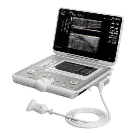
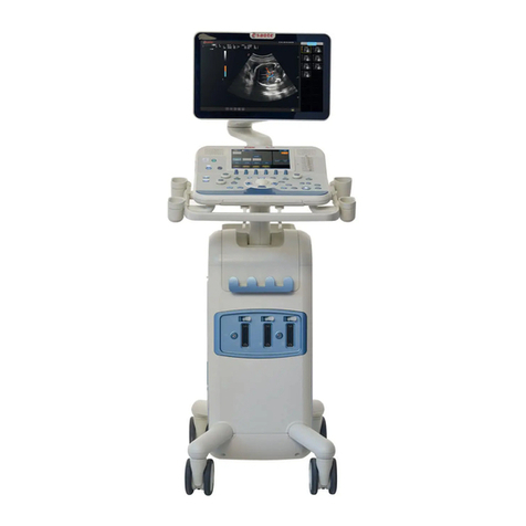
MyLab systems are designed to be easily moved by the operator. However the
equipment weight could require assistance during transportation. The MyLab
“Getting Started” manual details the weight and dimensions of your configuration.
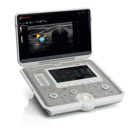
MyLab products can be classified as portable and mobile:
Portable means that the system is equipped with a handle, whose
size and weight allow it to be used to carry the system. The term
“portable” is always used with this meaning in these manuals.
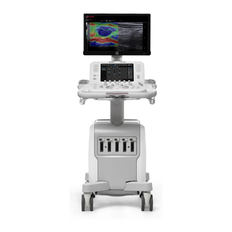
Amobile model or configuration is equipped with wheels
allowing to take the system from one room to another. The term
“mobile” is always used with this meaning in these manuals.
One can carry the console directly by its handle; observe the following precautions:
make sure the console is turned off,
if built-in, make sure the system display is secured prior to and
during transportation,
disconnect any cable or item (probes, ECG cable) attached to the
system,
should the console need to be put on the ground, lay it straight or
flat,
secure the system in a flat position if transporting it in a vehicle.
G
GS
S
G
GS
S
Portable
M y L a b –S A F E T Y A N D S T A N D A R D
1-3
The MyLab system complies with the EN60601-1: it is not unbalanced by a 10°
inclination. Observe the following precautions when transporting the system:
make sure the system is turned off,
unlock the cart’s wheels prior to moving the system,
avoid unnecessary shocks to the unit when rolling it over door
jambs or in and out of elevators,
when transporting the system with the probes attached, make sure
the cables are not dragging on the floor and that the probes are
properly positioned in the cart probe holder,
always use the handle to move the system. Never push the system
from its sides.
Observe the following precautions when transporting the system in a vehicle:
disconnect any cable or item (probes, ECG cable, …) attached to
the system and place the transducers in their cases,
a portable model should be packed in the original shipment case
(or other protective devices as available through ESAOTE) during
transportation,
for mobile systems, make sure the cart wheels are blocked and the
cart secured during transportation.
Explosive Hazard
The equipment is not suitable for use in the presence of a flammable anesthetic
mixture with air, oxygen or nitrous oxide. Do not use the system in the presence of
flammable anesthetics. Explosion is a hazard under such conditions.
Transducers
Use only ESAOTE approved transducers with the equipment. The MyLab
“Getting Started” manual lists which probes can be connected to the system.
MyLab “Advanced Operations” explains system related special features, when
applicable.
The “Transducers and Consumables” manual covers all aspects concerning
transducer cleaning and disinfecting.
Mobile
Configuration
Transportation in
Vehicle
W A R N I N G
G
GS
S
and
A
AO
O
T
TC
C
M y L a b –S A F E T Y A N D S T A N D A R D
1-4
Warnings
If you drop or strike a probe against another object, do not use it
until an electrical leakage current measurement test has
demonstrated that the electrical safety has not been compromised.
Do not immerse the entire transducer in liquid to clean it. The
transducer is not watertight and immersion may compromise the
electrical safety features of the probe.
Cautions
Never expose the probes to gas, heat or liquid sterilization
procedures. These methods can permanently damage the probe.
Do not connect or disconnect an active probe during live
scanning; the system must be in freeze mode or turned off to
connect or disconnect a probe.
Carefully follow the “Probes and Consumables” manual
instructions to clean or disinfect a probe.
Biocompatibility and Infection Control
Probes and electrodes intended to be used on intact skin have very limited
probabilities to propagate infections; basic procedures as described in the
“Transducers and Consumables” manual are sufficient for infection control.
Endocavity and transesophageal transducers require specific cleaning and
disinfecting procedures. See the “Transducers and Consumables” manual for
complete details on these procedures.
Repetitive Strain Injury
Musculoskeletal disorders have been reported by the clinical literature1 as a result of
repetitive scanning. These musculoskeletal disorders are also described by the term
Repetitive Strain Injury (RSI). To prevent the risk of RSI, it has been
recommended:
to maintain a balanced position while scanning,
not to grip the transducer with excessive force,
to take work breaks to allow your muscles to relax,
to introduce routine exercises such as gentle passive stretching.
1 Necas M. “Musculoskeletal symptomatology and Ripetitive Strani Injuries in Diagnostic Medical
Sonographers”, Journal of Diagnostic Medical Sonography 12, p. 266-273, 1996
Pike I, Russo A., Berkowitz J et al. “ the prevalence of musculoskeletal disorders among Diagnostic
Medical Sonographers”, Journal of Diagnostic Medical Sonography 13, p. 219-227, 1997
W A R N I N G S
Damage caused by
dropping a probe,
striking it against
another object,
pinching, kinking or
twisting the cable are
not covered under
warranty.
C A U T I O N S
Observe these
precautions to
prevent damage to
your system
T
TC
C
M y L a b –S A F E T Y A N D S T A N D A R D
1-5
Working with Video Display
Scanning can require long sessions in front of a display screen. Consequently visual
problems such as eyestrain and irritation can result2. Visual discomfort is reduced
when the following recommendations are observed :
orientate the display so that it can be comfortably observed while
scanning,
take rest breaks after a long scanning session.
Safety Symbols
The MyLab device uses the EN60601-1 safety symbols for medical electronic
devices to classify a connection or to warn of any potential hazards.
On (power)
Off (power)
Type CF applied part (suitable for cardiac application)
Type B applied part
Type BF applied part
Equipotentiality
High Voltage
This symbol generically means "Attention". Read carefully the
appropriate sections of user manuals before using any function
labeled with this symbol.
IP68
The footswitch is watertight.
2 See for example OSHA 3092 “Working safely with video terminals display” 1997
M y L a b –S A F E T Y A N D S T A N D A R D
1-6
M y L a b –S A F E T Y A N D S T A N D A R D
2-1
2 - Patient Safety
Electrical Safety
Warnings
The system must be properly grounded to prevent shock hazards.
Protection is provided by grounding the chassis with a three-wire cable
and plug; the system must also be powered through a properly
grounded receptacle.
Do not replace the system fuses with types different from those
specified by the MyLab “Getting Started” manual.
Mobile configurations provide insulated plugs and connectors to
manage optional hard copy devices (VTR, printers). Follow the
instructions in the “Getting Started” manual to install such a device.
Incorrect connections may compromise the electrical safety of the
system.
If the Operator plans to use hard-copy devices with a portable model,
and one plans to utilize hard-copy devices, read and carefully follow
the instructions in the “Getting Started” manual to install such devices.
Incorrect connections or use of peripherals with improper safety
characteristics may compromise the electrical safety of the system.
MyLab models are not watertight and provides a class IP(X)0 degree of
protection to liquids; do not expose the system to rain or moisture.
Avoid placing liquid containers on the system.
Remove probes and electrocardiography leads from patient contact
before applying a high voltage defibrillation pulse.
MyLab systems use high frequency signals. Pacemakers could interfere
with these signals. The user should be aware of this minimal potential
hazard and immediately turn the unit off if interference with the
pacemaker operation is noted or suspected.
While using the system in combination with high frequency devices
(like electro-surgical units), be aware that a failure in the surgical device
or a damage to the transducer lens can cause electro-surgical currents
that can burn the patient. Thoroughly check the system and the probe
Chapter
2
W A R N I N G S
Observe the
following warnings
for maximum safety
G
GS
S
M y L a b –S A F E T Y A N D S T A N D A R D
2-2
before applying HF surgical currents to the patient. Disconnect the
probe when not imaging
Electromagnetic Compatibility
Ultrasound systems require special precautions regarding EMC and must be
installed and put into service according to the provided information.
Ultrasound units are designed to generate and receive radiofrequency (RF) energy
and are, therefore, susceptible to other RF sources. As an example, other medical
devices, information technology products or TV/radio transmitters may cause
interference with the ultrasound system.
In the presence of RF interference, the physician must evaluate the image
degradation and its diagnostic impact.
Warnings
Portable and mobile RF communication equipment may cause
interference with the ultrasound system. Do not use these devices in
the vicinity of ultrasound equipment.
Use of accessories and cables other than those specified in the MyLab
“Getting Started” manual may result in increased emission or
decreased immunity of the system.
If an ultrasound system causes interference (This can be identified by turning the
system off and on) with other devices, the user could try to solve the problem by:
relocating the system,
increasing the separation from other devices,
powering the ultrasound system from an outlet different from the one
of the interfering device,
contacting ESAOTE Service personnel for help.
Ele ctr o-S u rgi c al U n it s (ES Us )
Electro-surgical units or other devices that introduce radiofrequency
electromagnetic fields or currents into the patient may interfere with the ultrasound
image. An electro-surgical device in use during ultrasound imaging will grossly
affect the 2D image and render Doppler modalities useless.
Biocompatibility and Infection Control
Before each exam properly clean the probes. Refer to the “Transducers and
Consumables” manual for further details on cleaning and disinfecting probes, kits
and electrodes.
Sensitivity to
interference is more
noticeable in Doppler
modes.
W A R N I N G S
G
GS
S
The “Getting
Started” manual
provides the table for
equipment distance
requirements.
T
TC
C
M y L a b –S A F E T Y A N D S T A N D A R D
2-3
Items in Contact with Patient
ESAOTE probes and electrodes materials that are in contact with the patient have
been proved to comply with EN ISO 10993 “Biocompatibility Tests
Requirements”, according to their intended use. No negative reactions to these
materials have been reported.
Latex Sensitive Patient
The USA Food and Drug Administration (FDA) has issued an alert on products
composed of latex, because of reports of severe allergic reactions.
Note
ESAOTE probes and electrodes do NOT contain latex.
The transducer protective covers used during the patient exam are usually
composed of latex. Carefully read the protective cover package labeling to verify
the material used. Be certain to identify latex sensitive patients prior to the exam.
Serious allergic reactions to latex have been reported and the user should be ready
to react accordingly.
Ultrasound Safety
Introduction
ESAOTE has adopted the more recent requirements and recommendations
established by the USA Food and Drug Administration and by the American
Institute of Medicine and Biology. MyLab is equipped with the Acoustic Output
Display feature to provide the user with real-time, on-line information on the
actual power of the system. The following sections describe the rationale of this
methodology. ESAOTE recommends the use of the ALARA principle (see
below), which is extensively covered in this manual.
Clinical Safety
In the USA, in more than three decades of use, there has been no report of injury
to patients or operators from medical ultrasound equipment.
American Institute for Ultrasound in Medicine (AIUM)
Statement on Clinical Safety: October 1982, Revised March
1983, October 1983 and March 1997.
Diagnostic ultrasound has been in use for over 25 years. Given its
known benefits and recognized efficacy for medical diagnosis,
including use during human pregnancy, the American Institute of
Ultrasound in Medicine herein addresses the clinical safety of such
use:
W A R N I N G
MyLab “Operator
Manual CD”
provides data about
the acoustic power
levels.
Refer to the glossary
at the end of this
chapter for specific
terms.
M y L a b –S A F E T Y A N D S T A N D A R D
2-4
No confirmed biological effects on patients or instrument operators caused by
exposure at intensities typical of present diagnostic ultrasound instruments have
been reported. Although the possibility exists that such biological effects may be
identified in the future, current data indicate that the benefits to patients deriving
from the prudent use of diagnostic ultrasound outweigh the risks, if any, that may
be present.
The ALARA (AsLow AsReasonably Achievable) principle is the guideline for
prudent use: during an exam, the user should use for the shortest duration the least
amount of acoustic output to obtain the necessary clinical information for
diagnostic purposes.
Ultrasound Bioeffects
Although diagnostic ultrasound has an excellent history of safety, it has been
known for a long time that ultrasound, at certain levels, can alter biological systems.
The AIUM Bioeffects Committee describes two fundamental mechanisms by
which ultrasound may induce biological effects: non-thermal or mechanical
mechanisms1 and thermal effects.
Non-thermal bioeffects, also referred to as mechanical bioeffects, seem to be
caused by the tissue alternate expansion and contraction induced when ultrasound
pressure waves pass through or near gas. The majority of these non-thermal
interactions, also known as cavitation, deal with the generation, growth, vibration,
and possible collapse of microbubbles within the tissue. The occurrence of
cavitation depends on a number of factors, such as the ultrasonic pressure and
frequency, the ultrasonic field (focused or unfocused, pulsed or continuous), the
nature and state of the tissue and boundaries. Mechanical bioeffects are a threshold
phenomenon, occurring only when a certain level of output is exceeded. However,
the threshold level varies depending on the tissue. The potential for mechanical
effects is thought to increase as peak rarefactional pressure increases, but to
decrease as the ultrasound frequency increases.
Although there have been no adverse mechanical bioeffects in humans from
diagnostic ultrasound exposure, it is not possible to specify thresholds at which
cavitation will occur in mammals.
Thermal bioeffect is the rise in temperature of tissue when exposed to acoustic
energy. The acoustic energy is absorbed by body tissue; absorption is the
conversion of this energy into heat. If the rate of energy deposition in a particular
region exceeds the ability to dissipate the heat, the local temperature will rise. The
rise in temperature will depend on the amount of energy, the volume of exposure,
and the thermal characteristics of the tissue.
1 American Institute of Ultrasound in Medicine Bioeffects Committee, Bioeffects Considerations for the
Safety of Diagnostic Ultrasound, J. Ultrasound Med., 1988, 7 Suppl.
M E C H A N I C A L
B I O E F F E C T S
“Cavitation” phenomenon
T H E R M A L
B I O E F F E C T
Rise in temperature of
tissue exposed to acoustic
energy.
M y L a b –S A F E T Y A N D S T A N D A R D
2-5
On-screen Real-Time Acoustic Output Display
Until recently, application-specific output limits2 established by the USA Food and
Drug Administration (FDA) and the user's knowledge of equipment controls and
patient body characteristics have been the means of minimizing exposure. Now,
more information is available through a new feature, named the Acoustic Output
Display. The output display provides users with information that can be specifically
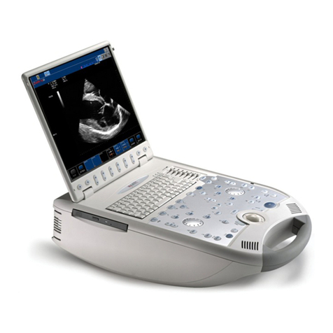
applied to ALARA. It eliminates some of the guesswork and provides both an
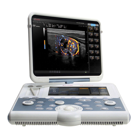
indication of what may actually be happening within the patient (i.e. the potential
for bioeffects), and what occurs when system control settings are changed. This
makes it possible for the user to get the best image possible while following the
ALARA principle and thus to maximize the benefits/risks ratio.
MyLab incorporates a real-time acoustic output display according to the
AIUM3/NEMA4 "Standard for Real-Time Display of Thermal and Mechanical
Acoustic Output Indices on Diagnostic Ultrasound Equipment" publication,
adopted in 1992 by both institutions. This output display standard is intended to
provide on-screen display of these two indices, which are related to ultrasound
thermal and cavitation mechanisms, to assist the user in making informed risk (i.e.
patient exposure)/benefit (diagnostically useful information) decisions.
Considering the type of exam, patient conditions and the case study level of
difficulty, the system operator decides how much acoustic output to apply for
obtaining diagnostically useful information for the patient; the thermal and
mechanical indices real-time display is intended to provide information to the
system operator throughout the examination so that exposure of the patient to
ultrasound can be reasonably minimized while maximizing diagnostic information.
For systems with an output display, the FDA currently regulates only the
maximum output. MyLab system has been designed to automatically default the
proper range of intensity levels for a particular application. However, within the
limits, the user may override the application specific limits, if clinically required.
The user is responsible for being aware of the output level that is being used. The
MyLab real-time output display provides the user with relative information about
the intensity level.
The Mechanical Index
The Mechanical Index (MI) is defined as the peak rarefactional pressure in MPa
(derated by a tissue attenuation coefficient of 0.3 dB/cm/MHz) divided by the
square root of the probe central frequency in MHz.
With the MI, the user can keep the potential for mechanical bioeffects as low as
reasonably achievable while obtaining diagnostically adequate images. The higher
the index, the larger the potential. However, there is not a level to indicate that
2 Also known as the preamendments limits, those values were established on the basis of acoustic output
of equipment on the market before 1976.
3 American Institute for Ultrasound in Medicine.
4 National Electric Manufacturers Association.
O D S
Thermal and Mechanical
Indices display to assist in
making informed
risk/benefit decisions
M I
Estimates mechanical
bioeffects
M y L a b –S A F E T Y A N D S T A N D A R D
2-6
bioeffect is actually occurring: the index is not intended to give an "alarm" but to
use it to implement the ALARA principle.
The Thermal Index
The purpose of the Thermal Index (TI) is to keep the user aware of conditions that
may lead to a temperature rise under certain defined assumptions. It is the ratio
between the total acoustic power to the power required to raise tissue temperature
by 1°C, estimated on thermal models. There are currently three thermal indices
(each based on a specific thermal model) used to estimate temperature rise whether
at the surface, within the tissues, or at the point where the ultrasound is focusing
on bone:
1. The Soft Tissue Thermal Index (TIS) provides information on
temperature increase within soft homogeneous tissue.
2. The Cranial Bone Thermal Index (TIC) indicates temperature increase
of bone at or near the surface, as may occur during a cranial exam.
3. The Bone Thermal Index (TIB) provides information on temperature
increase of bone at or near the focus after the beam has passed
through soft tissue.
As with the Mechanical Index, the thermal indices are relative indicator of
temperature rise: a higher value represents a higher temperature rise; they indicate
that the possibility for an increase in temperature exists and they provide a relative
magnitude that can be used to implement ALARA.
Acoustic Output Display
The acoustic output indices are displayed during live scanning to the right of the
screen, together with the transmit power setting.
The following abbreviations are used:
Index
Abbreviation
Soft Tissue Thermal Index
TIS
Cranial Bone Thermal Index
TIC
Bone Thermal Index
TIB
Mechanical Index
MI
The output display is organized to provide meaningful information to implement
ALARA without "distracting" the user with unnecessary data. During the entry of
the patient ID, the user is provided with a choice of applications (Cardio, Vascular,
OB, etc.); depending on the selection, the system will default the appropriate
indices.
Note
Index values below 0.4 are NOT displayed by this system.
To optimize ALARA, index values equal or higher than 0.4 are
displayed even if the maximal index value does not exceed 1.0.
T I
Relates to temperature rise
Indices are displayed
in 0.1 increments.
M y L a b –S A F E T Y A N D S T A N D A R D
2-7
The Output Display
The following table shows the indices used for each clinical application. Indices are
displayed in 0.1 increments.
Application
MI
TIS
TIB
TIC
OB/Fetal
Yes
Yes
Yes
No
Neonatal
5
Yes
Yes
Yes
Yes
Adult Cephalic
Yes
Yes
No
Yes
All others
Yes
Yes
Yes
6
No
The Output Default Settings
System default settings depend upon the probe, the mode of operation and the
application which is selected during the patient ID procedure. The MyLab defaults
the transmit power to obtain output levels that are below the historic Ispta limits
established by the FDA for the selected application.
Methodology and Accuracy of Display
The displayed indices values must be interpreted as relative information to help the
user to achieve the ALARA principle.
Initial data are derived from laboratory measurements based on the AIUM
standard. Then the indices are calculated beginning from these measurements
according to the AIUM/NEMA "Standard for Real-Time Display of Thermal and
Mechanical Acoustic Output Indices on Diagnostic Ultrasound Equipment"
publication. Many of the assumptions used for measurements and calculation are
conservative in nature. The measured water tank values are derated using the
conservative attenuation coefficient established by the standard (0.3
dB/cm/MHz). Over-estimation of actual in-situ exposures is thus part of the
calculation process.
Accuracy: 14% for the MI, 30% for the TI A number of factors influence the
estimation of the accuracy of the displayed indices, the most significant ones being
the variability between probes and the laboratory measurements accuracy
(hydrophone, operator, algorithms, etc.) itself, while variability of the system pulser
and efficiency is a minor contributor.
The accuracy estimate, based on the variability range of probes and systems, and
on the inherent modeling and measurements errors, is 14% for the MI and 30%
for TI indices; this accuracy estimate does not consider errors in/or caused by
measuring with the AIUM standard.
5 Includes Neonatal Head studies
6 Only when TIB≠TIS
In combined modes
(ex.: 2D+Doppler),
the indices will show
the highest value
between the two
modes.
I N D I C E S
ACCURACY
M y L a b –S A F E T Y A N D S T A N D A R D
2-8
Maximum Acoustic Output
This system does not use the historic FDA limits for Isppa and Imax, but rather
the recently adopted MI, which is now considered a better relative indicator of
non-thermal bioeffect mechanisms. The maximum MI is below 1.9 (see the
“Getting Started” manual for your model actual maximum); the FDA has
recognized this value as equivalent to preamendments Isppa limits. The maximum
output for Ispta is limited to the preamendments FDA limit for peripheral vascular
applications (720 mW/cm2).
Other application limits have been established as per this table:
Application
Preamendments Ispta
Limits (mW/cm2)
MyLab Maximum
(mW/cm2)
OB/Fetal
94
430
Cardiac
430
720
Pediatric
94
430
Peripheral Vascular
430
720
Other
94
720
The maximum output for a given probe can be less than the system limit, since the
maximum depends on various elements (crystal efficiency, mode of operation, …).
Acoustic Output Controls
Control features may be divided into three categories:
1. controls which directly affect the intensity (direct controls)
2. controls which indirectly affect the intensity (indirect controls)
3. controls, which do not affect the intensity, such as the gains and the
processing curves.
Co n tr ols W hich D ir ec t ly Af f ec t th e In te n sity
This category includes two system controls:
the application selection, which establishes the appropriate range of
intensities (see maximum output section); the application also
establishes the indices to be displayed;
the POWER control, which allows an increase or decrease in the
output intensity within the range of the selected application. This
parameter will affect both the MI and the TI values.
Co n tr ols W hich I n dir e ct l y Aff e ct th e In te n si ty
This category includes controls, which change several aspects of the transmitted
ultrasonic field rather than the intensity. Intensity is affected because of the field
variations. Each mode has its own pulse repetition frequency (PRF) and intensity
level; moreover, for each mode, a number of parameters will indirectly affect the
transmitted field.
M A X I M U M
O U T P U T
MI < 1.9
Ispta<720 mW/cm2
D I R E C T
C O N T R O L S
the Application
the POWER
I N D I R E C T
C O N T R O L S
PRF
Focal Point
Frequency
CFM Process
Sample Volume
M y L a b –S A F E T Y A N D S T A N D A R D
2-9
Note
The TI index display depends on the application and on the mode.
The MI may increase whenever the PRF is decreased, i.e. when the field of view is
increased.
MyLab allows the user to set the transmit focal point which will affect both indices
by varying the beam profile. Generally, higher MI's and TI's will occur with closer
focal points. If more than one transmit focal point is activated, MI and TI values
will each correspond to the zone with the largest value. In addition, all system
probes can image at two frequencies; both indices are usually different, depending
on the probe bandwidth.
The same controls described for 2D affect the acoustic output. Because the tissue
response is a non-linear phenomenon, this modality usually requires higher
acoustic outputs than conventional imaging. While using this mode, the MI is
your primary concern; a deeper transmit focal point helps to keep the MI value as
low as possible.
In M-Mode, the transmitted field is only affected by the transmit focal point and
the frequency. If M-Mode is displayed with 2D and the 2D is updated, the system
may show the latter mode MI (and TI if available) if higher.
The MI is primarily dependent on 2D settings, i.e. the depth (which will determine
the 2D and color PRF) and the transmit focal point. The MI may also be increased
by a decrease in the color PRF.
The TI may be increased by increasing the color CFM. Increasing the color frame
rate may increase the TI while decreasing the MI. Finally, probes can provide color
at two frequencies; the outcome in terms of transmitted field is marginal and
largely unpredictable.
This mode optimizes CFM settings in order to image the movement of tissue, thus
the same controls described for 2D-CFM affect the acoustic outputs.
In PW, the sample volume depth automatically sets the Doppler PRF and the focal
point. Deeper sample volumes will cause lower PRF; the MI may, however, not
increase since the focal point is far, while the TI is generally reduced. The TI may,
however, change if the sample volume size is varied. This factor accounts generally
for a MI modification.
TV Doppler optimizes your settings to analyse tissue motion.
Finally, most probes provide Doppler at two frequencies; the outcome in terms of
transmitted field is marginal and largely unpredictable.
2D
TEI
M-Mode
2D-CFM
TVM
Pulsed Wave
Doppler
TV
M y L a b –S A F E T Y A N D S T A N D A R D
2-10
In CW, the only "variable" factor is the Doppler frequency. As stated before, most
probes provide Doppler at two frequencies; the outcome in terms of transmitted
field is marginal and largely unpredictable. The user can vary the spectral velocity
range; this does NOT, however, change the system’s PRF.
Note
In Doppler modes, if the tracings are displayed with an updated 2D,
the 2D values are used if higher than the Doppler indices.
Implementing ALARA with MyLab
Prudent use implies that during an exam the user should use for the shortest time
the least amount of acoustic output to obtain the necessary clinical information for
diagnostic purposes. In other words, the goal is to keep the TI and the MI indices
as low as possible for the shortest time while obtaining the necessary clinical
information.
This section does not cover the patient and technique factors, which may influence
the indices such as the patient body size, the tissue perfusion characteristics, the
presence or the absence of fluid, etc.
Select the appropriate Application when you enter the patient data.
Depending on the patient characteristics and the type of exam (see
Intended Use Section) select the appropriate probe and frequency.
Use the system capabilities to preset the MyLab system to default each mode
according to your needs or specific applications; this will reduce the need for real-
time interactions and help to obtain useful images quickly thus reducing ultrasound
exposure.
Start scanning with a low output level and optimize the focusing, the
gains and all other system adjustments; if this is not adequate for
diagnostic purposes, then increase the output level. In cardiac studies,
use Tissue Enhancement Imaging if acoustic noise is affecting the
images’ readability.
Use the output display feature to guide your settings; remember that
the indices do not consider TIME exposure: the higher your indices,
the shorter the patient exposure should be.
Wh ic h In d ex W hen
In cardiac,vascular and general purpose (abdominal,small parts,
musculoskeletal) exams, the system displays the TIS in addition to the MI. In
imaging and CFM modes, the primary concern is in keeping the "cavitation"
predictor as low as possible. You can minimize the MI by reducing the power to
the lowest possible level, and adjusting the TGC and general gain controls. Use the
transmit focal point to enhance resolution and sensitivity in the area of interest: this
Continuous Wave
Doppler
ALARA Guidelines
G
GS
S
See the “Getting
Started” manual for
your system controls.
In cardiac, vascular,
abdominal and small
parts examinations,
MI is the primary
concern in imaging
modes, while the TIS
is the principle index
in Doppler.

Other Esaote Medical Equipment manuals

Esaote 6420 Series User manual

Esaote

Esaote 6420 Series User manual

Esaote MyLab SIGMA User manual

Esaote

Esaote MyLab SIGMA User manual

Esaote MyLab 9 User manual

Esaote

Esaote MyLab 9 User manual

Esaote MyLabX8 User manual

Esaote

Esaote MyLabX8 User manual

Esaote MyLabOmega User manual

Esaote

Esaote MyLabOmega User manual

Esaote MyLabOmegaVET User manual

Esaote

Esaote MyLabOmegaVET User manual

Esaote MyLabX75VET User manual

Esaote

Esaote MyLabX75VET User manual

Esaote MyLab 9VET User manual

Esaote

Esaote MyLab 9VET User manual

Esaote O-scan Series User manual

Esaote

Esaote O-scan Series User manual

Esaote MyLabX5VET User manual

Esaote

Esaote MyLabX5VET User manual

Esaote MyLabX7VET User manual

Esaote

Esaote MyLabX7VET User manual

Esaote MyLabX6 User manual

Esaote

Esaote MyLabX6 User manual

Esaote mylab 30 gold User manual

Esaote

Esaote mylab 30 gold User manual

Esaote MyLabSigma elite User manual

Esaote

Esaote MyLabSigma elite User manual

Esaote MyLabGamma User manual

Esaote

Esaote MyLabGamma User manual

Esaote MyLab X75VET User manual

Esaote

Esaote MyLab X75VET User manual

Esaote MyLab40 User manual

Esaote

Esaote MyLab40 User manual

Esaote MyLab SigmaVET User manual

Esaote

Esaote MyLab SigmaVET User manual

Esaote MyLabX75 Series User manual

Esaote

Esaote MyLabX75 Series User manual

Esaote MyLab X8 User manual

Esaote

Esaote MyLab X8 User manual

Esaote MyLabDelta User manual

Esaote

Esaote MyLabDelta User manual

Esaote MyLabX8VET User manual

Esaote

Esaote MyLabX8VET User manual

Esaote MyLabX9 User manual

Esaote

Esaote MyLabX9 User manual

Popular Medical Equipment manuals by other brands

Getinge Servo-u Cleaning Training

Getinge

Getinge Servo-u Cleaning Training

Organ recovery systems LifePort Kidney Transporter LKT201 Instructions for use

Organ recovery systems

Organ recovery systems LifePort Kidney Transporter LKT201 Instructions for use

Wissner-Bosserhoff Linet ProphyCair User manual and technical description

Wissner-Bosserhoff

Wissner-Bosserhoff Linet ProphyCair User manual and technical description

Dermlite Lumio 2 manual

Dermlite

Dermlite Lumio 2 manual

Otto Bock 757B35-1 Instructions for use

Otto Bock

Otto Bock 757B35-1 Instructions for use

DJO AirCast AirSelect Short manual

DJO

DJO AirCast AirSelect Short manual

Bort ImmoXpress 145 300 quick start guide

Bort

Bort ImmoXpress 145 300 quick start guide

Dräger WBR82 Instructions for use

Dräger

Dräger WBR82 Instructions for use

Norma Face Shield instructions

Norma

Norma Face Shield instructions

Mid America Motorworks CP Relief WandCP 1000 Operation manual

Mid America Motorworks

Mid America Motorworks CP Relief WandCP 1000 Operation manual

ResMed Sullivan Comfort operating manual

ResMed

ResMed Sullivan Comfort operating manual

LiteGait 300 Series Assembly instructions

LiteGait

LiteGait 300 Series Assembly instructions

NRS F19467 User instructions

NRS

NRS F19467 User instructions

laerdal Resusci Baby QCPR user guide

laerdal

laerdal Resusci Baby QCPR user guide

Norco Eco-Stim NC89481 instruction manual

Norco

Norco Eco-Stim NC89481 instruction manual

ResMed AirFit F30 user guide

ResMed

ResMed AirFit F30 user guide

Gima CMS80 user manual

Gima

Gima CMS80 user manual

ResMed AIRCurve 10 S user guide

ResMed

ResMed AIRCurve 10 S user guide

manuals.online logo
manuals.online logoBrands
  • About & Mission
  • Contact us
  • Privacy Policy
  • Terms and Conditions

Copyright 2025 Manuals.Online. All Rights Reserved.