EsiWelma Sensigas ESN F Series User manual

EsiWelma s.r.l.
rev. 00 of 01-09-10 / pg. 1
ESN.F.D.._en
Carbon dioxide (CO2) detectors
for homes, recreational vehicles, workplaces and
more in general, in public or private places with a
high concentration of people.
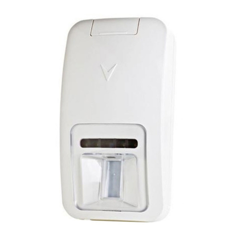
ESN.F.D..
__________________________________________________________________________________________
Electronic microprocessor Carbon Dioxide (CO
2
) detectors
Display of carbon dioxide measurement in addition to ambient temperature, relative humidity and the
operational status of the detector, on large LCD screen
NDIR (nondispersive infrared) carbon dioxide detection technology ABC Logic™ self-calibration system
(automatic calibration)
Measuring range 0…20,000 ppm of CO2 (other ranges on request)
Power supply 230Vac, 115Vac, 24Vac/dc (see models)
Relay command output with potential-free contact (SPST 230Vac / 3A, or 30Vdc / 3A), suitable for any
command or alarm device.
Optional measurement outputs 4…20mA or 0…10Vdc (see models)
__________________________________________________________________________________________
Use
The ESN.F.D.. detectors can be used to measure the concentration of Carbon Dioxide and
to command transmitters or actuating devices where there are abnormal concentrations well
below the gas hazard threshold.
The ESN.F.D.. detectors can also be used to monitor Carbon Dioxide as an indication of the
quality of the air in hotels, offices, exhibition centres, shops, restaurants, schools, conference
rooms, cinemas, theatres and ventilation systems in general.
__________________________________________________________________________________________
Operation
At the end of the warm-up phase, during which the detector is inactive, it enters normal
operation mode, and will continue in this state until it detects gas.
When the gas
concentration exceeds the threshold set-points, the detector senses its presence and goes
into the alarm condition indicated by the activation of the relay and by the relative display
symbol coming on.
250...…350 ppm level of the air in outdoor environment (normal)
350...…1000 ppm typical level found in living spaces with good air circulation
1000…...2000 ppm level associated with drowsiness and lack of air
2000…...5000 ppm level associated with headache, drowsiness and stale, stagnant air like
a closed room. This could cause lack of concentration, loss of atten-
tion, increased heartbeat and slight nausea
> 5000 ppm exposure could lead to a serious lack of oxygen resulting in brain da-
mage, coma and death.
__________________________________________________________________________________________
Power supply
Outputs
230Vac
115Vac
24Vac/dc
SPST relay ESN.F.D.A.R ESN.F.D.D.R ESN.F.D.E.R
SPST relay + 4...20mA ESN.F.D.A.I ESN.F.D.D.I ESN.F.D.E.I
SPST relay + 0...10Vdc ESN.F.D.A.V ESN.F.D.D.V ESN.F.D.E.V
For special versions, please contact Customer Service.
__________________________________________________________________________________________
Levels of CO2
and effects on
humans
Available
models
and ordering
information

EsiWelma s.r.l.
rev. 00 of 01-09-10 / pg. 2
__________________________________________________________________________________________
Carefully read the instructions and electronic connection diagrams in this document and follow them to the
letter. Keep this document in a safe place for future consultation.
The device must be installed by qualified technicians.
Installation guidelines
The detector must be installed (See also fig. 1, step 1):
Since Carbon Dioxide is heavier than air, it will be concentrated close to the floor. This device has a display
screen, so if it is positioned too low it would not be easy to use; we suggest installing it about 1.2-1.3m from
the floor.
The detector must not be installed (See also fig. 1, step 2):
• exposed to direct sunlight or outdoors
• near stoves and cooking appliances
• near sinks and taps
• near exhaust hoods, windows, fans etc.
• in areas where dirt and/or dust can clog the bottom and side grille of the detector
• where the temperature or humidity exceeds the detector's operating limits
• in closed spaces (behind curtains, inside cupboards etc.).
Installation
Install the detector as follows (See also fig. 1, steps 3-6):
Use the tip of a screwdriver to lightly push down the side tabs of the detector until the wall mounting plate is
separated from the detector body
Fix the mounting plate to the wall with the screws supplied or a suitable wall bracket, or to the recessed
mounting cabinet used.
Connect the wiring on the wall mounting plate as shown in the connection diagram (Fig.2) in Electrical
Installation
Remount the detector body onto the wall-mounting plate; make sure the tabs click into place.
__________________________________________________________________________________________
Installation and
Commissioning
Fig. 1

EsiWelma s.r.l.
rev. 00 of 01-09-10 / pg. 3
__________________________________________________________________________________________
Electrical Installation
Make sure the wiring conforms to the standards in
force.
The devices must be connected to the mains power
supply and remain permanently powered.
Omnipolar disconnection must be included in the
mains.
Some possible wiring diagrams:
Example a): - Command of an audible alarm from a
detection point.
Example b): - Command of a visual alarm from
several detection points.
Operator interface
Commissioning Power-up the detector by holding the (power) button pressed for about 2 seconds and check that the display
shows the measurements in the format as above.
To select the threshold set-points and the set-points for all the other parameters, first press the selection
(switch) and then the (up) and (down) buttons to set the value for each one.
The set-points can only be changed if its value is flashing; to rapidly increase the set-points, hold the (down)
or (up) button pressed for more than 3 seconds.
After selecting and changing the set-points and any other parameters, lock them in so they are not
accidentally changed by pressing the (down) and (up) buttons together and holding them down for more than
5 seconds; the set-points are locked in when the display shows this symbol .
To restore the possibility of changing set-points, once more press down on the (down) and (up) buttons at the
same time; the set-points can be changed when the display no longer shows this symbol .
Carry out an operational test using a CO
2
gas canister with dosage valve; release a small amount of gas
close to the grille below and control the correct engagement of the command and/or alarm device connected
to the relay as well as the appearance on the display of the symbol .
It is advisable to repeat the operational test at least once a year, or after a prolonged period of stoppage.
If other test methods are used instead of the one described the detector may generate different, unexpected
responses. In particular, the use of inappropriate substances or vapours (alcohol or silicon-based solvents
etc.) or in any case, high concentrations of test gases could cause permanent damage to the sensing element
and may cause the detector to operate incorrectly.
The detector needs no periodic maintenance, with the exception of the periodic operational test and its repla-
cement 15 years after the installation date.
__________________________________________________________________________________________
230Vac or 115Vac or 24Vac/dc
a)
1 (L)
2 (N)
ESN.F.D..
7 (C)
6 (NO)
230Vac or 115Vac or 24Vac/dc
b)
1 (L)
2 (N)
ESN.F.D..
7 (C)
6 (NO)
1 (L)
2 (N)
ESN.F.D..
7 (C)
6 (NO)
Power On/Off
Down
(Decrease)
Up
(Increase)
Select
(Switch)
Humidity Temperature
Lock Set
point data
Status
of relay
Carbon Dioxide

EsiWelma s.r.l.
rev. 00 of 01-09-10 / pg. 4
__________________________________________________________________________________________
Please note that the in terms of measuring the level of CO
2
, the detector will reach maximum precision after
14 days of uninterrupted operation of the device following installation or a long period of stoppage (several
months).
Still, acceptable precision is achieved after two days of operation, in other words after the first full calibration
cycled according to the ABC Logic™ self-calibration system algorithm.
In order to obtain maximum precision, during the calibration period following installation (or long period of
stoppage) do not expose the detector to high quantities of CO2, for example the ongoing presence of many
people in the premises where the detector is installed.
Use a permanent marker to write the replacement date of the detector on the plate provided and place it in a
visible position (after installation is completed).
Use a wet cloth and mild detergent to periodically clean the device.
Do not use aggressive detergents like alcohol, ammonia, solvents etc.
Before cleaning the detector, switch off the system power supply to avoid the risk of electric shock.
Warning The detector and its sensing element have been designed for ongoing use in areas where there is permanent
occupation by people, so normally pollution-free.
The presence of gases or vapours from some aggressive substances such as alcohol, silicons or solvents
found in some detergents or polishes, or from the fumes generated by cooking or also an excess of steam,
may cause inappropriate action of the detector and in the long term could affect the reliability of the device.
__________________________________________________________________________________________
__________________________________________________________________________________________
__________________________________________________________________________________________
Technical
specifications
Power supply (see models) 230Vac
±
10% or 115Vac
±
10% or 24Vac/dc
±
10%
Frequency / Consumption 50/60Hz / 3.5W maximum, 2.5W average
Sensing element
CO
2
Temperature
Relative humidity
• NDIR (nondispersive infrared)
• NTC thermistor
• Capacitive sensor series HS
Measuring range
CO
2
Temperature
Relative humidity
• 0...20.000ppm (other ranges on request)
• 0…50°C
• 0...99% RH
Measuring precision (@25°C)
CO
2
Temperature
Relative humidity
•
±
100ppm + 3% of the readout
•
±
3%
•
±
10%
Measuring stability
(CO
2
) 2% on full scale, for the lifetime of the sensor
Measuring linearity
(CO
2
) 1% of full scale
Dependance on altitude
(CO
2
) 0.13% of the readout per mm of Mercury column
Calibration for altitude
(CO
2
) 0…9.900m at steps of 100m
Dependance on temperature
(CO
2
) 0.2% of full scale
Calibration for temperature
(CO
2
) Automatic
Response time (T90)
(CO
2
) 2m
Command outputs (see models) • SPDT relay - capacity of the contact 250Vac 3A or 30Vdc
3A
• Analogue 4...20mA or 0…10Vdc
Alarm threshold Settable from interface with operator
Operational lifetime of a detector 15 years from installation
Max detectable area about 100m
2
(approximate; for larger areas install several
devices at suitable distances from each other)
Protection Rating IP40 when correctly installed
Operating temperature / humidity
Storage temperature / humidity 0...50°C / 0...95% RH (non condensing)
- 40...70°C / 0...95% RH (non condensing)
Dimensions and weight Mounting holes compatible with 503 type flush mounting box
Maximum dimensions: 130 x 90 x 40 mm
Weight: 360g
Enclosure ABS/PC UL94-V0 flame retardant
Conformity
EMC Electromagnetic Compatibility
Low Voltage (LVD)
EMC 2004/108/EC – EN 61000-6-1 + EN 61000-6-3
LV 2006/95/EC – EN60730-1
To be filled in by Installer
Installer's stamp
Installation site
Product order number
Installation date Replacement date
Table of contents
Other EsiWelma Security Sensor manuals