manuals.online logo
Brands
  1. Home
  2. •
  3. Brands
  4. •
  5. DSC
  6. •
  7. Security Sensor
  8. •
  9. DSC LC-100-PI User manual

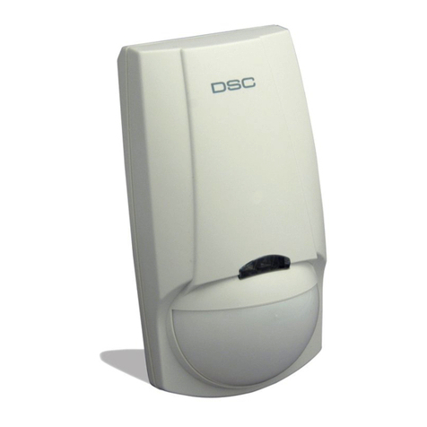
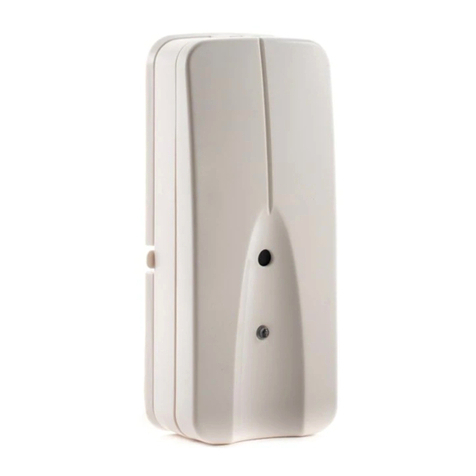
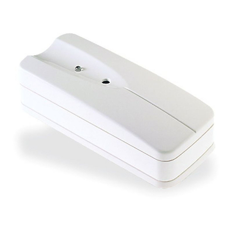
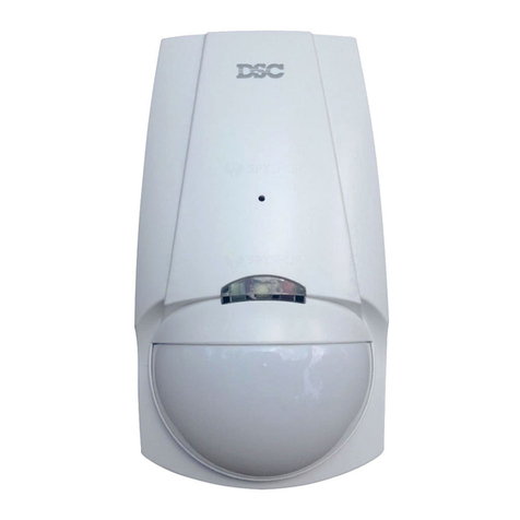
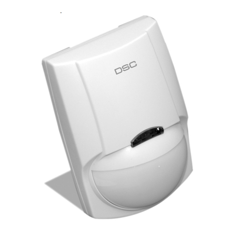
DSC LC-100-PI User manual

POLSKI

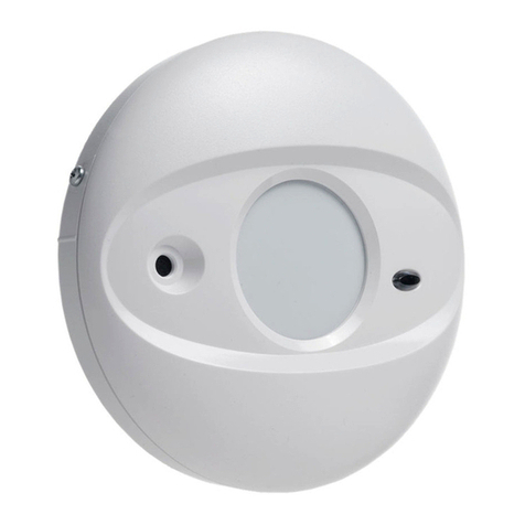
W czujce LC-100-PI / LC-120-PI wykorzystano specjalnie
zaprojektowaną soczewkę optyczną, oraz unikalny
czteroelementowy czujnik pasywnej podczerwieni (QUAD
PIR). Nową elektronikę czujki oparto na układzie ASIC,
który został specjalnie zoptymalizowany w celu
zapobiegania fałszywym alarmom wywoływanym przez
zwierzęta domowe.
Czujki LC-100-PI / LC-120-PI charakteryzują się wysoką
odpornością na światło widzialne. LC-100-PI / LC-120-PI
dostarczana jest wraz z soczewką szerokokątną.







WYBÓR MIEJSCA INSTALACJI





Aby uniknąć fałszywych alarmów, podczas montażu należy
stosować się do poniższych zasad:












MONTAŻ URZĄDZENIA
1. 


2. 

3. 



4. 

5. 

6. 



7. 

8. 
9. 





OPIS ZACISKÓW (Rys. 5)
Zaciski 1 i 2 (oznaczone „T1,T2”): 



Zacisk 3


Zacisk 4

Zacisk 5

Zaciski 6 i 7 (oznaczone „12V +/-„): 
 
ITALIANO

Il rivelatore LC-100-PI / LC-120-PI utilizza una speciale
lente, un esclusivo sensore piroelettrico Quad (quattro
elementi) ed una nuova elettronica basata su un’ASIC,
ottimizzati per eliminare i falsi allarmi provocati da animali
domestici. Offre un grado di immunità alla luce visibile
senza precedenti ed è dotato di una capacità di rivelazione
e di una stabilità veramente eccezionali in ogni tipo di
impianto di sicurezza. Il rivelatore LC-100-PI / LC-120-PI è
fornito con una lente volumetrica.
        
          
     


       


INSTALLAZIONE TYPICA
Scelta della posizione per il montaggio
         
          
         




Evitare le seguenti posizioni

           
      



        

     
  


FISSAGGIO
DEL RILEVATORE
1.         

2.  

3. 
         

4. 

5. 
6. 


7.     

8. 
9.      

       



INSTALLAZIONE DEL RIVELATORE
Descrizione della morsettiera 
Morsetti 1 & 2 - contrassegnati T2 e T1 (SABOTAGGIO). 




Morsetto 3 Marcato "NC"


Morsetto 4 Marcato "C"


Morsetto 5 Marcato "NO"     


Morsetto 6 - contrassegnato “–”(massa)
 


Morsetto 7 - contrassegnato “+”(+12V)













FRANCAIS

Le détecteur LC-100-PI / LC-120-PI utilise une lentille
optique spécialement conçue équipée d'un capteur IRP
Quad (quatre éléments) et de nouveaux composants
électroniques basés sur un ASIC pour éliminer les fausses
alarmes provoquées par les petites animaux et les
animaux domestiques. Le LC-100-PI / LC-120-PI offre des
niveaux inégalés d'immunité contre la lumière visible. Le
détecteur offre un niveau exceptionnel de stabilité et
capacité de détection pour toutes les installations de
sécurité. Le LC-100-PI / LC-120-PI est fourni avec une
lentille grand angle.      
       
       
       




INSTALLATION TYPIQUE
Sélectionnez l'emplacement de montage

          



  
Evitez les emplacements suivants
            
   



           
      
       


MONTAGE DU DETECTEUR
1. 

2. 
3. 


4. 

5. 
6.         
         

7. 
8. 
9.       


        


INSTALLATION DU DETECTEUR
Connexions de la plaque à bornes 
Bornes 1 & 2 - Signalées par T2 et T1 (TAMPER)  

 

       


Borne 3 marqué "NC"


Borne 4 marqué "C"
        

Borne 5 marqué "NO"


Borne 6 - Signalée par  -  (GND)     

Borne 7 - Signalée par

+

(+12 V) 
         






ESPANOL

El detector LC-100-PI / LC-120-PI utiliza una lente óptica
especialmente diseñada junto con un sensor PIR especial
Quad (de cuatro elementos) y un nuevo circuito integrado
de aplicación específica (ASIC) optimizado para eliminar
las falsas alarmas provocadas por pequeños animales y
mascotas. El LC-100-PI / LC-120-PI proporciona un grado
de inmunidad sin precedente contra la luz visible. El
detector aporta un grado de detección y de estabilidad
excepcional para cualquier instalación de seguridad. El
LC-100-PI / LC-120-PI está dotado de lentes de gran
angular.      
          
         


      

INSTALACIÓN TÍPICA
Seleccione la ubicación de montaje
         


          


Evite los siguientes emplazamientos:

  


        
     
   
        


MONTAJE DEL DETECTOR
 
        

         

  
   

        

 
         

        

 

 
         





INSTALACIÓN DEL DETECTOR

Terminales 1 y 2 - Marcados como "T2" y "T1" (TAMPER).
        

          


Terminal 3 marcado con "NC" 
        

Terminal 4 marcado con "C"    


Terminal 5 marcado con "NO"
        

Terminal 6 - Marcado como "-" (GND). 

Terminal 7 - Marcado como "+"(+12 V).   
          
        

ENGLISH
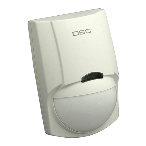
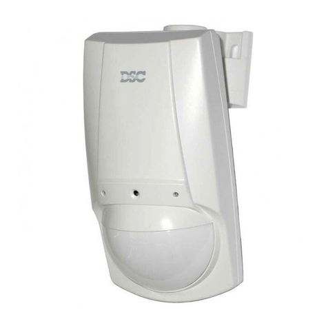
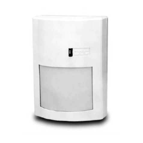
The LC-100-PI / LC-120-PI detector uses a special designed
optical Lens with unique Quad (Four element) PIR Sensor
and new ASIC based electronics optimized to eliminate
false alarms, caused by small animals and Pets. The LC-
100-PI / LC-120-PI provide unprecedented levels of
immunity against visible light. The Detector offers an
exceptional level of detection capability and stability for
every security installation. The LC-100-PI / LC-120-PI is
supplied with Wide Angle lens.
 



         


TYPICAL INSTALLATION
Select mounting location
         




Avoid the following locations
         








MOUNTING THE DETECTOR
1. 

2. 

3. 


4. 

5. 
6. 


7. 
8. 
9. 




DETECTOR INSTALLATION
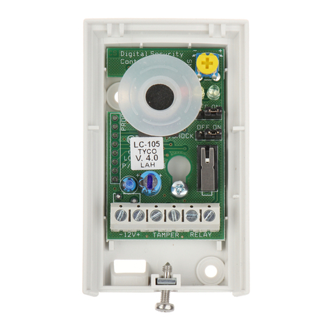
Terminal block connections 
Terminals 1 & 2 - Marked T2 and T1 (TAMPER)
        



Terminal 3 Marked "NC" - 


Terminal 4 Marked "C" 

Terminal 5 Marked "NO" -       


Terminal 6 - Marked  -  (GND)    

Terminal 7 - Marked  +  (+12V) 



LC-100-PI (Form A)
LC-120-PI (Form C)
Detector with Pet Immunity
Detector digital pasivo infrarrojo (PIR) con
inmunidad a mascotas
Détecteur numérique à infrarouge passif (IRP) avec
immunité aux animaux domestiques
Rivelatore digitale PIR con immunità agli animali
domestici
Cyfrowa czujka pasywnej podczerwieni (PIR)
odporna na obecność zwierząt

Fig 1III
I


Fig 2









Fig 3 I
II


USTAWIANIE CZUJKI
Zworka Licznika Impulsów



Pozycja 1







Pozycja 2







Pozycja 3









Zworka diody LED 

1.
 2.

Zworka funkcji odporności na zwierzęta








Regulacja zasięgu czujnika PIR ("SENS")






Wymagania dotyczące okablowania




Długość przewodu     
Średnica przewodu     
TEST INSTALACJI
UWAGA: 












SPECYFIKACJA TECHNICZNA
Metoda detekcji


Zasilanie 
Pobór prąduAktywność:)
Czuwanie:
Kompensacja
temperaturowa 
Czas trwania
alarmu 
Wyjście alarmowe






Przełącznik
sabotażowy




Czas nagrzewania 
Wskaźnik LED 

Odporność na
zakłócenia radiowe 

Odporność na
zakłócenia
statyczne 
Odporność na
zakłócenia
przepięciowe 
Temp. pracy 
Wymiary 
Waga 
IMPOSTAZIONE DEL RILEVATORE
Impostazione del Ponticello per il Conteggio Impulsi

Posizione 1





Posizione 2





Posizione 3






Impostazione del Ponticello di Abilitazione / Disabilitazione
del LED 
1. 2.
Impostazione del Ponticello per l’Immunitá agli Animali






Regolazione portata PIR (”SENS”)
 
         



Specifiche dei conduttori

        
        



     
     

     

     

PROVA DI COPERTURA
AVVERTENZA IMPORTANTE:
    
        
       

   

        

       

       
          

CARATTERISTICHE TECNICHE
Motodo di
rilevamento

Alimentazione 
AssorbimentoIn Funzione:
A Riposo:
Compensazione
Termica
Durata Allarme 
Uscita di Allarme




Deviatore
Antisabotaggio




Tempo di
Stabilizzazione 
Spia LED 
Immunità RFI        

Immunità alle
Scariche
Elettrostatiche 
Immunità agli
Impulsi 
Temperatura di
Funzionamento 
Dimensioni 
Peso 
CONFIGURATION DU DETECTEUR
Reglage Du Cavalier De Comptage D'impulsions



























Réglage Du Cavalier D'activation / Désactivation Des
Voyants

1. 
 2. 
Reglage Du Cavalier D'immunite Aux Animaux
Domestiques







Réglage de la portée du détecteur IRP (”SENS”)
        

        

Exigences en matière de dimensions des fils
 




     
     
     

     
TEST DE FONCTIONNEMENT
REMARQUE IMPORTANTE :  
       
     

       



       


        


CARACTERISTIQUES TECHNIQUES
Méthode de
détection
Alimentation en
entrée 
Appel de courantActif:

En veille:
Compensation de
temp. 
Durée d'alarme 
Sortie d'alarme





Interrupteur anti-
sabotage




Durée de
préchauffage 
Voyant indicateur     

Immunité contre
les fréquences
radio


Immunité statique 
Immunité
transitoire 
Temp. en
fonctionnement 
Dimensions 

Poids 
CONFIGURACIÓN DEL DETECTOR
Configuración Del Puente Del Contador De Impulsos























Configuración Del Puente De Activación / Desactivación
De Led 
1. 2.
Configuración Del Puente De Inmunidad Contra Mascotas








Ajuste del alcance del sensor PIR ("SENS")
        



Requisitos de tamaño de los cables
          
        
 


     
     
     
     
PRUEBA DE DESPLAZAMIENTO
NOTA IMPORTANTE:      
      


         
       
         

         
        


        

TECHNICAL SPECIFICATION
Método de detección

Alimentación 
Consumo de
corriente
Activo: 
Reposo:
Compensación
de temperatura 
Periodo de alarma 
Salida de la alarma




Interruptor de
seguridad




Periodo de
calentamiento 
Indicador LED     

Inmunidad a
radiofrecuencia        

Inmunidad a
electricidad estática



Transient Immunity 
Temperatura de
funcionamiento 
Dimensiones 

Peso 
SETTING-UP THE DETECTOR
Pulse Count Jumper Setting 
Position1:


Position2:





Position3:







Led Enable/Disable Jumper Setting 
1. 2.
Pet Immunity Jumper Setting 






PIR Range adjustment (”SENS”)
        

      


Wire size requirements
 



     
     
     
     

WALK TESTING
IMPORTANT NOTE:      
        













TECHNICAL SPECIFICATION
Detection Method 
Power Input 
CurrentDrawActive: ±
Standby:±
Temp
Compensation 
Alarm Period  ±0.5sec)
Alarm Outputs





Tamper Switch



Warm up Period 
±

LED Indicator 
RF Immunity       

Static Immunity 
Transient Immunity 
Operation Temp º º º º
Dimensions 

Weight 


Fig. 4III
I
Fig. 5III
I
Fig. 6
1













2


















3















4
 









5  



 



          
         

        



EN50131-1
EN50131-2-2 Grade 2 Class 2
P/N 7111670 Rev. E

This manual suits for next models

1

Other DSC Security Sensor manuals

DSC BV-400UL User manual

DSC

DSC BV-400UL User manual

DSC BRAVO5 User manual

DSC

DSC BRAVO5 User manual

DSC Encore PEC-300DP User manual

DSC

DSC Encore PEC-300DP User manual

DSC AMB-600 User manual

DSC

DSC AMB-600 User manual

DSC AMB-300 User manual

DSC

DSC AMB-300 User manual

DSC PG9905 User manual

DSC

DSC PG9905 User manual

DSC neo HSM2HOST User manual

DSC

DSC neo HSM2HOST User manual

DSC LC-100 PI User manual

DSC

DSC LC-100 PI User manual

DSC COMMUNIQUE VPM4580 User manual

DSC

DSC COMMUNIQUE VPM4580 User manual

DSC The NEW FORCE 2 F2-210 User manual

DSC

DSC The NEW FORCE 2 F2-210 User manual

DSC F2-220 User manual

DSC

DSC F2-220 User manual

DSC LC-100PI User manual

DSC

DSC LC-100PI User manual

DSC PG9934(P) User manual

DSC

DSC PG9934(P) User manual

DSC AC-500 User manual

DSC

DSC AC-500 User manual

DSC SG SECURITY MLR2-DV User manual

DSC

DSC SG SECURITY MLR2-DV User manual

DSC MAXSYS PC4400 User manual

DSC

DSC MAXSYS PC4400 User manual

DSC WLS904-418 User manual

DSC

DSC WLS904-418 User manual

DSC LC-104PIMW User manual

DSC

DSC LC-104PIMW User manual

DSC PC1150 User manual

DSC

DSC PC1150 User manual

DSC MAXSYS PC4020CF User guide

DSC

DSC MAXSYS PC4020CF User guide

DSC WS4955 User manual

DSC

DSC WS4955 User manual

DSC ws8904 User manual

DSC

DSC ws8904 User manual

DSC Acuity AMA-100 User manual

DSC

DSC Acuity AMA-100 User manual

DSC LC-103PIMSK User manual

DSC

DSC LC-103PIMSK User manual

Popular Security Sensor manuals by other brands

Johnson Controls tyco Bentel Security BW-IRC installation instructions

Johnson Controls

Johnson Controls tyco Bentel Security BW-IRC installation instructions

GJD D-TECT Dual Tech GJD360/AM installation guide

GJD

GJD D-TECT Dual Tech GJD360/AM installation guide

Tongdy PMD-18 Series manual

Tongdy

Tongdy PMD-18 Series manual

System Sensor WFD20 Installation and maintenance instructions

System Sensor

System Sensor WFD20 Installation and maintenance instructions

DSG HPGe Maintenance check sheet

DSG

DSG HPGe Maintenance check sheet

PCB Piezotronics M117B66 Installation and operating manual

PCB Piezotronics

PCB Piezotronics M117B66 Installation and operating manual

LEGRAND 0 490 8 installation instructions

LEGRAND

LEGRAND 0 490 8 installation instructions

AMC IF800T installation manual

AMC

AMC IF800T installation manual

B.E.G. LUXOMAT PD4N-DALILINK Mounting instructions

B.E.G. LUXOMAT

B.E.G. LUXOMAT PD4N-DALILINK Mounting instructions

Satel SILVER manual

Satel

Satel SILVER manual

Leedarson Multi-Sensor quick start guide

Leedarson

Leedarson Multi-Sensor quick start guide

Risco iWave RWX95 user manual

Risco

Risco iWave RWX95 user manual

SICK Prime KTX-WB94142252ZZZZ manual

SICK

SICK Prime KTX-WB94142252ZZZZ manual

MSA Chillgard VRF operating manual

MSA

MSA Chillgard VRF operating manual

Emerson Rosemount 2160 quick start guide

Emerson

Emerson Rosemount 2160 quick start guide

Honeywell Lyric quick start guide

Honeywell

Honeywell Lyric quick start guide

Bender EDS470-12 manual

Bender

Bender EDS470-12 manual

Panasonic HG-S Series user manual

Panasonic

Panasonic HG-S Series user manual

manuals.online logo
manuals.online logoBrands
  • About & Mission
  • Contact us
  • Privacy Policy
  • Terms and Conditions

Copyright 2025 Manuals.Online. All Rights Reserved.