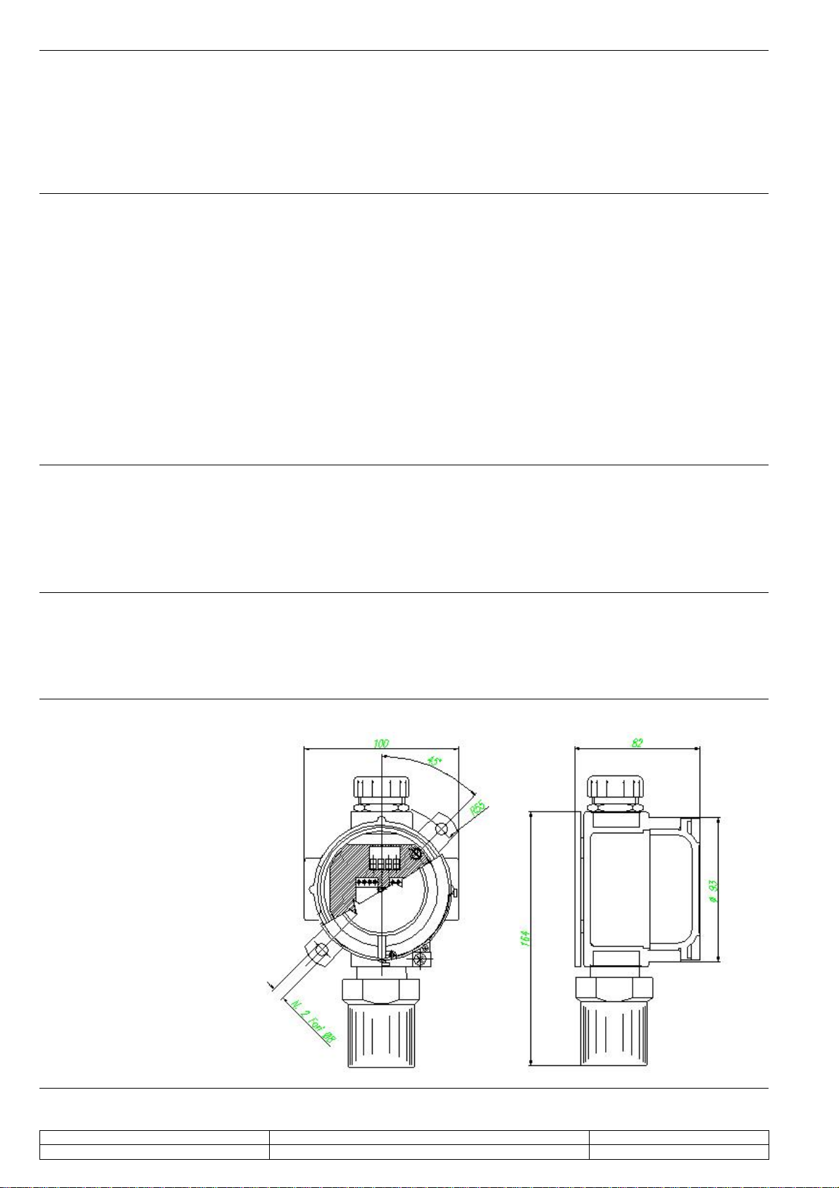
EsiWelma Srl URS20SI_en.doc - rev. 0 Oxygen detectors – URS20SI
20/10/2010 Gas detection systems for industrial environments 6/8
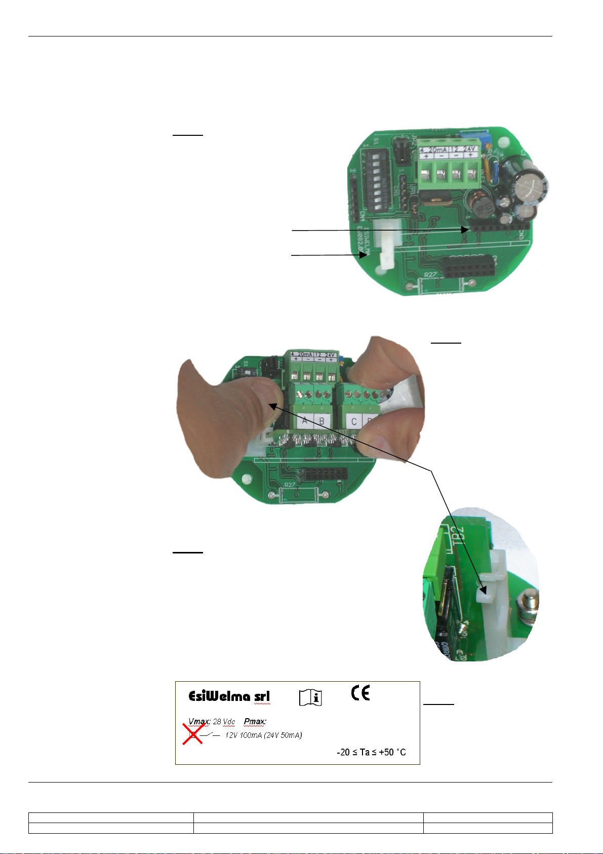
Electrical installation of
the optional relay card
Selecting the type of
contact on the terminal
board:
Configuring the relay
operating mode:
After mechanically installing the relay card, it is necessary to configure it electrically,
selecting the relay operating mode and the type of contact desired on the terminal
board (NC or NO).
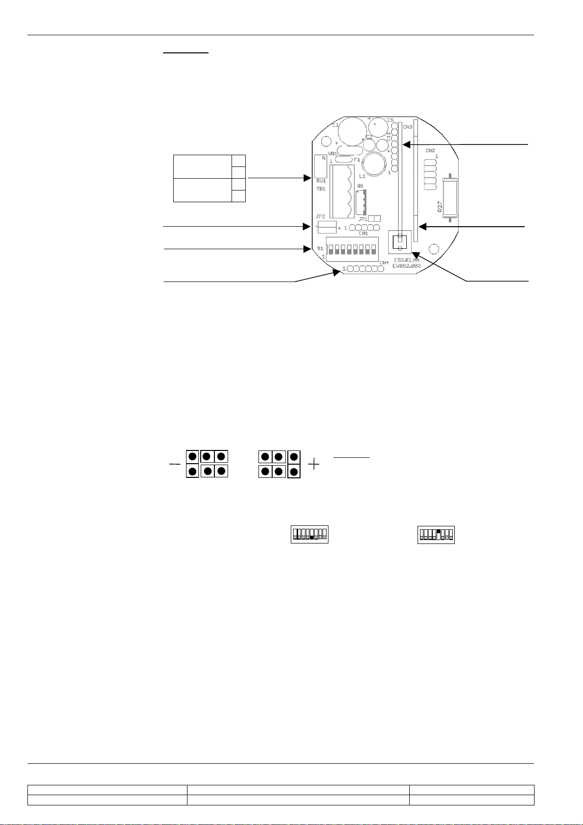
A pair of extractable terminals is available for each relay; the type of contact (NC or
NO) to be associated with them can be selected using the JP1…JP4 jumpers.
NC or NO contact of pre-alarm relay
NC or NO contact of 1st THRESHOLD relay
NC or NO contact of 2nd THRESHOLD relay
NC or NO contact of FAIL relay
DL1 (yellow), Sensor FAIL
DL2 (red), 2nd alarm THRESHOLD
DL3 (red), 1st alarm THRESHOLD
DL4 (red), Pre-alarm
Selecting the terminal contact:
NC NO
To set the operating mode of the relays: for direct (relay energised by event) or
reverse (relay energised with no event), it is necessary to use the 6th selector of the
DIP switch at S1; in particular:
direct operating mode reverse operating mode
Checklist after
mechanical and
electrical installation
The sensors are factory calibrated so they normally do not require any other
calibration once installed. Still, after installation, an operational check of the sensors
is recommended.
The detector will enter a 2-minute warm-up phase after power-up.
After this time, the sensor will switch to normal operating mode, but it will take about
2 hours before it reaches top performance level.
When the detector is operating, a gas response check should be carried out using
the TUL40.. gas calibration kit. This kit contains:
- 1 calibration gas cylinder: 4% of O2; (see kit part numbers on the specific
technical data sheet)
- pressure valve and flow regulator
- sensor body adapter
- about 2 metres of hose between cylinder and adapter.
During the test, check the output current, the status of the LED visible on the
outside of the enclosure and, if present, the status of the LEDs on the relay card
before closing the housing
The LED on the housing and the 4...20mA output have the following operating
meaning:
Sensor status 4...20mA Output Status LED on housing
WARM-UP 2mA Flashing at 2Hz frequency
OPERATING 1 flash about every 10 sec.
PRE-ALARM 2 flashes about every 5 sec.
1st ALARM THRESHOLD 3 flashes about every 5 sec.
2nd ALARM THRESHOLD
4...20mA
0,10,20mA for
threshold
applications
4 flashes about every 5 sec.
SENSOR FAIL 22mA Steady
D | B |
1 2 3 4 5 6 7 8
ON
1 2 3 4 5 6 7 8
ON