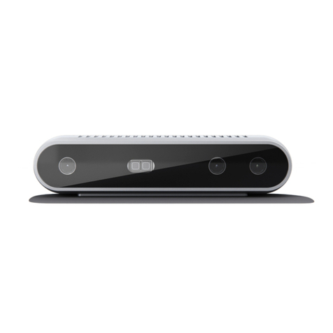
IFM O3R222 User manual

Operating instructions
2D/3D camera head
O3R222
O3R225
O3R252
11517817 / 0005 / 2023
GB

O3R222 O3R225 O3R252 2D/3D camera head
2
Contents
1 Preliminary note ............................................................. 3
1.1 Symbols used.......................................................... 3
1.2 Warnings.............................................................. 3
1.3 Legal and copyright information ............................................ 3
1.4 Open source information.................................................. 3
2 Safety instructions............................................................ 4
2.1 Safety symbols on the unit ................................................ 4
2.2 Laser safety ........................................................... 4
2.3 Cyber security.......................................................... 5
3 Intended use................................................................ 6
3.1 Application area ........................................................ 6
4 Installation.................................................................. 7
4.1 Heat management ...................................................... 8
5 Electrical connection.......................................................... 9
5.1 Wiring................................................................ 10
6 Scale drawings.............................................................. 11
6.1 O3R222 / O3R252 ...................................................... 11
6.2 O3R225 .............................................................. 12
7 Maintenance, repair and disposal................................................ 13
8 Approvals/standards.......................................................... 14
Glossary................................................................... 15

2D/3D camera head O3R222 O3R225 O3R252
3
1 Preliminary note
You will find instructions, technical data, approvals and further information using the QR code on the
unit / packaging or at documentation.ifm.com.
1.1 Symbols used
Requirement
Instructions
Reaction, result
[...] Designation of keys, buttons or indications
Cross-reference
Important note
Non-compliance may result in malfunction or interference.
Information
Supplementary note
1.2 Warnings
Warnings indicate the possibility of personal injury and damage to property. This enables safe product
handling. Warnings are graded as follows:
WARNING
Warning of serious personal injury
wIf the warning is not observed, fatal and serious injuries are possible.
CAUTION
Warning of minor to moderate personal injury
wIf the warning is not observed, minor to moderate injuries are possible.
ATTENTION
Warning of damage to property
wIf the warning is not observed, damage to property is possible.
1.3 Legal and copyright information
© All rights reserved by ifm electronic gmbh. No part of these instructions may be reproduced and
used without the consent of ifm electronic gmbh.
All product names, pictures, companies or other brands used on our pages are the property of the
respective rights owners.
1.4 Open source information
For more open source information see: documentation.ifm.com.

O3R222 O3R225 O3R252 2D/3D camera head
4
2 Safety instructions
• The unit described is a subcomponent for integration into a system.
– The system architect is responsible for the safety of the system.
– The system architect undertakes to perform a risk assessment and to create documentation in
accordance with legal and normative requirements to be provided to the operator and user of
the system. This documentation must contain all necessary information and safety instructions
for the operator, the user and, if applicable, for any service personnel authorised by the
architect of the system.
• Read this document before setting up the product and keep it during the entire service life.
• The product must be suitable for the corresponding applications and environmental conditions
without any restrictions.
• Only use the product for its intended purpose (Ò Intended use).
• If the operating instructions or the technical data are not adhered to, personal injury and/or damage
to property may occur.
• The manufacturer assumes no liability or warranty for any consequences caused by tampering with
the product or incorrect use by the operator.
• Installation, electrical connection, set-up, operation and maintenance of the product must be
carried out by qualified personnel authorised by the machine operator.
• Protect units and cables against damage.
2.1 Safety symbols on the unit
The following symbols are used on the device. Observe the subsequent sections in order to avoid
hazards:
Electric supply must correspond to IEC61010-1, chapter 9.4 - Limited-energy circuit.
Laser safety.
Device of protection class III. Only for operation in PELV circuits.
2.2 Laser safety
LASER
1
Marking on the device:
CLASS 1 LASER PRODUCT
IEC 60825-1:2014
21CFRPART1040
The device emits invisible laser radiation (λ=940 nm ±5 nm) of laser class 1 according to
• IEC 60825-1:2014 and
• EN 60825-1:2014.
USA
Complies with 21 CFR 1040.10 except for conformance with IEC60825-1 Ed.3, as described in Laser
Notice No.56, dated May 8,2019.

2D/3D camera head O3R222 O3R225 O3R252
5
Warning against opening the device or damaging it
WARNING
If the device has been opened or damaged, laser safety is no longer guaranteed.
wSkin or eye damage may occur.
uThe device may only be opened by the manufacturer.
uIf the device is damaged, stop using it and disconnect it from the power supply.
2.3 Cyber security
ATTENTION
Unprotected network environment.
The device does not include IT security measures according to IEC 62443.
wUnauthorised read or write access to data is possible.
wUnauthorised manipulation of the device function is possible.
uCheck and restrict access options to the device.

O3R222 O3R225 O3R252 2D/3D camera head
6
3 Intended use
The unit features a TOF (Time Of Flight) camera and, additionally, an RGB camera.
The TOF camera measures the distance between the camera and the object for each pixel by means
of the time-of-flight principle. For this purpose, the objects are illuminated with the internal infrared light
source.
The RGB camera uses ambient light to capture a colour image of the objects. The infrared light of the
TOF camera is not visible to the RGB camera.
The image processing system OVPxxx is additionally required to use the unit.
3.1 Application area
The device safety is rated for use under the following operating conditions according to EN IEC
61010-2-201:
• indoor use
• altitudes up to 4000 m
• relative air humidity up to max. 90%, non condensing
• pollution degree 2
Electromagnetic compatibility (EMC):
The unit is designed for use in industrial environments.
This product may cause radio interference in domestic areas.
uIf required, take appropriate EMC screening measures.
The IP rating has not been evaluated by UL® Underwriters Laboratories®.

2D/3D camera head O3R222 O3R225 O3R252
7
4 Installation
1
23 3
4 4
Fig.1: Installation of the device
1 Device 2 Field of view and illumination range of the device
3 Area to be kept free 4 Area without requirements
Installing the device:
uDo not place any objects in area (3).
wObjects in area (3) can cause measurement errors.
wObjects in area (4) are not a problem.
uAvoid transparent panes in the field of view and illumination range of the device (2).
wEven a very clean glass plate reflects some of the light. This means that measurement errors
are possible.
uInstall the device on heat-conductive metal parts or fixtures.
uAvoid installation in heavily polluted environments.
uConsider the installation tolerances when selecting an installation location.
Measurement errors when using the device
uFollow the instructions.
wIf the instructions are ignored, measurement errors are possible when using the device.
For cable lengths over 3 m between the device and the image processing system OVPxxx,
electrical insulation of the device is necessary.
uElectrically isolate the device from the earth.
wFor example, anodising or a coated mounting fixture can be used for insulation.

O3R222 O3R225 O3R252 2D/3D camera head
8
4.1 Heat management
ATTENTION
The device can heat up depending on the operating mode, the set parameters and the heat
dissipation to the environment.
The difference between the device’s surface temperature and the ambient temperature
must not exceed 25 degrees (according to IEC61010-2-201).
uReduce the surface temperature.
uAdjust the operating mode and the parameters.
The device develops a thermal power loss of up to 8 W, depending on the exposure time and frame
rate set (Ò Technical data).
uDesign a mounting fixture that can dissipate the thermal power loss.
wThe mounting fixture must meet the following properties:
- thermal connection with a thermal resistance < 2.5 K/W,
- cooling surface of > 10x10 cm,
- good heat-conducting material, for example aluminium.
uEnsure sufficient convection on the device and mounting fixtures.
wObstructions around the device and a high installation density may have a negative impact on
convection.
uReduce the exposure time or frame rate.
wThe surface temperature decreases if the parameters are reduced.

2D/3D camera head O3R222 O3R225 O3R252
9
5 Electrical connection
The device must be connected by a qualified electrician.
uDisconnect power before connecting the device.
uUse strain reliefs for cables connected to the device.
Protection class III device (IEC 61010-2-201 chap. 6.5.2.101.4).
The electrical supply must
• be provided only by PELV circuits (IEC 61010-2-201 chap. 3.111),
• not exceed 35 V DC during operation,
• not exceed 60 V DC in the event of a single fault and
• not exceed the permitted operating voltage of the device (see data sheet).
The separation of external circuits must comply with IEC61010-2-201, Figure 102.
WARNING
Unsuitable power supply
wElectric shock may cause serious injury or death.
uUse a PELV power supply within the specified voltage range.
Use energy-limited circuits for the electrical supply (IEC 61010-1 chap. 9.4). The energy of the circuit
can be limited at an operating voltage of 24 V by an overcurrent protection device. The overcurrent
protection device must switch off a current of 8.3A in maximum 120s. Observe the specific tripping
characteristic. Possible overcurrent protection devices:
• fuse or
• non-adjustable and non-self-reclosing electromechanical device.
Separate the circuit from other, non-energy-limited circuits by at least basic insulation.
ATTENTION
No suitable energy limitation of the circuit
wFire hazard in case of a malfunction.
uUse energy-limited circuit according to IEC 61010-1 chap. 9.4.
ATTENTION
Devices damaged due to overload
wA camera head has 2 connections. If both connections are connected to different image
processing systems at the same time, an overload will occur. This will damage the
devices.
uConnect a camera head to only one image processing system.
High signal damping due to long coaxial cables
uUse a maximum cable length of 20 m for the coaxial lines to the sensor ports.
When the camera head is connected to an image processing system:
uObserve the operating instructions of the image processing system.

O3R222 O3R225 O3R252 2D/3D camera head
10
5.1 Wiring
1 2
Fig.2: Wiring
1 TOF camera (coaxial connection) 2 RGB camera (coaxial connection)

2D/3D camera head O3R222 O3R225 O3R252
11
6 Scale drawings
6.1 O3R222 / O3R252
45
90
29
123
18,7 7,715
15,4
31
1
2
8
°
6
0
°
6
0
°
26
4
5
°
4
5
°
8
0
°
41,741,7
12,2
M3
Fig.3: Scale drawing
1 RGB camera 2 TOF camera
3 Illumination unit

O3R222 O3R225 O3R252 2D/3D camera head
12
6.2 O3R225
45
90
29
123
18,7 7,715
15,4
31
1
1
0
°
1
2
8
°
1
0
5
°
26
9
0
°
7
8
°
8
0
°
41,741,7
12,2
M3
Fig.4: Scale drawing
1 RGB camera 2 TOF camera
3 Illumination unit

2D/3D camera head O3R222 O3R225 O3R252
13
7 Maintenance, repair and disposal
Soiling reduces the contrast and the recognition performance.
uKeep the front pane free from soiling.
uDo not open the device.
wThe device does not contain any components which can be maintained by the user. The device
must only be repaired by the manufacturer.
uUse glass cleaner for cleaning.
Cleaning agents containing solvents and silicone may damage the device.
uOnly use cleaning agents without solvents and silicone.
uIn environments with a high pollution degree, clean the device regularly.
uAfter use, dispose of the unit in an environmentally friendly way in accordance with the applicable
national regulations.

O3R222 O3R225 O3R252 2D/3D camera head
14
8 Approvals/standards
For approvals and standards, the following information is available:
• Test standards and regulations: documentation.ifm.com
• EU declaration of conformity and approvals: documentation.ifm.com
• Notes relevant for approval: package inserts of the device

2D/3D camera head O3R222 O3R225 O3R252
15
Glossary
Convection
Convection is the air movement around the
unit. Sufficient air movement is necessary
to prevent the unit from overheating.
This manual suits for next models
2
Table of contents
Other IFM 3D Camera manuals