GeoCue True View 515 Installation manual

True View 515 Hardware User Guide
10/26/2021
GeoCue Group, Inc
10/26/2021
Version 1.0.2
Updated for Firmware Version 3.0.7.1

True View 515 Hardware User Guide
2 True View 515 Hardware User Guide 10/26/2021
Contents
About GeoCue Group, Inc. ......................................................................................................................4
About True View® 515............................................................................................................................. 5
A True View Cycle ................................................................................................................................... 5
True View Hardware Integration Kit (M600)............................................................................................6
Installing the Top Plate and Controller Box .........................................................................................6
Installing the Ronin Mount ................................................................................................................ 10
True View Hardware Integration Kit (M300) ............................................................................... 12
Installing the Controller Plate, Antenna Mast Base .............................................................. 12
Installing M300 True View Mounting Bracket.................................................................................... 14
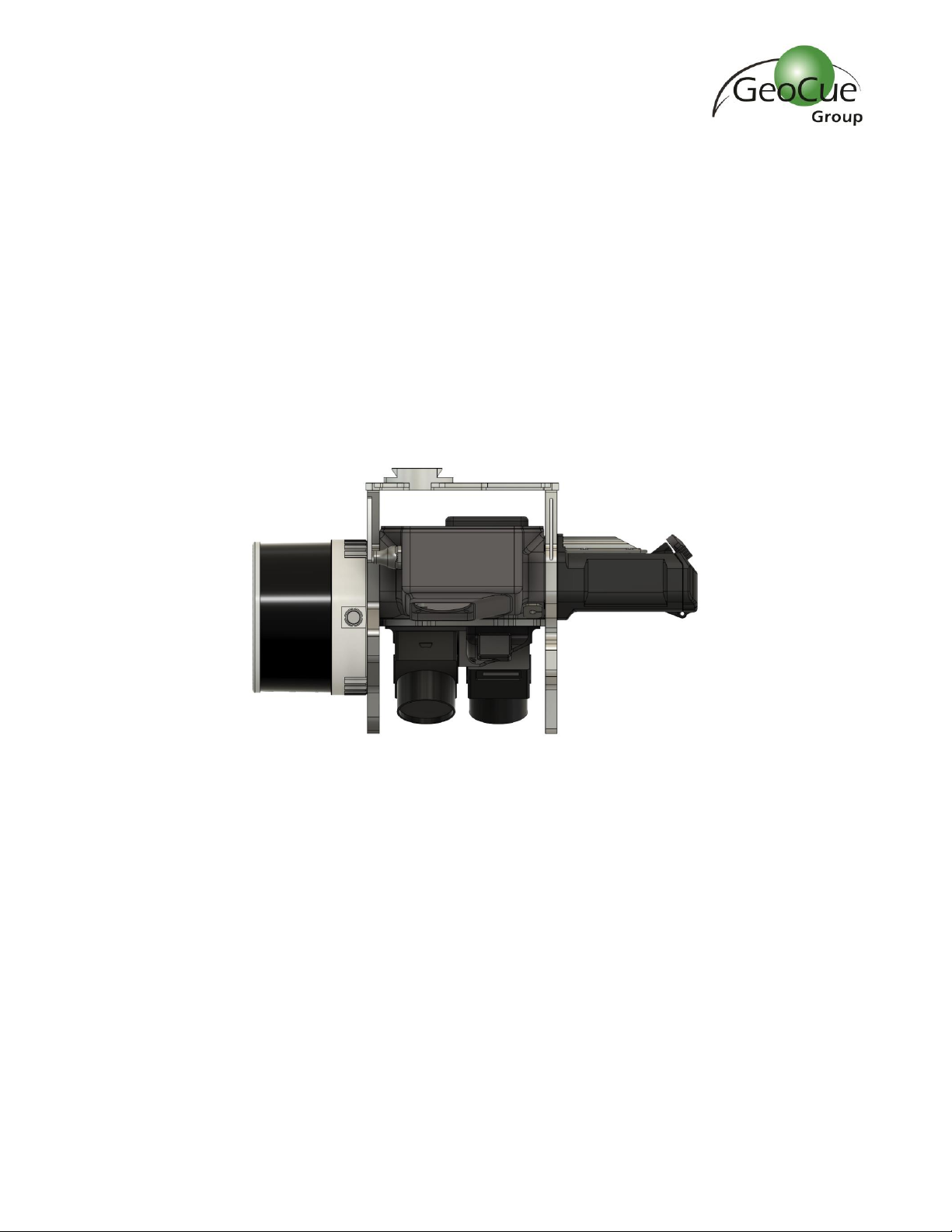
True View 3DIS Installation ....................................................................................................................17
True View Battery ................................................................................................................................. 21
True View Data Storage Devices...........................................................................................................22
UMS..................................................................................................................................................22
Camera SD Cards ..............................................................................................................................22
System Configuration File (SCF)........................................................................................................22
Core Configuration File (CCF)............................................................................................................ 23
CCFSection6 –POS ....................................................................................................................... 23
CCFSection8 –Camera..................................................................................................................24
CCFSection11 –Configuration Laser.............................................................................................. 25
CCFSection15 –Battery.................................................................................................................26
CCFSection16 - Cycle .................................................................................................................... 27
CCFSection17 –Storage Auto Delete ............................................................................................ 28
True View 515 Field Operations.............................................................................................................28
1. Base Station ..............................................................................................................................28
2. Pre-Flight ..................................................................................................................................29
3. Disable Obstacle Avoidance ...................................................................................................... 30
4. Center of Gravity (GC) Calibration ............................................................................................. 31
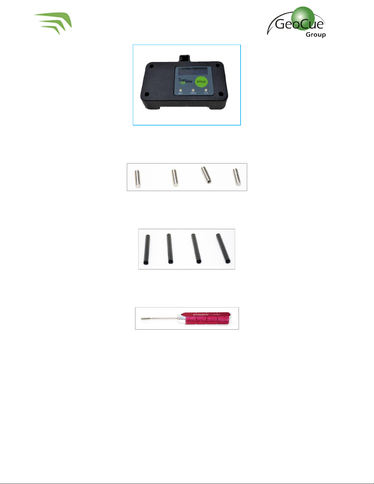
5. Controller Box LEDs .................................................................................................................. 32
6. Heading Alignment Maneuver................................................................................................... 35
7. After Landing ............................................................................................................................ 36

True View 515 Hardware User Guide
3 True View 515 Hardware User Guide 10/26/2021
True View EVO...................................................................................................................................... 37
Logging in To APX15............................................................................................................................. 37
Configure True View Wi-fi ................................................................................................................. 37
Log in to APX-15 ............................................................................................................................... 39
Download T04 Files....................................................................................................................... 39
Measuring GNSS Lever Arm Offsets ..................................................................................................... 40
Z Offset............................................................................................................................................. 41
X Offset............................................................................................................................................. 42
Y Offset............................................................................................................................................. 43
True View 3DIS/M600 Pro –Mission Checklist.......................................................................................44
Hardware Maintenance.........................................................................................................................46
Dust Filter .........................................................................................................................................46
FAQ ......................................................................................................................................................48
Support.................................................................................................................................................49

True View 515 Hardware User Guide
4 True View 515 Hardware User Guide 10/26/2021
About GeoCue Group, Inc.
GeoCue Group was founded in 2003 by a group of engineers with extensive experience in developing
hardware and software solutions for primary remote-sensed data acquisition. Our initial products were
aimed at reducing schedule and cost risk in geospatial production workflows by providing
organizational, productivity and data management tools for base geospatial data production. These
tools have been realized as the GeoCue product family. Today GeoCue workflow management tools are
used by a majority of North American geospatial production shops. In 2005, GeoCue began selling and
supporting Terrasolid tools for kinematic LIDAR data production. This was followed in 2009 by our
acquisition of QCoherent Software LLC, the creator of the point cloud exploitation toolset, LP360.
Today GeoCue is the largest supplier of kinematic LIDAR processing tools in North America and LP360
is the world’s most widely used tool for exploiting point cloud data. In 2014, GeoCue Group started a
division focused on using small Unmanned Aerial Systems for high accuracy mapping. Leveraging our
expertise in production, risk reduction, and point cloud processing tools, we are continuing to bring new
services and products to market to provide surveyors and other geomatics professionals exciting tools
for geospatial data extraction using low cost drones including Loki, our plug-and-play PPK direct
positioning system, and now our new True View LIDAR/Imagery fusion sensors. To learn more, visit
www.geocue.com.

True View 515 Hardware User Guide
5 True View 515 Hardware User Guide 10/26/2021
About True View® 515
The True View® 515 is GeoCue’s latest addition to our LIDAR/camera fusion platform designed from the
ground up to generate high accuracy 3D colorized LIDAR point clouds. Featuring dual GeoCue Mapping
Cameras, Hesai PandarXT-32 laser scanner and Applanix Position and Orientation System (POS), the
result is a true 3D imaging sensor (3DIS). With its wide 120° fused field of view, the True View 515
provides high efficiency 3D color mapping and will redefine LIDAR wire extraction and dense vegetation
penetration applications for all- purpose grade sensors.
A True View Cycle
All True View sensors write their various data streams to a standard file folder structure called a “Cycle.”
The original meaning of cycle was an on/off cycle of the sensor. It is possible to have multiple collections
(flights, in the case of a drone) in a single Cycle, so it is not necessarily correct to think of cycle as being
synonymous with a flight.

True View 515 Hardware User Guide
6 True View 515 Hardware User Guide 10/26/2021
True View Hardware Integration Kit (M600)
The True View 3DIS was designed to be used with the GeoCue True View Integration kit, which includes
an antenna mounting plate and a DJI Ronin gimbal mount with vibration dampeners. If your True View
3DIS and M600 were purchased through GeoCue, the antenna mounting plate and Ronin mount were
installed by a GeoCue technician. If you purchased your M600 from a third party, you will need to install
these components before using your True View system. The following steps explain how to install your
True View integration kit.
Installing the Top Plate and Controller Box
1. To install the top plate and controller box you will need the following components:
a. Top plate with antenna mast. (Figure 1)
Figure 1 –Top Plate with Antenna Mast
b. Controller box without LED Readout (Figure 2) or with LED readout (Figure 3)
Figure 2 –Controller box without readout display

True View 515 Hardware User Guide
7 True View 515 Hardware User Guide 10/26/2021
Figure 3 - Controller Box with readout display
c. Set Screw (4) (Figure 4)
Figure 4 –Set Screws
d. 50mm Spacer (4) (Figure 5)
Figure 5 - Spacers
e. Hex Driver –1.5mm & 2mm (Figure 6)
Figure 6 –Hex Driver
2. On the drone, remove the 4 screws indicated below (Figure 7). These screws will be used to
attach the mounting plate later, so save them for step 5.

True View 515 Hardware User Guide
8 True View 515 Hardware User Guide 10/26/2021
Figure 7 –Prepare for mounting
3. Apply Loctite to the 4 Set Screws and install in the empty screw spaces from Step 2 using a
1.5mm hex driver (Figure 8). WARNING - Do not overtighten. If screws are too tight, they will
press into the plastic plate below and could cause the plate to crack.
Figure 8 –Install set screws
4. Install the four 50mm spacers on top of the set screws (Figure 9).

True View 515 Hardware User Guide
9 True View 515 Hardware User Guide 10/26/2021
Figure 9 –Install spacers
5. Line the plate up on top of the spacers. Apply Loctite to the 4 screws removed in Step 2 (Figure
10) and secure the plate to the top of the spacers (Figure 11).
Figure 10 –Loctite the removed screws
Figure 11 –Install the controller box
6. Install the controller box on to the top plate with the LEDs facing out away from the center of
the drone. The controller box is designed to fit into the antenna mounting plate without the
need for additional hardware.

True View 515 Hardware User Guide
10 True View 515 Hardware User Guide 10/26/2021
Installing the Ronin Mount
1. On the drone, remove the 3 screws on each leg of the stock mount (Figure 12). Keep the
screws, they will be used again.
Figure 12 –Remove stock mount screws
2. On the Ronin Mount, loosen the screws that hold the legs to the rails enough so that they can
be rotated (Figure 13).
Figure 13 –Loosen leg screws
3. Rotate legs so that the mount stands off the drone (Figure 14).

True View 515 Hardware User Guide
12 True View 515 Hardware User Guide 10/26/2021
True View Hardware Integration Kit (M300)
The True View 3DIS was designed to be used with the GeoCue True View Integration kit, which includes
an antenna mast base and a True View mounting bracket for M300 with vibration dampeners. If your
True View 3DIS and M300 were purchased through GeoCue, the antenna mast base and True View
mounting bracket were installed by a GeoCue technician. If you purchased your M300 from a third
party, you will need to install these components before using your True View system. The following
steps explain how to install your True View integration kit.
Installing the Controller Plate, Antenna Mast Base
1. To install the controller plate and antenna mast base you will need the components listed
below.
a. (1) Antenna Mast Base (Figure 16)
Figure 16 –Antenna Mast Base
b. (1) Controller Plate (Figure 17)
Figure 17 –Controller Plate
c. Torque screwdriver set to 5.7 Inch-Pounds (INLB) (Figure 18)
Figure 18

True View 515 Hardware User Guide
13 True View 515 Hardware User Guide 10/26/2021
d. Threadlocker –Removeable Blue 242.
e. (2) M3 x 0.5 - 8mm length screw
f. (2) M3 x 0.5 - 10mm length screw
g. (2) 4mm Spacer
Apply Threadlocker to all screws and tighten to 5.7 inch pounds. Figure 19 shows the installation
diagram.
Figure 19

True View 515 Hardware User Guide
14 True View 515 Hardware User Guide 10/26/2021
Installing M300 True View Mounting Bracket
i. M300 True View mounting bracket (Figure 20) with slanted TPU spacer (Figure 22)
attached.
Figure 20 –M300 True View bracket
j. (2) M3 x 0.5 - 10mm length screw
k. (2) M3 Nylon Washer
l. (2) M3 x 0.5 –20mm length screw
m. (2) Slanted TPU Spacer

True View 515 Hardware User Guide
15 True View 515 Hardware User Guide 10/26/2021
1. Invert the drone so the bottom is facing up.
2. Apply threadlocker to the M3 x 0.5 –10mm length screws and install on the front two hole of
the bracket and aircraft body. The M3 nylon washers go between the M300 body and the True
View bracket (Figure 21). Tighten screws with torque wrench using 5.7 inch-pounds of torque.
Figure 21
3. Place TPU spacers between the bottom of the aircraft and the True View bracket. The angle of
the spacers match the aircraft body (Figure 22).

True View 515 Hardware User Guide
17 True View 515 Hardware User Guide 10/26/2021
True View 3DIS Installation
The True View 3DIS mounts using a standard DJI Ronin mount on the DJI M600. The instructions below
describe how to install the True View 410 on the M600 when you are ready to use the system to collect
data.
1. Place the drone on a stable surface with the landing gear down.
2. Turn the red lever (Figure 23) on the Ronin mount until it is loose, but do not remove it
completely.
Figure 23 –Ronin mount locking lever
3. Align True View so that the battery compartment is facing forward on the drone and the laser
scanner is towards the back.
4. From the back of the drone, lift the True View up to the mount from the left side and slide the
True View mount into the Ronin mount (Figure 24). Slide until the True View dove tail is in the
center of the Ronin mount (Figure 25).
Figure 24 –Ronin mount

True View 515 Hardware User Guide
18 True View 515 Hardware User Guide 10/26/2021
Figure 25 –True View 410 in Ronin mount
5. Tighten the red lever until the True View is tightly locked in place.
6. Loop the safety lanyard through the upper metal plate of the True View and around one of the
bars of the payload mount and close the safety lanyard (Figure 26).
Figure 26 –Safety lanyard
7. Connect the USB or CAT6 cable to the controller box (Figure 27) and route it down to the True
View unit. Be sure to secure any excess cable but leave enough slack to prevent tension on the
connector. The cable type depends on your controller firmware.

True View 515 Hardware User Guide
19 True View 515 Hardware User Guide 10/26/2021
Figure 27 –Control box cable
8. Attach the USB or CAT6 cable to the True View unit (Figure 28). Be sure to secure any excess
cable but leave enough slack to prevent tension on the connector.
Figure 28 –Control box cable into True View
9. Attach the GNSS antenna cable to the True View unit (Figure 28) and screw the antenna onto
the antenna mount (Figure 29) or insert into the revision 2 antenna mount. Do not use the
integral mount on the readout controller box if your control box has one as this feature has
been deprecated. Be sure to secure any excess cable but leave enough slack to prevent tension
on the connector.

True View 515 Hardware User Guide
20 True View 515 Hardware User Guide 10/26/2021
Figure 29 –GNSS antenna
Table of contents
Other GeoCue 3D Camera manuals